STREETS/INLETS/STORM SEWERS
CONTENTS
Section Page
ST-
1.0 INTRODUCTION ... 1
1.1 Purpose... 1
1.2 Urban Stormwater Collection and Conveyance Systems... 1
1.3 Components of Urban Stormwater Collection and Conveyance Systems ... 2
1.4 Minor and Major Storms ... 3
2.0 STREET DRAINAGE... 4
2.1 Street Function and Classification ... 4
2.2 Design Considerations... 5
2.3 Hydraulic Evaluation ... 7
2.3.1 Curb and Gutter ... 7
2.3.1.1 Gutters With Uniform Cross Slopes (i.e., Where Gutter Cross Slope = Street Cross Slope) ... 7
2.3.1.2 Gutters With Composite Cross Slopes (i.e., Where Gutter Cross Slope ≠ Street Cross Slope)... 8
2.3.1.3 Allowable Gutter Hydraulic Capacity ... 9
2.4 Major Storm Hydraulics ... 11
2.4.1 Purpose and Objectives... 11
2.4.2 Street Hydraulic Capacity ... 11
3.0 INLETS ... 16
3.1 Inlet Functions, Types and Appropriate Applications ... 16
3.2 Design Considerations... 16
3.3 Hydraulic Evaluation ... 18
3.3.1 Grate Inlets (On a Continuous Grade)... 18
3.3.2 Curb-Opening Inlets (On a Continuous Grade)... 20
3.3.3 Combination Inlets (On a Continuous Grade) ... 21
3.3.4 Slotted Inlets (On a Continuous Grade) ... 22
3.3.5 Inlets Located in Sumps ... 22
3.3.6 Inlet Clogging... 24
3.4 Inlet Location and Spacing on Continuous Grades ... 27
3.4.1 Introduction ... 27
3.4.2 Design Considerations... 27
3.4.3 Design Procedure ... 27
4.0 STORM SEWERS ... 31
4.1 Introduction ... 31
4.2 Design Process, Considerations, and Constraints ... 31
4.3 Storm Sewer Hydrology... 33
4.3.1 Peak Runoff Prediction ... 33
4.4 Storm Sewer Hydraulics (Gravity Flow in Circular Conduits) ... 34
4.4.1 Flow Equations and Storm Sewer Sizing ... 34
4.4.2 Energy Grade Line and Head Losses ... 35
4.4.2.1 Losses at the Downstream Manhole—Section 1 to Section 2 ... 36
4.4.2.2 Losses in the Pipe, Section 2 to Section 3. ... 37
4.4.2.3 Losses at the Upstream Manhole, Section 3 to Section 4... 38
4.4.2.4 Juncture and Bend Losses at the Upstream Manhole, Section 4 to Section 1... 38
4.4.2.5 Transitions ... 40
4.4.2.6 Curved Sewers ... 41
4.4.2.7 Losses at Storm Sewer Exit ... 41
5.0 SPREADSHEETS... 45
6.0 EXAMPLES... 46
6.1 Example—Triangular Gutter Capacity... 46
6.2 Example—Composite Gutter Capacity... 48
6.3 Example—Composite Gutter Spread ... 50
6.4 Example—V-Shaped Swale Capacity ... 52
6.5 Example—V-Shaped Swale Design ... 52
6.6 Example—Major Storm Street Capacity... 52
6.7 Example—Grate Inlet Capacity ... 53
6.8 Example—Curb-Opening Inlet Capacity... 54
6.9 Example—Curb-Opening Inlet Capacity... 57
6.10 Example—Combination Inlet Capacity ... 59
6.11 Example—Curb-Opening Inlet in a Sump Condition ... 62
6.12 Example—Storm Sewer Hydraulics (Akan and Houghtalen 2002) ... 62
6.13 Example—Storm Sewer Hydrology ... 64
7.0 REFERENCES ... 78
Tables Table ST-1—Street Classification for Drainage Purposes ... 4
Table ST-2—Pavement Encroachment Standards for the Minor Storm ... 5
Table ST-3—Street Inundation Standards for the Major (i.e., 100-Year) Storm ... 6
Table ST-4—Allowable Cross-Street Flow ... 6
Table ST-5—Applicable Settings for Various Inlet Types... 16
Table ST-6—Splash Velocity Constants for Various Types of Inlet Grates ... 19
Table ST-7—Sag Inlet Discharge Variables and Coefficients... 24
Table ST-8—Clogging Coefficients to Convert Clogging Factor From Single to Multiple Units1... 26
Table ST-9—Bend Loss and Lateral Loss Coefficients (FHWA 1996)... 40
Table ST-10—Head Loss Expansion Coefficients in Non-Pressure Flow (FHWA 1996) ... 41
Table ST-11—Hydrologic Parameters at Manholes ... 66
Table ST-12—Vertical Profile Information of Sewers ... 66
Figures Figure ST-1a—Typical Gutter Sections—Constant Cross Slope ... 13
Figure ST-1b—Typical Gutter Sections—Composite Cross Slope ... 13
Figure ST-2—Reduction Factor for Gutter Flow... 14
Figure ST-3—Typical Street-Side Swale Sections—V-Shaped ... 15
Figure ST-4—Perspective Views of Grate and Curb-Opening Inlets ... 29
Figure ST-5—Curb-Opening Inlets ... 30
Figure ST-6—A Manhole-Sewer Unit ... 42
Figure ST-8—Bend Loss Coefficients ... 43
Figure ST-9—Access Hole Benching Methods ... 44
Figure ST-10—Angle of Cone for Pipe Diameter Changes... 44
Photographs Photograph ST-1—The critical role that streets play in urban inlet and storm sewer drainage is often not properly taken into account... 2
Photograph ST-2—The capital costs of storm sewer construction are large, emphasizing the importance of sound design. ... 2
Photograph ST-3—Gutter/street slope is a major design factor for both street and inlet capacity. ... 20
Photograph ST-4—Inlets that are located in street sags and sumped can be highly efficient. ... 22
Photograph ST-5—Clogging is an important consideration when designing inlets... 25
1.0 INTRODUCTION 1.1 Purpose
The purpose of this chapter is to give concise, practical guidelines for the design of urban stormwater collection and conveyance systems. Procedures and equations are presented for the hydraulic design of street drainage, locating inlets and determining capture capacity, and sizing storm sewers. In addition, examples are provided to illustrate the hydraulic design process. Spreadsheet solutions accompany the hand calculations for most example problems.
The design procedures presented in this chapter are based upon fundamental hydrologic and hydraulic design concepts. The design equations provided are well accepted and widely used. They are presented without derivations or detailed explanation, but are properly referenced if the reader wishes to study their background. Therefore, it is assumed that the reader has a fundamental understanding of basic
hydrology and hydraulics. A working knowledge of the Rational equation (RUNOFF chapter) and open channel hydraulics (MAJOR DRAINAGE chapter) is particularly helpful.
1.2 Urban Stormwater Collection and Conveyance Systems
Urban stormwater collection and conveyance systems are critical components of the urban infrastructure. Proper design of these systems is essential to minimize flood damage and disruptions in urban areas during storm events while protecting the urban water resources environment. Their primary function is to collect excess stormwater from street gutters, convey the excess stormwater through storm sewers and along the street right-of-way, and discharge it into a detention basin, water quality best management practice (BMP) or the nearest receiving water body (FHWA 1996).
Urban stormwater collection and conveyance systems must fulfill many objectives. Properly functioning urban drainage systems:
• Minimize disruption to the natural drainage system.
• Promote safe passage of vehicular traffic during minor storm events.
• Maintain public safety and manage flooding during major storm events.
• Preserve and protect the urban stream environment.
• Minimize capital and maintenance costs of the system.
All of these objectives are important, but the public is the most vocal about disruptions to traffic and street flooding when storm drainage systems are not designed properly.
Photograph ST-1—The critical role that streets play in urban inlet and storm sewer drainage is often not properly taken into account.
Photograph ST-2—The capital costs of storm sewer construction are large, emphasizing the importance of sound design.
1.3 Components of Urban Stormwater Collection and Conveyance Systems
components: (1) street gutters and roadside swales, (2) stormwater inlets, and (3) storm sewers (and appurtenances like manholes, junctions, etc.). Street gutters and roadside swales collect runoff from the street (and adjacent areas) and convey the runoff to a stormwater inlet while maintaining the street’s level-of-service.
Inlets collect stormwater from streets and other land surfaces, transition the flow into storm sewers, and often provide maintenance access to the storm sewer system. Storm sewers convey stormwater in excess of a street’s or a swale’s capacity along the right-of-way and discharge it into a stormwater management facility or a nearby receiving water body. In rare instances, stormwater pump stations (the design of which is not covered in this Manual) are needed to lift and convey stormwater away from
low-lying areas where gravity drainage is not possible. All of these components must be designed properly to achieve the stormwater collection and conveyance system’s objectives.
1.4 Minor and Major Storms
Rainfall events vary greatly in magnitude and frequency of occurrence. Major storms produce large flow rates but rarely occur. Minor storms produce smaller flow rates but occur more frequently. For economic reasons, stormwater collection and conveyance systems are not normally designed to pass the peak discharge during major storm events.
Stormwater collection and conveyance systems are designed to pass the peak discharge of the minor storm event (and smaller events) with minimal disruption to street traffic. To accomplish this, the spread of water on the street is limited to some maximum, mandated value during the minor storm event. Inlets must be strategically placed to pick up the excess gutter or swale flow once the limiting spread of water is reached. The inlets direct the water into storm sewers, which are typically sized to pass the peak flow rate from the minor storm without any surcharge. The magnitude of the minor storm is established by local ordinances or criteria, and the 2-, 5-, or 10-year storms are most commonly specified.
On occasion, storms will occur that surpass the magnitude of the minor storm event. When this happens, the spread of water on the street exceeds the allowable spread and the capacity of the storm sewers designed for the minor storm event. Street flooding occurs and traffic is disrupted. However, proper design requires that public safety be maintained and the flooding be managed to minimize flood damage. Thus, local ordinances also often establish the return period for the major storm event, generally the 100-year storm. For this event, the street becomes an open channel and must be analyzed to determine that the consequences of the flood are acceptable with respect to flood damage and public safety.
2.0 STREET DRAINAGE 2.1 Street Function and Classification
The primary function of a street or roadway is to provide for the safe passage of vehicular traffic at a specified level of service. If stormwater collection and conveyance systems are not designed properly, this primary function can be impaired. To make sure this does not happen, streets are classified for drainage purposes based on their traffic volume, parking practices, and other criteria (Wright-McLaughlin Engineers 1969). The four street classifications are:
• Local (low-speed traffic for residential or industrial area access).
• Collector (low/moderate-speed traffic providing service between local streets and arterials).
• Arterial (moderate/high-speed traffic moving through urban areas and accessing freeways).
• Freeway (high-speed travel, generally over long distances).
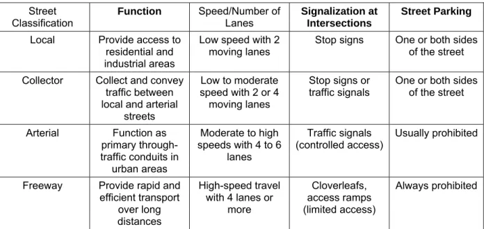
Table ST-1 provides additional information on the classification of streets for drainage purposes.
Table ST-1—Street Classification for Drainage Purposes
Street
Classification Function Speed/Number of Lanes Signalization at Intersections
Street Parking
Local Provide access to residential and industrial areas
Low speed with 2 moving lanes
Stop signs One or both sides of the street Collector Collect and convey
traffic between local and arterial
streets
Low to moderate speed with 2 or 4
moving lanes
Stop signs or
traffic signals One or both sides of the street
Arterial Function as primary through-traffic conduits in
urban areas
Moderate to high speeds with 4 to 6
lanes
Traffic signals
(controlled access) Usually prohibited
Freeway Provide rapid and efficient transport
over long distances
High-speed travel with 4 lanes or
more
Cloverleafs, access ramps (limited access)
Always prohibited
Streets serve another important function other than traffic flow. They contain the first component in the urban stormwater collection and conveyance system. That component is the street gutter or adjacent swale, which collects excess stormwater from the street and adjacent areas and conveys it to a stormwater inlet. Proper street drainage is essential to:
• Reduce skid potential.
• Minimize the potential for cars to hydroplane.
• Maintain good visibility for drivers (by reducing splash and spray).
• Minimize inconvenience/danger to pedestrians during storm events (FHWA 1984).
2.2 Design Considerations
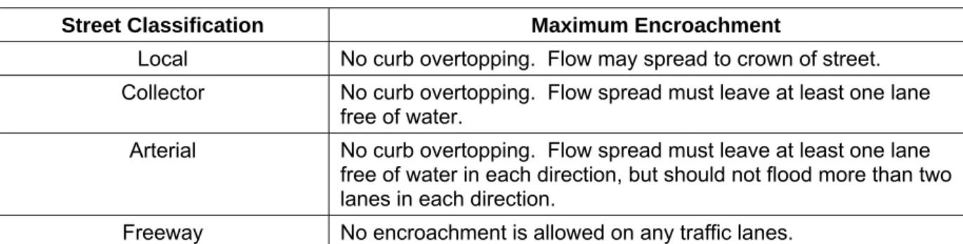
Certain design considerations must be taken into account in order to meet street drainage objectives. The primary design objective is to keep the spread (encroachment) of stormwater on the street below an acceptable value for a given return period of flooding. As mentioned previously, when stormwater collects on the street and flows down the gutter, the top width (or spread) of the water widens as more stormwater is collected. If left unchecked, the spread of water would eventually hinder traffic flow and possibly become hazardous (i.e., reduced skid resistance, hydroplaning, splash, etc.). Based on these considerations, the District has established encroachment (spread) standards for the minor storm event. These standards were given in the POLICY chapter and are repeated in Table ST-2 for convenience.
Table ST-2—Pavement Encroachment Standards for the Minor Storm
Street Classification Maximum Encroachment
Local No curb overtopping. Flow may spread to crown of street. Collector No curb overtopping. Flow spread must leave at least one lane
free of water.
Arterial No curb overtopping. Flow spread must leave at least one lane free of water in each direction, but should not flood more than two lanes in each direction.
Freeway No encroachment is allowed on any traffic lanes.
Standards for the major storm and street cross flows are also required. The major storm needs to be assessed to determine the potential for flooding and public safety. Cross flows also need to be regulated for traffic flow and public safety reasons. The District has established street inundation standards during the major storm event and allowable cross-street flow standards. These standards were given in the POLICY chapter and are repeated in Table ST-3 and Table ST-4 for convenience.
Table ST-3—Street Inundation Standards for the Major (i.e., 100-Year) Storm
Street Classification Maximum Depth and Inundated Area
Local and Collector Residential dwellings and public, commercial, and industrial buildings should be no less than 12 inches above the 100-year flood at the ground line or lowest water entry of the building. The depth of water over the gutter flow line should not exceed 18 inches.
Arterial and Freeway Residential dwellings and public, commercial, and industrial buildings should be no less than 12 inches above the 100-year flood at the ground line or lowest water entry of the building. The depth of water should not exceed the street crown to allow operation of emergency vehicles. The depth of water over the gutter flow line should not exceed 12 inches.
Table ST-4—Allowable Cross-Street Flow
Street Classification Initial Storm Flow Major (100-Year) Storm Flow
Local 6 inches of depth in cross pan. 18 inches of depth above gutter flow line.
Collector Where cross pans allowed,
depth of flow should not exceed 6 inches.
12 inches of depth above gutter flow line.
Arterial/Freeway None. No cross flow. Maximum depth
at upstream gutter on road edge of 12 inches.
Once an allowable spread (pavement encroachment) has been established for the minor storm, the placement of inlets can be determined. The inlets will remove some or all of the excess stormwater and thus reduce the spread. The placement of inlets is covered in Section 3.0. It should be noted that proper drainage design utilizes the full allowable capacity of the street gutter in order to limit the cost of inlets and storm sewers.
Another important design consideration is the frequency of occurrence of the minor storm. In other words, how often will the spread of stormwater reach or exceed the maximum encroachment limit. This is addressed by assigning a frequency (or recurrence interval) to the minor storm. The selection of a design frequency is based on many factors including street function, traffic load, vehicle speed, etc. The minor storm is generally between the 2-year and 10-year storm. The major storm is normally defined as the 100-year storm. The minor and major storm return periods are mandated by local governments. Two additional design considerations of importance in street drainage are gutter (channel) shape and street slope. Most urban streets contain curb and gutter sections. Various types exist which include spill shapes, catch shapes, curb heads, and roll gutters. The shape is chosen for functional, cost, or aesthetic reasons and does not dramatically affect the hydraulic capacity. Swales are common along some urban and semi-urban streets, and roadside ditches are common along rural streets. Their shapes are
important in determining hydraulic capacity and are covered in the next section.
2.3 Hydraulic Evaluation
Hydraulic computations are performed to determine the capacity of roadside swales and street gutters and the encroachment of stormwater onto the street. The design discharge is usually determined using the Rational method (covered in the next two sections). Stormwater runoff ends up in swales, roadside ditches and street gutters where the flow is unsteady and non-uniform. However, uniform, steady flow is usually assumed for the short period of time during peak flow conditions.
2.3.1 Curb and Gutter
Street slope can be divided into two components: longitudinal slope and cross slope. The longitudinal slope of the gutter essentially mimics the street slope. The hydraulic capacity of a gutter increases as the longitudinal slope increases. The District prescribes a minimum grade of 0.4% (Wright-McLaughlin 1969). The allowable flow capacity of the gutter on steep slopes is limited to provide for public safety. The cross (transverse) slope represents the slope from the street crown to the gutter section. A compromise is struck between large cross slopes that facilitate pavement drainage and small cross slopes for driver safety and comfort. The District prescribes a minimum cross slope of 1% for pavement drainage. Composite sections are often used with gutter cross slopes being steeper than street cross slopes to increase the gutter capacity.
The hydraulic evaluation of street capacity includes the following steps:
1. Calculate the theoretical street gutter flow capacity to convey the minor storm based upon the allowable spread defined in Table ST-2.
2. Calculate the theoretical street gutter flow capacity to convey the minor storm based upon the allowable depth defined Table ST-2.
3. Calculate the allowable street gutter flow capacity by multiplying the theoretical capacity (calculated in number 2) by a reduction factor. This reduction factor is used for safety
considerations. The lesser of the capacities calculated in step 1 and this step is the allowable street gutter capacity.
4. Calculate the theoretical major storm conveyance capacity based upon the road inundation criteria in Table ST-3. Reduce the major storm capacity by a reduction factor to determine the allowable storm conveyance capacity.
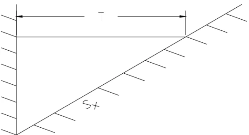
2.3.1.1 Gutters With Uniform Cross Slopes (i.e., Where Gutter Cross Slope = Street Cross Slope)
Since gutter flow is assumed to be uniform for design purposes, Manning’s equation is appropriate with a slight modification to account for the effects of a small hydraulic radius. For a triangular cross section
(Figure ST-1a), the Manning formula for gutter flow is written as: 3 / 8 2 / 1 3 / 5
56
.
0
T
S
S
n
Q
=
x L (ST-1)in which:
Q = calculated flow rate for the street (cfs)
n = Manning’s roughness coefficient, (typically = 0.016)
Sx = street cross slope for the street (ft/ft)
SL = longitudinal slope (ft/ft)
T = top width of flow spread (ft)
The flow depth, y, at the curb can be found using:
x
TS
y
=
(ST-2)Note that the flow depth must be less than the curb height during the minor storm based on Table ST-2. Manning’s equation can be written in terms of the flow depth, as:
3 8 2 1
56
.
0
y
S
nS
Q
L x=
(ST-3)The cross-sectional flow area, A, can be expressed as: 2
)
2
/
1
(
S
T
A
=
x (ST-4)The gutter velocity at peak capacity may be found from the continuity equation (V = Q/A). Triangular
gutter cross-section calculations are illustrated in Example 6.1.
2.3.1.2 Gutters With Composite Cross Slopes (i.e., Where Gutter Cross Slope ≠ Street Cross Slope)
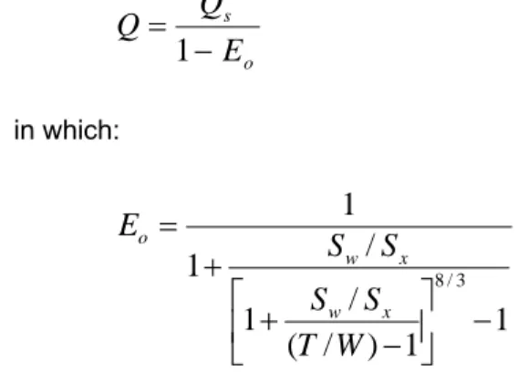
Gutters with composite cross slopes (Figure ST-1b) are often used to increase the gutter capacity. For a composite gutter section:
s
w
Q
Q
Q
=
+
(ST-5)in which:
Qw = flow rate in the depressed section of the gutter (cfs)
The Federal Highway Administration (FHWA 1996) provides the following equations for obtaining the flow rate in gutters with composite cross slopes. The theoretical flow rate, Q, is:
o s
E
Q
Q
−
=
1
(ST-6)in which:
1
1
)
/
(
/
1
/
1
1
3 / 8−
⎥
⎦
⎤
⎢
⎣
⎡
−
+
+
=
W
T
S
S
S
S
E
x w x wo (ST-7)
in which Sw is the gutter cross slope (ft/ft), and,
W
a
S
S
w=
x+
(ST-8)in which a is the gutter depression (feet) and W is width of the gutter (ft).
Figure ST-1b depicts all geometric variables. From the geometry, it can be shown that:
x
TS
a
y
=
+
(ST-9)and,
2
1
2
1
2aW
T
S
A
=
x+
(ST-10)in which y is the flow depth (at the curb) and A is the flow area. Composite cross-section gutter flow
calculations are illustrated in Examples 6.2 and 6.3.
2.3.1.3 Allowable Gutter Hydraulic Capacity
Stormwater flows along streets exert momentum forces on cars, pavement, and pedestrians. To limit the hazardous nature of heavy street flows, it is necessary to set limits on flow velocities and depths. As a result, the allowable gutter hydraulic capacity is determined as the lesser of:
T
A
Q
Q
=
(ST-11)or
F
A
R
Q
in which QA = allowable street hydraulic capacity, QT = street hydraulic capacity limited by the maximum
water spread, R = reduction factor, and QF = gutter capacity when flow depth equals allowable depth.
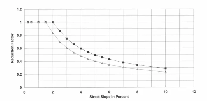
There are two sets of reduction factors developed for Denver metropolitan areas (Guo 2000b). One is for the minor event, and another is for the major event. Figure ST-2 shows that the reduction factor remains unity (1.0) for a street slope <1.5%, and then decreases as the street slope increases.
It is important for street drainage designs that the allowable street hydraulic capacity be used instead of the calculated gutter-full capacity. Thus, wherever the accumulated stormwater amount on the street is close to the allowable capacity, a street inlet shall be installed.
2.3.2 Swale Sections (V-Shaped With the Same or Different Side Slopes)
Swales are often used to convey runoff from pavement where curb and gutter sections are not used. It is very important that swale depths and side slopes be as shallow as possible for safety and maintenance reasons. Street-side swales are not the same as roadside ditches that can be considered part of a major drainageway system. Street-side swales serve as collectors of initial runoff and transport it to the nearest inlet or major drainageway. To be effective, they need to be limited to the velocity, depth, and cross-slope geometries considered acceptable. The following limitations shall apply to street-side swales:
• Maximum 2-year flow velocity = 3 ft/sec
• Maximum flow depth = 1.0 ft
• Maximum side slope of each side = 5H:1V.*
* Use of flatter side slopes is strongly recommended.
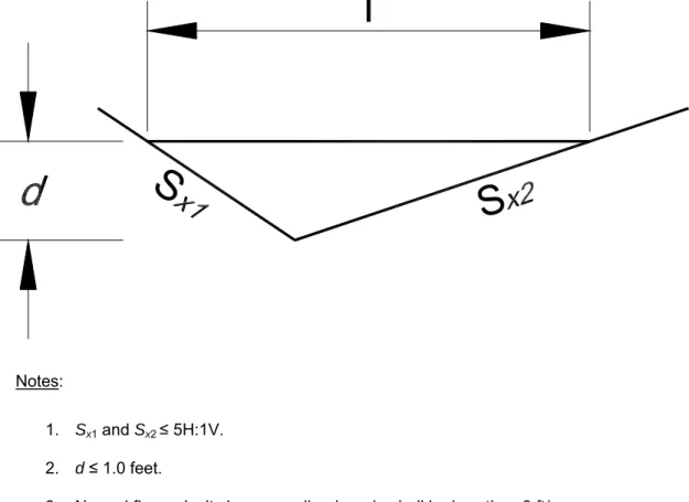
Swales generally have V-sections (Figure ST-3). Equation ST-1 can be used to calculate the flow rate in a V-section (if the section has a constant Manning’s n value) with an adjusted slope found using:
2 1
2 1
x x
x x x
S
S
S
S
S
+
=
(ST-13)in which:
Sx = adjusted side slope (ft/ft)
Sx1 = right side slope (ft/ft)
Sx2= left side slope (ft/ft)
Figure ST-3 shows the geometric variables.
Under no circumstances shall a street-side swale have a longitudinal slope steeper than 2%. Use grade control checks to control the grade if the adjacent street is steeper.
Note that the slope of roadside ditches and swales is often different than the adjacent street. The
hydraulic characteristics of the swale can therefore change from one location to another on a given swale. The flow depth and spread limitations of Tables ST-2 and ST-4 are also valid for swales and roadside ditches. There is no capacity reduction for safety considerations for roadside swales.
The designer is cautioned when using swales. If not properly designed and maintained, they can become a nuisance to the local residents.
Manning’s equation can be used to calculate flow characteristics.
2 1 3 2
49
.
1
L
S
AR
n
Q
=
(ST-14)in which:
Q = flow rate (cfs)
n = Manning’s roughness coefficient
A = flow area (ft2) R = A/P (ft)
P = wetted perimeter (ft) SL = longitudinal slope (ft/ft)
2.4 Major Storm Hydraulics 2.4.1 Purpose and Objectives
As previously mentioned, the primary objective of street drainage design is not to exceed the spread (encroachment) criteria during the minor storm event. Since larger storms do occur, it is prudent to determine the consequences of the major storm event. Table ST-3 lists the street inundation standards recommended by this Manual for the major storm event. Proper street design requires that the major
storm be assessed in the interest of public safety and to minimize the potential for flood damages.
2.4.2 Street Hydraulic Capacity
During major storms, streets typically become wide, open channels that convey stormwater flow in excess of the storm sewer capacity. Manning’s equation (Equation ST-14) is generally appropriate to determine flow depths and street capacities assuming uniform flow.
The general form of Manning’s equation is the most appropriate solution method for this situation since many different flow situations and channel shapes may be encountered. The allowable street capacity for a major storm is also subject to safety considerations using the reduction factor taken from Figure ST-2. Major storm street hydraulic capacity calculations are shown in Example 6.6.
Figure ST-1a—Typical Gutter Sections—Constant Cross Slope
Notes:
1. Sx1 and Sx2 ≤ 5H:1V. 2. d ≤ 1.0 feet.
3. Normal flow velocity in a grass-lined swale shall be less than 3 ft/sec during a 2-year storm.
4. Longitudinal grade of a grass-lined swale shall be less than 2%. Use grade control checks if adjacent street is steeper to limit the swale’s flow.
T
S
S
3.0 INLETS 3.1 Inlet Functions, Types and Appropriate Applications
Stormwater inlets are a vital component of the urban stormwater collection and conveyance system. Inlets collect excess stormwater from the street, transition the flow into storm sewers, and can provide maintenance access to the storm sewer system. They can be made of cast-iron, steel, concrete, and/or pre-cast concrete and are installed on the edge of the street adjacent to the street gutter or in the bottom of a swale.
Roadway geometrical features often dictate the location of pavement drainage inlets. In general, inlets are placed at all low points (sumps or sags) in the gutter grade, median breaks, intersections, and crosswalks. The spacing of inlets placed between those required by geometric controls is governed by the design flow spread (i.e., allowable encroachment). In other words, the drainage inlets are spaced so that the spread under the design (minor) storm conditions will not exceed the allowable flow spread (Akan and Houghtalen 2002).
There are four major types of inlets: grate, curb opening, combination, and slotted. Figure ST-4 depicts the four major types of inlets along with some associated geometric variables. Table ST-5 provides information on the appropriate application of the different inlet types along with advantages and disadvantages of each.
Table ST-5—Applicable Settings for Various Inlet Types
Inlet Type Applicable Setting Advantages Disadvantages
Grate Sumps and continuous grades (should be made bicycle safe)
Perform well over wide range of grades
Can become clogged Lose some capacity with increasing grade Curb-opening Sumps and continuous grades
(but not steep grades) Do not clog easily Bicycle safe Lose capacity with increasing grade Combination Sumps and continuous grades
(should be made bicycle safe) High capacity Do not clog easily More expensive than grate or curb-opening acting alone
Slotted Locations where sheet flow must
be intercepted. Intercept flow over wide section Susceptible to clogging
3.2 Design Considerations
Stormwater inlet design takes two forms: inlet placement location and inlet hydraulic capacity. As previously mentioned, inlets must be placed in sumps to prevent ponding of excess stormwater. On streets with continuous grades, inlets are required periodically to keep the gutter flow from exceeding the encroachment limitations. In both cases, the size and type of inlets need to be designed based upon their hydraulic capacity.
Inlets placed on continuous grades rarely intercept all of the gutter flow during the minor (design) storm. The effectiveness of the inlet is expressed as an efficiency, E, which is defined as:
Q
Q
E
=
i (ST-15)in which:
E = inlet efficiency
Qi = intercepted flow rate (cfs)
Q = total gutter flow rate (cfs)
Bypass (or carryover) flow is not intercepted by the inlet. By definition,
i
b
Q
Q
Q
=
−
(ST-16)in which:
Qb = bypass (or carryover) flow rate (cfs)
The ability of an inlet to intercept flow (i.e., hydraulic capacity) on a continuous grade generally increases with increasing gutter flow, but the capture efficiency decreases. In other words, even though more stormwater is captured, a smaller percentage of the gutter flow is captured. In general, the inlet capacity depends upon:
• The inlet type and geometry.
• The flow rate (depth and spread of water).
• The cross (transverse) slope.
• The longitudinal slope.
The hydraulic capacity of an inlet varies with the type of inlet. For grate inlets, the capacity is largely dependent on the amount of water flowing over the grate, the grate configuration and spacing, and the velocity of flow. For curb opening inlets, the capacity is largely dependent on the length of the opening, the flow velocity, street and gutter cross slope, and the flow depth at the curb. Local gutter depression along the curb opening helps boost the capacity. On the other hand, top slab supports can decrease the capacity. Combination inlets do not intercept much more than their grates alone if they are placed side by side and are of nearly equal lengths but are much less likely to clog. Slotted inlets function in a manner similar to curb opening inlets (FHWA 1996).
Inlets in sumps operate as weirs for shallow pond depths, but eventually will operate as orifices as the depth increases. A transition region exists between weir flow and orifice flow, much like a culvert. Grate
inlets and slotted inlets tend to clog with debris, so calculations should take that into account. Curb opening inlets tend to be more dependable for this reason.
3.3 Hydraulic Evaluation
The hydraulic capacity of an inlet is dependent on the type of inlet (grate, curb opening, combination, or slotted) and the location (on a continuous grade or in a sump). The methodology for determination of hydraulic capacity of the various inlet types is described in the following sections: (a) grate inlets on a continuous grade (Section 3.3.1), (b) curb opening inlets on a continuous grade (Section 3.3.2), (c) combination inlets on a continuous grade (Section 3.3.3), (d) slotted inlets on a continuous grade (Section 3.3.4), and (e) inlets located in sumps (Section 3.3.5).
3.3.1 Grate Inlets (On a Continuous Grade)
The capture efficiency of a grate inlet is highly dependent on the width and length of the grate and the velocity of gutter flow. If the gutter velocity is low and the spread of water does not exceed the grate width, all of the flow will be captured by the grate inlet. This is not normally the case during the minor (design) storm. The spread of water often exceeds the grate width and the flow velocity can be high. Thus, some water gets by the inlet. Water going over the grate may be capable of “splashing over” the grate, and usually little of the water outside the grate width is captured.
In order to determine the efficiency of a grate inlet, gutter flow is divided into two parts: frontal flow and side flow. Frontal flow is defined as that portion of the flow within the width of the grate. The portion of the flow outside the grate width is called side flow. By using Equation ST-1, the frontal flow can be evaluated and is expressed as:
(
)
(
[
2.671
1
W
T
Q
Q
w=
−
−
)
]
(ST-17)in which:
Qw = frontal discharge (flow within width W) (cfs)
Q = total gutter flow (cfs) found using Equation ST-1 W = width of grate (ft)
T = total spread of water in the gutter (ft)
It should be noted that the grate width is generally equal to the depressed section in a composite gutter section. Now by definition:
w
s
Q
Q
Q
=
−
(ST-18)Qs = side discharge (i.e., flow outside the depressed gutter or grate) (cfs)
The ratio of the frontal flow intercepted by the inlet to total frontal flow, Rf, is expressed as:
(
ow wi
f
Q
Q
V
V
R
=
=
1
.
0
−
0
.
09
−
)
forV
≥
V
o, otherwiseR
f= 1.0
(ST-19)in which:
Qwi= frontal flow intercepted by the inlet (cfs)
V = velocity of flow in the gutter (ft/sec) Vo = splash-over velocity (ft/sec)
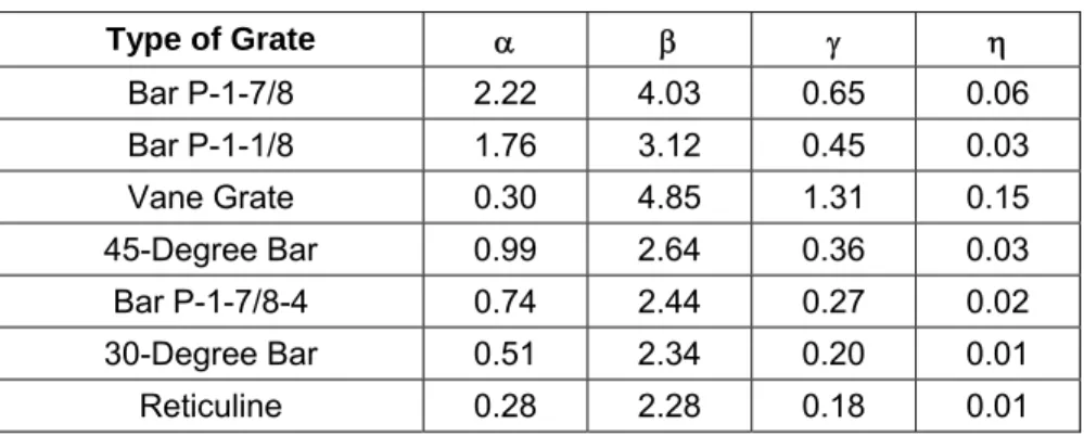
The splash-over velocity is defined as the minimum velocity causing some water to shoot over the grate. This velocity is a function of the grate length and type. The splash-over velocity can be determined using the empirical formula (Guo 1999):
3 2
e e
e
o
L
L
L
V
=
α
+
β
−
γ
+
η
(ST-20)in which:
Vo = splash-over velocity (ft/sec)
Le = effective unit length of grate inlet (ft)
η
γ
β
α
,
,
,
= constants from Table ST-6Table ST-6—Splash Velocity Constants for Various Types of Inlet Grates
Type of Grate α β γ η
Bar P-1-7/8 2.22 4.03 0.65 0.06
Bar P-1-1/8 1.76 3.12 0.45 0.03
Vane Grate 0.30 4.85 1.31 0.15
45-Degree Bar 0.99 2.64 0.36 0.03
Bar P-1-7/8-4 0.74 2.44 0.27 0.02
30-Degree Bar 0.51 2.34 0.20 0.01
The ratio of the side flow intercepted by the inlet to total side flow, Rs, is expressed as:
3 . 2
8 . 1
15
.
0
1
1
L
S
V
R
x s
+
=
(ST-21)in which:
V = velocity of flow in the gutter (ft/sec) L = length of grate (ft)
The capture efficiency, E, of the grate inlet may now be determined using:
(
Q
Q
)
R
(
Q
Q
R
E
=
f w+
s s) (ST-22)
Example 6.9 shows grate inlet capacity calculations.
3.3.2 Curb-Opening Inlets (On a Continuous Grade)
The capture efficiency of a curb-opening inlet is dependent on the length of the opening, the depth of flow at the curb, street cross slope and the longitudinal gutter slope (see Photograph ST-3). If the curb opening is long, the flow rate is low, and the longitudinal gutter slope is small, all of the flow will be captured by the inlet. This is not normally the case during the minor (design) storm. In fact, it is generally uneconomical to install a curb opening long enough to capture all of the flow. Thus, some water gets by the inlet, and the inlet efficiency needs to be determined.
Photograph ST-3—Gutter/street slope is a major design factor for both street and inlet capacity.
The hydraulics of curb opening inlets are less complicated than grate inlets. The efficiency, E, of a
curb-opening inlet is calculated as:
(
)
[
1.81
1
L
L
TE
=
−
−
]
forL < L
T, otherwiseE
= 1.0
(ST-23)in which:
L = installed (or designed) curb-opening length (ft)
LT = curb-opening length required to capture 100% of gutter flow (ft)
and, for a curb-opening inlet that is not depressed,
6 . 0 3 . 0 42 . 0
1
6
.
0
⎟⎟
⎠
⎞
⎜⎜
⎝
⎛
=
x L TnS
S
Q
L
(ST-24)in which:
Q = gutter flow (cfs)
SL = longitudinal street slope (ft/ft)
Sx = steel cross slope (ft/ft)
n = Manning’s roughness coefficient
For a depressed curb-opening inlet,
6 . 0 3 . 0 42 . 0
1
6
.
0
⎟⎟
⎠
⎞
⎜⎜
⎝
⎛
=
e L TnS
S
Q
L
(ST-25)The equivalent cross slope, Se, can be determined from
o x e
E
W
a
S
S
=
+
(ST-26)in which a = gutter depression and W = depressed gutter section as shown in Figure ST-1b. The ratio of
the flow in the depressed section to total gutter flow, Eo, can be calculated from Equation ST-7. See
Examples 6.8 and 6.9 for curb-opening inlet calculations.
3.3.3 Combination Inlets (On a Continuous Grade)
Combination inlets take advantage of the debris removal capabilities of a curb-opening inlet and the capture efficiency of a grate inlet. If the grate and the curb opening are side-by-side and of approximately equal length, the interception capacity is found by assuming the grate acts alone. If all or part of the curb-opening inlet lies upstream from the grate (a desirable configuration), the inlet capacity is enhanced by
the upstream curb-opening capacity. The appropriate equations have already been presented, but Example 6.10 illustrates the procedure.
3.3.4 Slotted Inlets (On a Continuous Grade)
Slotted inlets can generally be used to intercept sheet flow that is crossing the pavement in an undesirable location. Unlike grate inlets, they have the advantage of intercepting flow over a wide section. They do not interfere with traffic operations and can be used on both curbed and uncurbed sections. Like grate inlets, they are susceptible to clogging.
Slotted inlets function like a side-flow weir, much like curb-opening inlets. The FHWA (1996) suggests the hydraulic capacity of slotted inlets closely corresponds to curb-opening inlets if the slot openings exceed 1.75 inches. Therefore, the equations developed for curb-opening inlets (Equations ST-23 through ST-26) are appropriate for slotted inlets.
3.3.5 Inlets Located in Sumps
All of the stormwater excess that enters a sump (i.e., a depression or low point in grade) must pass through an inlet to enter the stormwater conveyance system. If the stormwater is laden with debris, the inlet is susceptible to clogging. The ponding of water is a nuisance and could be hazardous. Therefore, the capacity of inlets in sumps must account for this clogging potential. Grate inlets acting alone are not recommended for this reason. Curb-opening inlets are more appropriate, as are combination inlets. Photograph ST-4 shows a curb opening inlet in a sump condition.
Photograph ST-4—Inlets that are located in street sags and sumped can be highly efficient.
As previously mentioned, inlets in sumps function like weirs for shallow depths, but as the depth of stormwater increases, they begin to function like an orifice. Orifice and weir flows have been exhaustively
studied. Equations are readily available to compute requisite flow rates. However, the transition from weir flow to orifice flow takes place over a relatively small range of depth that is not well defined. The FHWA provides guidance on the transition region based on significant testing.
The hydraulic capacity of grate, curb-opening, and slotted inlets operating as weirs is expressed as:
5 . 1
d
L
C
Q
i=
w w (ST-27)in which:
Qi= inlet capacity (cfs)
Cw= weir discharge coefficient
Lw = weir length (ft)
d = flow depth (ft)
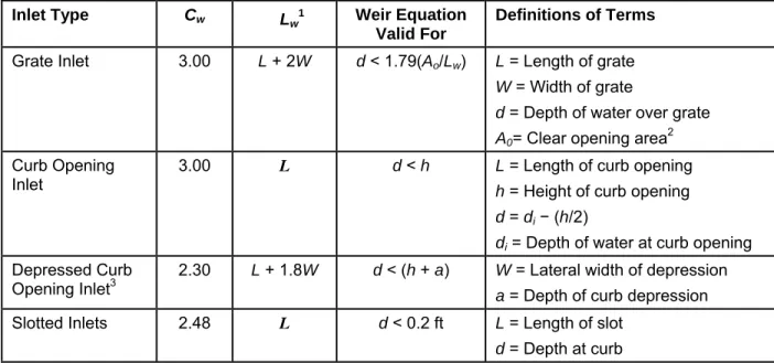
Values for Cw and Lw are presented in Table ST-7 for various inlet types. Note that the expressions given
for curb-opening inlets without depression should be used for depressed curb-opening inlets if L > 12 feet.
The hydraulic capacity of grate, curb-opening, and slotted inlets operating as orifices is expressed as:
(
)
0.52
gd
A
C
Q
i=
o o (ST-28)in which:
Qi= inlet capacity (cfs)
Co = orifice discharge coefficient
Ao = orifice area (ft
2)
d = characteristic depth (ft) as defined in Table ST-7
g = 32.2 ft/sec2
Values for Co and Ao are presented in Table ST-7 for different types of inlets.
Combination inlets are commonly used in sumps. The hydraulic capacity of combination inlets in sumps depends on the type of flow and the relative lengths of the curb opening and grate. For weir flow, the capacity of a combination inlet (grate length equal to the curb opening length) is equal to the capacity of the grate portion only. This is because the curb opening does not add any length to the weir equation (Equation ST-27). If the curb opening is longer than the grate, the capacity of the additional curb length should be added to the grate capacity. For orifice flow, the capacity of the curb opening should be added to the capacity of the grate.
Table ST-7—Sag Inlet Discharge Variables and Coefficients
(Modified From Akan and Houghtalen 2002)
Inlet Type Cw Lw1 Weir Equation
Valid For
Definitions of Terms
Grate Inlet 3.00 L + 2W d < 1.79(Ao/Lw) L = Length of grate
W = Width of grate
d = Depth of water over grate A0= Clear opening area
2 Curb Opening
Inlet 3.00 L d < h Lh = Length of curb opening = Height of curb opening
d = di− (h/2)
di = Depth of water at curb opening
Depressed Curb
Opening Inlet3 2.30 L + 1.8W d < (h + a) W = Lateral width of depression
a = Depth of curb depression
Slotted Inlets 2.48 L d < 0.2 ft L = Length of slot d = Depth at curb
1 The weir length should be reduced where clogging is expected.
2 Ratio of clear opening area to total area is 0.8 for P-1-7/8-4 and reticuline grates, 0.9 for P-1-7/8 and 0.6 for P-1-1/8 grates. Curved vane and tilt bar grates are not recommended at sag locations.
3 If
L > 12 ft, use the expressions for curb opening inlets without depression.
Co A0
4
Orifice Equation Valid for
Definition of Terms
Grate Inlet 0.67 Clear opening
area5
d > 1.79(Ao /Lw) d = Depth of water over grate
Curb Opening Inlet (depressed or undepressed, horizontal orifice throat6)
0.67 (h)(L) di > 1.4h d = di – (h/2)
di = Depth of water at curb opening
h = Height of curb opening
Slotted Inlet 0.80 (L)(W) d > 0.40 ft L = Length of slot
W = Width of slot
d = Depth of water over slot
4 The orifice area should be reduced where clogging is expected.
5 The ratio of clear opening area to total area is 0.8 for P-1-7/8-4 and reticuline grates, 0.9 for P-1-7/8 and 0.6 for P-1-1/8 grates. Curved vane and tilt bar grates are not recommended at sag locations. 6 See Figure ST-5 for other types of throats.
3.3.6 Inlet Clogging
Inlets are subject to clogging effects (see Photographs ST-5 and ST-6). Selection of a clogging factor reflects the condition of debris and trash on the street. During a storm event, street inlets are usually
loaded with debris by the first-flush runoff volume. As a common practice for street drainage, 50% clogging is considered for the design of a single grate inlet and 10% clogging is considered for a single curb-opening inlet. Often, it takes multiple units to collect the stormwater on the street. Since the amount of debris is largely associated with the first-flush volume in a storm event, the clogging factor applied to a multiple-unit street inlet should be decreased with respect to the length of the inlet. Linearly applying a single-unit clogging factor to a multiple-unit inlet leads to an excessive increase in length. For instance, a six-unit inlet under a 50% clogging factor will function as a three-unit inlet. In fact, continuously applying a 50% reduction to the discharge on the street will always leave 50% of the residual flow on the street. This means that the inlet will never reach a 100% capture and leads to unnecessarily long inlets.
Photograph ST-5—Clogging is an important consideration when designing inlets.
With the concept of first-flush volume, the decay of clogging factor to curb opening length is described as (Guo 2000a):
∑
= = − −=
=
+
+
+
+
+
=
i Ni o i o o N o o o o
N
KC
e
N
C
C
e
C
e
C
e
eC
C
N
C
1 1 1 3 2)
...
(
1
(ST-29) in which:C = multiple-unit clogging factor for an inlet with multiple units
Co = single-unit clogging factor
e = decay ratio less than unity, 0.5 for grate inlet, 0.25 for curb-opening inlet N = number of units
K = clogging coefficient from Table ST-8
Table ST-8—Clogging Coefficients to Convert Clogging Factor From Single to Multiple Units1
N= 1 2 3 4 5 6 7 8 >8
Grate Inlet (K) 1 1.5 1.75 1.88 1.94 1.97 1.98 1.99 2
Curb Opening (K)
1 1.25 1.31 1.33 1.33 1.33 1.33 1.33 1.33 1 This table is generated by Equation ST-29 with
e = 0.5 and e = 0.25.
When N becomes large, Equation ST-29 converges to:
)
1
(
e
N
C
C
o−
=
(ST-30)For instance, when e = 0.5 and Co = 50%, C = 1.0/N for a large number of units, N. In other words, only
the first unit out of N units will be clogged. Equation ST-30 complies with the recommended clogging factor for a single-unit inlet and decays on the clogging effect for a multiple-unit inlet.
The interception of an inlet on a grade is proportional to the inlet length, and in a sump is proportional to the inlet opening area. Therefore, a clogging factor shall be applied to the length of the inlet on a grade as:
L
C
L
e=
(
1
−
)
(ST-31)in which Le = effective (unclogged) length. Similarly, a clogging factor shall be applied to the opening area
A
C
A
e=
(
1
−
)
(ST-32)in which:
Ae = effective opening area
A = opening area
3.4 Inlet Location and Spacing on Continuous Grades 3.4.1 Introduction
Locating (or positioning) stormwater inlets rarely requires design computations. They are simply required in certain locations based upon street design considerations, topography (sumps), and local ordinances. The one exception is the location and spacing of inlets on continuous grades. On a long, continuous grade, stormwater flow increases as it moves down the gutter and picks up more drainage area. As the flow increases, so does the spread. Since the spread (encroachment) is not allowed to exceed some specified maximum, inlets must be strategically placed to remove some of the stormwater from the street. Locating these inlets requires design computations by the engineer.
3.4.2 Design Considerations
The primary design consideration for the location and spacing of inlets on continuous grades is the spread limitation. This was addressed in Section 2.2. Table ST-2 lists pavement encroachment standards for minor storms in the Denver metropolitan area.
Proper design of stormwater collection and conveyance systems makes optimum use of the conveyance capabilities of street gutters. In other words, an inlet is not needed until the spread reaches its allowable limit during the design (minor) storm. To place an inlet prior to that point on the street is not economically efficient. To place an inlet after that point would violate the encroachment standards. Therefore, the primary design objective is to position inlets along a continuous grade at the locations where the allowable spread is about to be exceeded for the design storm.
3.4.3 Design Procedure
Based on the encroachment standard and street geometry, the allowable street hydraulic capacity can be determined using Equation ST-11 or Equation ST-12. This flow rate is then equated to some hydrologic technique (equation) that contains drainage area. In this way, the inlet is positioned on the street so that it will service the requisite drainage area. The process of locating the inlet is accomplished by trial-and-error. If the inlet is moved downstream (or down gutter), the drainage area increases. If the inlet is moved upstream, the drainage area decreases.
The hydrologic technique most often used in urban drainage design is the Rational method. The Rational method was discussed in the RUNOFF chapter. The Rational equation, repeated here for convenience,
is:
CIA
Q
=
(ST-33)in which:
Q = peak discharge (cfs)
C = runoff coefficient described in the RUNOFF chapter
I = design storm rainfall intensity (in/hr) described in the RAINFALL chapter A = drainage area (acres)
As previously mentioned, the peak discharge is found using the allowable spread and street geometry. The runoff coefficient is dependent on the land use as discussed in the RUNOFF chapter. The rainfall intensity is discussed in the RAINFALL chapter. The drainage area is the unknown variable to be solved. Once the first inlet is positioned along a continuous grade, an inlet type and size can be specified. The first inlet’s hydraulic capacity is then assessed. Generally, the inlet will not capture all of the gutter flow. In fact, it is uneconomical to size an inlet (on continuous grades) large enough to capture all of the gutter flow. Instead, some carryover flow is expected. This practice reduces the amount of new flow that can be picked up at the next inlet. However, each inlet should be positioned at the location where the allowable spread is about to reach its allowable limit.
The gutter discharge for inlets, other than the first inlet, consists of the carryover from the upstream inlet plus the stormwater runoff generated from the intervening local drainage area. The carryover flow from the upstream inlet is added to the peak flow rate obtained from the Rational method for the intervening local drainage area. The resulting peak flow is approximate since the carryover flow peak and the local runoff peak do not necessarily coincide.
4.0 STORM SEWERS 4.1 Introduction
Once stormwater is collected from the street surface by an inlet, it is directed into the storm sewer system. The storm sewer system is comprised of inlets, pipes, manholes, bends, outlets, and other appurtenances. The stormwater passes through these components and is discharged into a stormwater management device (e.g., infiltration trench, stormwater pond, constructed wetland, etc.) to mitigate adverse downstream effects or discharged directly to a natural or constructed watercourse. Stormwater management devices are constructed to reduce the peak discharge, decrease the volume of runoff, and/or improve the water quality.
Apart from inlets, manholes are the most common appurtenance in storm sewer systems. Their primary functions include:
• Providing maintenance access.
• Providing ventilation.
• Serving as junctions when two or more pipes merge.
• Providing flow transitions for changes in pipe size, slope, and alignment.
Manholes are generally made of pre-cast or cast-in-place reinforced concrete. They are typically 4 to 5 feet in diameter and are required at regular intervals, even in straight sections, for maintenance reasons. Standard size manholes cannot accommodate large pipes, so junction chambers are used for that application.
Other appurtenances are not as common as manholes, but serve vital functions. Occasionally, bends and transitions are accomplished without manholes, particularly for large pipe sizes. These sections provide gradual transitions in size or alignment to minimize energy losses. Outlet structures are transitions from pipe flow into open channel flow or still water (e.g., ponds, lakes, etc.). Their primary function is to minimize erosion in the receiving water body. Flow splitters separate incoming flow and send it in two or more directions. Flow deflectors are used to minimize energy losses in manholes, junction chambers, and flow splitters. Flap gates are placed on outlets to prevent backflow in areas subject to high tailwater or flood flow.
4.2 Design Process, Considerations, and Constraints
The design of a storm sewer system requires a large data collection effort. The data requirements in the proposed service area include topography, drainage boundaries, soil types, and locations of any existing storm sewers, inlets, and manholes. In addition, identification of the type and location of other utilities is
necessary. Alternative layouts of a new system (or modifications to an existing system) can be investigated using this data.
Alternative system layouts rely largely on street right-of-ways and topography. Most layouts are dendritic (tree) networks that follow the street pattern. Dendritic networks collect stormwater from a broad area and tend to converge in the downstream direction. Looping networks shall be avoided because of their complex hydraulics and potentially higher cost. Each layout should contain inlet and manhole locations, drainage boundaries serviced by the inlets, storm sewer locations, flow directions, and outlet locations. A final layout selection is made from the viable alternatives based on likely system performance and cost. Once a final layout is chosen, storm sewers are sized using hydrologic techniques (to determine peak flows) and hydraulic analysis (to determine pipe capacities). This is accomplished by designing the upstream pipes first and moving downstream. Pipes sizes smaller than 15 inches are not recommended for storm sewers. Pipes generally increase in size moving downstream since the drainage area is
increasing. It is not good design practice to decrease the pipe size moving downstream, even if a steeper slope is encountered that will provide sufficient capacity with a smaller pipe. The potential for clogging is always a concern.
Storm sewers are typically sized to convey the minor storm without surcharging using normal flow techniques. In other words, the flow is in a pipe that is flowing just full determined by openchannel
hydraulics calculations.
The minor storm is defined by the return interval that usually varies from the 2-year to the 10-year storm depending on the importance of the infrastructure being served. Refer to the POLICY chapter for guidance regarding selection of the design storm.
Manholes are located in the system prior to and in conjunction with pipe design. Most manhole locations are dictated by proper design practices. For example, manholes are required whenever there is a change in pipe size, alignment, or slope. In addition, manholes are required at pipe junctions. Manholes are also required along straight sections of pipe for maintenance purposes. The distance between manholes is dependent on pipe size. The invert of a pipe leaving a manhole should be at least 0.1 foot lower than the incoming pipe to ensure positive low flows through the manhole. Whenever possible, match the crown of the pipe elevations when the downstream pipe is larger to minimize backwater effects on the upstream pipe.
Once storm sewers are sized and manhole locations are determined, the performance of the sewer system must be evaluated using energy grade line calculations starting at the downstream terminus of the system. As stormwater flows through the storm sewer system, it encounters many flow transitions. These transitions include changes in pipe size, slope, and alignment, as well as entrance and exit conditions. All of these transitions produce energy losses, usually expressed as head losses. These
losses must be accounted for to ensure that inlets and manholes do not surcharge to a significant degree (i.e., produce street flooding). This is accomplished using hydraulic grade line (HGL) calculations as a check on pipe sizes and system losses. If significant surcharging occurs, the pipe sizes should be increased. High tailwater conditions at the storm sewer outlet may also produce surcharging. This can also be accounted for using HGL calculations.
4.3 Storm Sewer Hydrology 4.3.1 Peak Runoff Prediction
The Rational method is commonly used to determine the peak flows that storm sewers must be able to convey. It is an appropriate method due to the small drainage areas typically involved. It is also relatively easy to use and provides reasonable estimates of peak runoff. The total drainage area contributing flow to a particular storm sewer is often divided up into smaller subcatchments. The Rational method is described in the RUNOFF chapter of this Manual.
The first pipe in a storm sewer system is designed using Equation ST-33 to determine the peak flow. Downstream pipes receive flow from the upstream pipes as well as local inflows. The Rational equation applied to the downstream pipes is:
∑
=
=
nj
j j
p
I
C
A
Q
1
(ST-34)
in which:
I = design rainfall average intensity, over the time of concentration Tc (in/hr)
n = number of subareas above the stormwater pipe Cj = runoff coefficient of subarea j
Aj = drainage area of subarea j (acres)
In using this equation, it is evident that the peak flow changes at each design point since the time of concentration, and thus the average intensity, changes at each design point. It is also evident that the time of concentration coming from the local inflow may differ from that coming from upstream pipes. Normally, the longest time of concentration is chosen for design purposes. If this is the case, all of the subareas above the design point will be included in Equation ST-34, and it usually produces the largest peak flow. On rare occasions, the peak flow from a shorter path may produce the greater peak discharge if the downstream areas are heavily developed. It is good practice to check all alternative flow paths and tributary areas to determine the tributary zone that produces the biggest design flow.
4.4 Storm Sewer Hydraulics (Gravity Flow in Circular Conduits) 4.4.1 Flow Equations and Storm Sewer Sizing
Storm sewer flow is usually unsteady and non-uniform. However, for design purposes it is assumed to be steady and uniform at the peak flow rate. Therefore, Manning’s equation is appropriate, which can be stated as:
2 1 3 2
49
.
1
f
S
AR
n
Q
=
(ST-35)in which:
Q = flow rate (cfs)
n = Manning’s roughness factor A = flow area (ft2)
R = hydraulic radius (ft)
Sf= friction slope (normally the storm sewer slope) (ft/ft)
For full flow in a circular storm sewer,
4
2
D
A
A
=
f=
π
(ST-36)4
D
R
R
=
f=
(ST-37)in which:
D = pipe diameter
Af = flow area at full flow (ft2)
Rf = hydraulic radius at full flow (ft)
If the flow is pressurized (i.e., surcharging at the inlets or manholes is occurring), Sf≠So where So is the
longitudinal bottom slope of the storm sewer. Design of storm sewers assumes just full flow, a reference
condition referring to steady, uniform flow with a flow depth, y, nearly equal to the pipe diameter, D. Just full flow discharge, Qf , is calculated using:
2 1 3 2
49
.
1
o f f
f
A
R
S
n
Computations of flow characteristics for partial depths in circular pipes are tedious. Design aids like Figure ST-6 are very helpful when this is necessary.
Storm sewers are sized to flow just full (i.e., as open channels using nearly the full capacity of the pipe). The design discharge is determined first using the Rational equation as previously discussed, then the Manning’s equation is used (with Sf = So) to determine the required pipe size. For circular pipes,
8 3
16
.
2
⎥
⎥
⎦
⎤
⎢
⎢
⎣
⎡
=
o p rS
nQ
D
(ST-39)in which Dr is the minimum size pipe required to convey the design flow and Qp is peak design flow.
However, the pipe diameter that should be used in the field is the next standard pipe size larger than Dr.
The typical process proceeds as follows. Initial storm sewer sizing is performed first using the Rational equation in conjunction with Manning’s equation. The Rational equation is used to determine the peak discharge that storm sewers must convey. The storm sewers are then initially sized using Manning’s equation assuming uniform, steady flow at the peak. Finally, these initial pipe sizes are checked using the energy equation by accounting for all head losses. If the energy computations detect surcharging at manholes or inlets, the pipe sizes are increased.
4.4.2 Energy Grade Line and Head Losses
Head losses must be accounted for in the design of storm sewers in order to find the energy grade line (EGL) and the hydraulic grade line (HGL) at any point in the system. The FHWA (1996) gives the following equation as the basis for calculating the head losses at inlets, manholes, and junctions (hLM, in
feet):
⎟⎟
⎠
⎞
⎜⎜
⎝
⎛
=
g
V
C
C
C
C
C
K
h
o B p Q d D o LM2
2 in which:Ko = initial loss coefficient
Vo = velocity in the outflow pipe (ft/sec)
g = gravitational acceleration (32.2 ft/sec2)
CD, Cd, CQ, Cp, and CB = correction factors for pipe size, flow depth, relative flow, plunging flow
and benching
However, this equation is valid only if the water level in the receiving inlet, junction, or manhole is above the invert of the incoming pipe. Otherwise, another protocol has to be used to calculate head losses at