TECHNICAL UNIVERSITY OF CLUJ-NAPOCA
ACTA TECHNICA NAPOCENSIS
Series: Applied Mathematics, Mechanics, and Engineering Vol. 62, Issue III, September, 2019
AUTOMATIC VISUAL SERVOING CONTROL SYSTEM FOR
INDUSTRIAL ROBOTS IN ARBITRARY WORK AREAS BASED ON M-
PBVS TECHNIQUE
Josue LOPEZ-LEYVA, Miguel PONCE-CAMACHO, Ariana TALAMANTES-ALVAREZ, Raul RAMOS-GARCIA, Sergio ROJAS-ARROYO, Victor RAMOS-GARCIA, Arturo
ARVIZU-MONDRAGON, Joel SANTOS-AGUILAR
Abstract: A visual servoing control system implemented in a SCARA robot based on an optimized kinematic algorithm in order to reduce the manufacturing and processing time in arbitrary work areas is presented. The robot uses two cameras for performing the calibration in real-time automatic way and determining the complete workspace and position allowed for the effector based on a novel modification of the Position/pose-based technique without pre-planned task. Finally, the results show that the time for initial calibration is drastically reduced and the control system planning optimal trajectories considering obstacles in the complete workspace.
Key words: control system, trajectory planning, mapping work area, visual servoing system, optimized system
1. INTRODUCTION
Nowadays, Visual Servoing (VS) techniques are more frequently being used in the control of robot manipulators using visual perception of the robot mechanical structure (e.g. final effector), workpiece location and complete workspace [1,2]. On the other hand, conventional manipulators present several issues such as the initial configuration (i.e. manual teaching of robot positions or automatic pre-planned task) for particular work conditions (e.g. workspace limited, obstacles in the workspace, etc.), among others [3,4]. Thus, conventional robots can increase the manufacturing-processing time with a high dependency on humans, leading to a non-desired cost-effect in a dynamical industrial sector. Moreover, visual servoing robots reduce drastically the high human dependency given a priori knowledge of coordinates of its workpieces and workspace. Therefore, these are a versatile solution as a countermeasure for the trade-off mentioned [5,6].
Although there are exist two configurations of the effector and the camera (end-point open / closed-loop control) relate to the camera position, the industrial needs impose specific modifications according the industrial process [7,8]. Some proposes uses two views of the same object as input signals to a Convolutional Neural Network (CNN) and fuzzy Q-learning but it require high-end digital processing and in some cases they are not suitable for industrial application that requires reduced processing time [9,10].
In addition, some applications use an eye-in- hand camera sensor [11]; however, the dynamical and velocity of the robot affects the performance of the eye-in-hand sensor. In fact, many visual servoing control systems are not suitable for real industrial application.
2. ROBOT DESIGN AND CONTROL SYSTEM BACKGROUND
experimental set-up. In particular, the parameters Denavit - Hartenberg (DH) are needed for calculate the kinematic and dynamic, also the center of mass is necessary for the fastening of the entire structure. The simplified model of direct kinematics for the robot is:
(1)
, where, x and y represents the location of the final tool, l1 and l2 are the distances of the links,
q1 and q2 are the rotational position of the
motors. The Jacobian matrix (J(q)) of the robot results in:
(2)
Here, v and w are the lineal and angular speed, respectively [12,13]. Therefore:
(3 )
Basically, the automatic visual servoing control system uses the algorithm presented in [10] for two principal objectives: 1) Determination of the complete arbitrary workspace of the robot without pre-planned tasks, and 2) Establishment of the optimal trajectory for movements of the final effector from an initial (p1) point to a final point (p2) with / without obstacles.
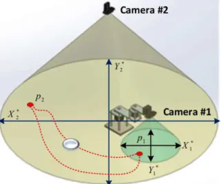
With respect to the image and framestore based on the data and address, many processes are needed. The image capture takes into account the illumination, surface reflectance, spectral characteristics and color temperature for different material and sensors, among other important factors [11]. Based on the last, the system proposed in this paper consider a strict control of such variables in an industrial environment. Thus, the perception of the real dimension (workspace) is needed, therefore, the Figure 1 shows the aerial view of the Camera #2 that allows modeling the robot workspace. At
the same time, the Camera #1 is used to increase the operation accuracy. Regarding the planes (axis) of the cameras and image plane coordinate systems, some parameters are needed to define: X and Y parameters represent the real directions corresponding to the image plane X*1,2 and Y*1,2
directions for each camera, respectively (i.e. coordinates of a point on the image plane or projective-perspective transform). Those equations can now be written in terms of pixel coordinates as:
(4)
(5)
Here, αx and αy are the horizontal and vertical
scale factors, respectively, (X0, Y0) is the pixel coordinate of the principal axis defined earlier, world coordinates (x,y,z) and f is the object view point. In addition, the original image function I(x,y) is sampled by the discrete CCD (Charge-Coupled Device,) to form the signal I(i,j), where i and j are the pixel coordinates [14]. The Nyquist period is 2 pixels, so fine image detail, that with a period of less than 2 pixels
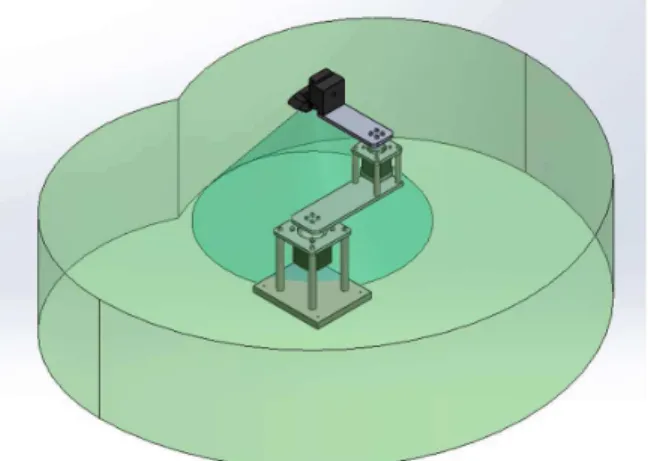
Fig. 1. SCARA robot designed and manufactured for implemented the visual control system and optimized
kinematic algorithm and Complete workspace. Next, the particular position information based on X*1,2 and Y*1,2 is used by the optimized
Position/pose-based (MPBVS) technique is used for controlling the position of each degree of freedom of the robot and increase the accuracy using two cameras. Figure 2 shows the principal interface of the software development in .Net using a USB-Camera (1280 x 720), where diverse circles define the following process: 1) Camera select, 2) Image capture, 3) object color select, 4) position coordinate (pixels), 5) real position of the object.
Fig. 2. Principal interface of the software .Net. The robot is auto-calibrated as an initial task when the complete system is fixed in a particular area in the industry. Figure 3 shows the first position of the calibration process, where the robot localizes the maximum vertical point in its workspace. Next, it localizes the maximum horizontal point (related with X0 and Y0,
respectively), followed for minimum point in each axis.
As Figure 3 shows, many red points present the path of the final effector, in particular, 200 intermediate point between the initial and final point of the trajectory planned by the visual control system.
Fig, 3. Automatic calibrating of the SCARA robot for vertical axis.
Fig. 4. Automatic calculation of the real position of the object.
Fig. 5 shows the robot movements considering the visual perception of both cameras in order to determine in an initial way the workspace available for particular industry process. Although the Camera #2 can visualize an initial workspace available, our control system requires the information of the Camera #1 for increase the accuracy of the effector and obstacles positions.
Fig. 5. Simultaneous visual inspection of both cameras in order to determine the workspace.
3. RESULTS AND DISCUSSION
px and py, respectively) was measuring based in
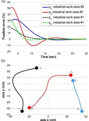
an initial location of the final effector. The results show that the final effector shows a greater position error due to the initial arbitrary position, mainly for the industrial work area #2. In addition, the time required for the complete calibration setting is 15 and 25 seconds approximately for work area #2 and #1, respectively. As Figure 6a) shows, the initial position error is variable according to the initial position of the effector in the quadrants (Q1, Q2, Q3 and Q4) that the Camera #2 monitors. Thus, the position error is from 19% up to 52 %, although negative position error is possible. In addition, Fig. 6a) shows that there are exist some negative position error due to the algorithm used. This is in order to determine a secure region for external limit of each work area, although is possible delete the negative values. On the other hand, Fig. 6b) shows the real-time tracing of trajectories of the final effector considering different conditions in the WAs.
Fig. 6. a) Time required for setting of the robot in two different industrial work area without obstacles, b) Trajectories determined by the automatic visual serving
control system with different conditions of the WA. Black and red traces consider an obstacle; blue trace not
consider exists an obstacle.
The figure shows the complete workspace detected by the Camera #2, 80 x 80 cm, from -40 up to +-40 cm per axis. In particular, two trajectories were determined by the visual servoing control in presence of obstacles; therefore, the optimum trajectory is not a pseudo direct or straight line. On the other hand, the trajectory determined without consider obstacles is pseudo direct. Finally, the Table 1 shows the complete performance of automatic visual servoing control system using the optimized kinematic algorithm. The quadrant shown represent the initial position of the final effector (e.g. initial position in quadrant 1 (Q1)). Therefore, the automatic visual servoing control system allows mapping the WA #1 without obstacles in a time lapse from 13.2 up to 16.1 seconds. However, the same WA with obstacles requires 23.2 seconds maximum. On the other hand, the WA #2 requires more calibration time for without / with obstacles conditions.
Table 1 Calibration time required for mapping the work area
4. CONCLUSION
systems. In addition, due to the environmental space conditions controlled of the work area, the visual servoing control system is based on the color of the targets and obstacles, however, a modeling error and noise in image feature measurements are necessaries for other particular industrial applications [15].
5. REFERENCES
[1] Shu, T. Gharaaty, S. Xie, W., “Dynamic path tracking of industrial robots with high accuracy by visual servoing”, 12th IEEE Conference on Industrial Electronics and Applications (ICIEA), pp. 968 – 973, Cambodia, June 2017. [2] Chen, S. Y., “Kalman Filter for Robot
Vision: A Survey”, Transactions on Industrial Electronics, vol. 59, no. 11, 2012, pp. 4409 – 4420.
[3] Chiaverini, S., Siciliano, B., Villani, L., “A survey of robot interaction control
schemes with experimental
comparison”, Transactions on Mechatronics, vol. 4, no. 3, 1999, pp. 273 – 285.
[4]Faulwasser, T., Weber, T., Zometa, P., Findeisen, R., “Implementation of Nonlinear Model Predictive Path-Following Control for an Industrial Robot”, Transactions on Control Systems Technology, vol. 25, no. 4, 2017, pp. 1505 – 1511.
[5] Ferreira, A., Cassier, C., Hirai, S., “Automatic microassembly system assisted by vision servoing and virtual reality”, Transactions on Mechatronics, vol. 9, no. 2, 2004, pp. 321 – 333. [6] Rastegarpanah, A., Marturi, N., Stolkin, R.,
“Autonomous vision-guided bi-manual grasping and manipulation”, in Workshop on Advanced Robotics and its Social Impacts (ARSO), pp. 1- 7, USA, March, 2017.
[7] Tsay, T. I. J., Lee, M. K., Wang, G. L., Hsu, M. S., Lai, C. H., “Robotic eye/arm coordination via visual servoing”, in Procc of the International Conference on Control Applications, pp. 742 – 747, UK, september 2002.
[8] Domova, V., Zoric, G., “Towards Effective Industrial Robot Fleet Visualization for Remote Service Applications”, in International Conference on Enabling Technologies: Infrastructure for Collaborative Enterprises (WETICE), pp. 185 – 190, Poland, August 2017. [9] Kumar, G., Pandya, H., Gaud, A., Madhava
Krishna, K., “Pose induction for visual servoing to a novel object instance”, International Conference on Intelligent Robots and Systems (IROS), Canada, December 2017.
[10] Shi, H., Li, X., Hwang, K-S, Pan, W., Xu, G., “Decoupled Visual Servoing with Fuzzy QLearning”, Transactions on Industrial Informatics, vol. 14, no. 1, 2018, pp.241-252.
[11] Nicolis, D., Palumbo, M., Zanchettin, A.M. Rocco, P., “Occlusion-Free Visual Servoing for the Shared Autonomy Teleoperation of Dual-Arm Robots”, Robotics and Automation Letters, vol. 3, no. 2, 2018, pp. 796 – 803.
[12] Jazar, R. N., “Theory of applied robotics: Kinematics, Dynamics, and Control”, 2nd edn, Springer, 2010, pp. 233-521. [13] Gómez, S., Sánchez, G., Zarama, J.,
Castañeda-Ramos, M., Escoto-Alcántar, J., Torres, J., Núñez, A., Santana, S., Nájera, F., Lopez, J. A., “Design of a 4-Dof Robot Manipulator with Optimized Algorithm for Inverse Kinematics”, International Journal of Mechanical and Mechatronics Engineering, vol. 9, no. 6, 2015, pp. 929-934.
[14] Cid-Monjaraz, J., Reyes-Cortes, F., Sanchez-Sanchez, P., “A visual servoing controller for robot manipulators”, International Journal of Circuits, Systems and Signal Processing, vol. 3, no. 1, 2007, pp. 217-223.
SISTEMUL DE CONTROL VIZUAL DE SERVOING AUTOMAT PENTRU ROBOTI INDUSTRIALI ÎN ZONELE DE MUNCĂ ARBITRARĂ BAZATE PE TEHNICA
M-PBVS
Rezumat: Este prezentat un sistem de control vizual al servirii implementat într-un robot SCARA bazat pe un algoritm cinematic optimizat pentru a reduce timpul de fabricație și procesare în zonele
de lucru arbitrare. Robotul folosește două camere pentru efectuarea calibrării în mod automat în timp
real și pentru a determina spațiul de lucru complet și poziția permisă pentru efector pe baza unei
modificări inedite a tehnicii bazate pe poziție / poziție, fără sarcină pre-planificată. În cele din urmă,
rezultatele arată că timpul de calibrare inițială este redus drastic și sistemul de control planifică
traiectorii optime, luând în considerare obstacolele din spațiul de lucru complet.
Josue LOPEZ-LEYVA, Ph. D, Research Professor, CETYS University, Center of Excellence in Innovation and Design, E-mail: [email protected], Office Phone: +52 (646) 174-50-95, Km. 1, Microwaves Street Trinidad S/N, las Palmas 3rd section, 22860 Ensenada, B.C., MEXICO. Miguel PONCE-CAMACHO, Ph. D, Research Professor, CETYS University, Center of Excellence
in Innovation and Design, E-mail: [email protected], Office Phone: +52 (686) 567-37-00, Calz. Cetys S/N, Rivera, 21259 Mexicali, B.C., MEXICO.
Ariana TALAMANTES-ALVAREZ, Cybernetic Engineering Student, CETYS University, Center of Excellence in Innovation and Design, E-mail: [email protected], Office Phone: +52 (646) 174-50-95, Km. 1, Microwaves Street Trinidad S/N, las Palmas 3rd section, 22860 Ensenada, B.C., MEXICO.
Raul RAMOS-GARCIA, Ph.D, University of Alabama, E-mail: [email protected], Tuscaloosa, AL 35487, USA.
Sergio ROJAS-ARROYO, M. Eng., Professor, Technische Hochschule Ingolstadt, Mechanical Aerospace Departament, E-mail: [email protected], Office Phone: +49 841 93480, Ingolstadt, GERMANY
Victor RAMOS-GARCIA, M.Sc, Professor, University of Sonora, Industrial Department, E-mail: [email protected], Office Phone: +52 (662) 259-21-43, Blvd. Luis Encinas J. & Calle Av. Rosales, Centro, 83000 Hermosillo, Son, MEXICO
Arturo ARVIZU-MONDRAGON, Ph. D, Research, CICESE Research Center, Department of Applied Physics, e-mail: [email protected], Office Phone: +52 (646) 175-05-00, Carretera Tijuana-Ensenada 3918, Fraccionamiento Zona Playitas, 22860 Ensenada, B.C., MEXICO Joel SANTOS-AGUILAR, Ph. D, Research, CICESE Research Center, Department of Applied