This regular paper was presented as part of the main technical program at IEEE ETFA'2011
An MDD Process for IEC 61131-based Industrial Automation Systems
Kleanthis Thramboulidis
1,2Member, IEEE, Georg Frey
2Senior Member, IEEE
1Electrical & Computer Engineering, University of Patras, Greece
2Chair of Automation, Saarland University, Saarbrücken, Germany
thrambo@ece.upatras.gr, georg.frey@aut.uni-saarland.de
Abstract
Model Driven Development (MDD) has been proved as a quite successful paradigm in general-purpose computing and is currently exploited in the embedded systems domain. On the other hand, the majority of industrial automation systems is developed based on the IEC 61131 standard. This standard defines a model and a set of programming languages for the development of industrial automation software and it is supported by the majority of the commercial tools in this domain. This work proposes an MDD process to increase the productivity and reliability of the development process of industrial automation systems. Piping and instrumentation diagrams are considered as source of requirements for process control engineering and SysML is used to reduce the gap between these diagrams and the 61131 based design specs of the control system. The foundation for a SysML profile to facilitate the exploitation of SysML in this domain is described. This profile will allow the developer to work in higher layers of abstraction than the one supported by IEC 61131 and effectively move from requirement specifications into the implementation model of the system.
1.
Introduction
IEC 61131 [1] is widely used for the development of industrial automation systems and PLCopen [2] provides an infrastructure for the portability of the 61131 models through the use of the PLCopen XML. On the other hand piping and instrumentation diagrams (P&IDs) are widely used as source for process control engineering (PCE) requirements. P&IDs do not place any constraint on adopting the procedural or the object-oriented (OO) approach in the development process of the control application. This means that the developer is free to adopt any programming paradigm, i.e., the procedural or the object-oriented one. It is also widely accepted that the IEC 61131 supports the procedural paradigm. However, as it is claimed in this paper, the IEC61131-3 has already introduced in the automation domain, through the FBD language, a few basic concepts of the object oriented programming paradigm and provides significant support to the OO paradigm. Moreover, this standard is currently extended to more effectively support the OO paradigm. It defines the class as the main construct towards this direction. A class is defined as a subset of the Program Organization Unit (POU) consisting of: 1) the definition of a data structure partitioned into public and internal variables; and 2) a set of methods to be performed
upon the elements of the data structure when a method of an instance of the class is called.
There is a significant gap in the development process between the logical model that is presented in the form of P&IDs and the widely used in the industry implementation model based on the IEC 61131. The transformation of the logical model to the corresponding implementation one is a manual process completely dependent on individuals’ skills and experiences. This is the main motivation behind this work. In this paper, we adopt the IEC 61131 function block notation as the means of specifying the implementation model of the control application and propose the use of SysML [3] as a notation to unify the development process of control applications and allow its improvement through the use of the model driven paradigm. The SysML requirements diagram can be automatically generated based on the IEC 62424 P&IDs [4] by using specific model transformers. A SysML profile will facilitate the transformation process and will result in requirement models based on well known to the control engineer concepts, such as PCE requests, PCE control functions and interlocks. The SysML requirement diagrams will capture among others, system reactions and their interrelationships and thus it can be considered as the logical model of the system, according to the Esterel terminology [5]. SysML is selected so as to be able to adopt any of the available paradigms for the development of the control system: a) the procedural approach, e.g., SA, IEC 61131, where the function is the main building block, b) the OO approach, e.g., IEC 61131 and IEC 61499 [6], where the object (class, instance) is the main building block, c) the component based approach, where the component is the main building block, e.g., CCM [7], Giotto [8], Pecos [9], Decos [10], and d) the service oriented approach, e.g., SIRENA [11], SODA [12], SOCRADES [13], where the service is the main building block.
The automatically created SysML requirements diagram may be further refined and used as the basis for the definition of the proposed solution that has to be implemented by the control application. The proposed SysML profile will be used to specify the control application structure and behavior using SysML diagrams. The last step in this model driven engineering process is the automatic transformation of the SysML specifications to IEC 61131 specifications using specific model to model transformers. Any IEC 61131 compliant market tool can then be used to translate the IEC 61131 specifications to executables that may be downloaded on market available execution platforms. PLCopen XML is
adopted as a means to increase portability of the IEC 61131 based specifications.
This paper is organized as follows. In the next section the main concepts of the IEC 62424 standard for P&IDs are presented and the related work is discussed. In section 3, the traditional development process is presented and the layout of the proposed one is given. In section 4, the meta-model of the IEC 61131 is presented and the OO view of the function block model is discussed. Section 5, presents the use of SysML diagrams in the proposed development process and introduces the basics for the definition of a SysML profile to effectively address the gap between process control diagrams and process control engineering ones and facilitate the use of the approach by control engineers. The paper is concluded in the last section.
2.
Background And Related Work
2.1. P&ID as source of requirementsThe piping and instrumentation diagram (P&ID), a key diagram of process design, captures process control engineering (PCE) relevant data. This is why this diagram is used as source of requirements for the development of process control systems. The P&ID is considered as the central platform that captures information from process engineering, piping design and process control engineering. It is the mean to address the communication gap between the process engineer and the control engineer and provides the basis for the synergistic integration of both disciplines. Interdisciplinary processes such as safety analysis are based on this diagram. The IEC 62424 standard [4] defines how process control engineering requests should be represented in a P&ID to facilitate the automatic transfer of data between P&ID and PCE tool and to avoid misinterpretation of graphical P&ID symbols for PCE. It also defines the exchange of PCE request relevant data between PCE tools and P&ID tools by means of CAEX, a data transfer language. In this paper, we consider IEC 62424-compliant P&IDs as source of requirements for the proposed model driven development process based on the IEC 61131.
Among the basic concepts of the IEC 62424 we discriminate the followings:
• PCE request;
• PCE control function; • PCE loop (optional); • Signal line.
A PCE request represents a requirement for process control equipment. Figure 1 depicts the graphical representation of the PCE request according to the IEC 62424 notation. A PCE request is graphically represented by a bubble that collects all information about the functional requirements. Among these the PCE category, the processing function type of a PCE request and the id that uniquely identifies the PCE request are the most important.
The PCE control function is used to represent on the P&ID the functional relationship between PCE requests of type sensors and actuators. It represents a piece of functionality that should be offered by the control application. A hexagon like the one shown in figure 1 is used to represent a PCE control function. PCE control functions capture also non functional
requirements, as for example required safety integrity level (SIL) for safety functions.
The PCE loop is used for packaging individual PCE requests; it may contain one or more PCE requests and PCE control functions that can be considered functionally coherent. Figure 1 presents a PCE loop that includes three PCE requests and one PCE control function. There is no graphical representation for this construct.
The Signal line is used to connect PCE control functions to the various bubbles that represent the relevant PCE requests. The arrow in the Signal line indicates the direction of the information flow, i.e., from sensor to PCE control function or from PCE control function to actuator. Process connections are depicted by solid lines without direction.
Figure 1. The basic PCE related construct of P&ID [4]. 2.2. Related work
The importance of the MDD process has been already identified in the industrial automation domain and several research groups are already working to exploit its benefits in this domain [14] [15]. Several works adopt UML or even SysML and propose an integration of these notations with the IEC 61131 notation.
Authors in [16] describe an OO environment for the development and implementation of distributed process control systems. The environment is based on the integration of UML with IEC 61131 and Simulink. Class diagrams as well as state chart diagrams are used to create the requirements model of the application; a mapping of SFC to UML state charts has been defined to facilitate this integration. In fact UML is used in this work as an intermediate model in the transformation from Simulink and IEC 61131 to Java code.
Authors in [17] describe the automatic generation of IEC 61131 code expressed in Structured Text (ST) and Sequential Function Chart (SFC) from UML 1.4 diagrams. Class diagrams are used to capture the structure of the application, while state charts, which are used to capture the behavior, are considered similar to SFCs. The authors do not map the UML class to FB directly but instead they propose a complex implementation of the class concept using nested FBs. Furthermore, the object oriented view of the FB construct is not exploited and the FB diagram is considered as a diagram to capture behavior.
The author in [18] describes an approach to model the behavior of control applications using UML state charts which
are verified using UPPAAL, a model checking tool for timed automata. These state charts are then automatically transformed to an IEC 61131 program for STEP 7. This work does not give any focus on the structural aspects of the application and does not use scenario and activity diagrams that provide a more effective modeling process for the behavior, when used in combination with state charts.
A UML profile for applications in the automation industry based on the IEC 61131 is described in [19]. The profile is formed, according to the authors, with various automation domain specific concepts. It is composed of various sub profiles among which is the requirements and automation concepts sub profiles. Automation function and automation component are two key concepts of this profile that attempts to integrate the procedural aspect of IEC 61131 with the OO of the UML. It defines a transformation process from automation function, to automation component that is finally mapped to an IEC 61131 function block that implements a single function.
A UML specialization for process automation (UML-PA) is presented in [20]. According to this only six UML diagrams are used for the modeling of the system and IEC 61131 languages are used to describe the actions in UML state charts. However, a specific mapping between the six UML diagrams that are utilized and the corresponding IEC 61131 code is not given.
Authors in [21] evaluate the SysML as a modeling notation for programmable logic controllers. Even though the authors propose the use of block definition diagram (bdd) of SysML to represent structure, they consider the internal block diagram (ibd) of SysML as the proper diagram to represent the IEC 61131 Function Block Network (FBN). The authors use the SysML to represent the application design at the same level of abstraction as the one presented using IEC 61131 FBN.
In all the above works, the authors do not exploit the OO aspects of IEC 61131, which results into inefficient mappings of UML and SysML to IEC 61131. Moreover all the above works do not address the integration of P&ID in the MDD process. The work presented in [19] is an exception to this general rule, since it partially considers the integration of P&IDs into the MDD process. CAEX is also considered as a source of information to automatically generate control logic in [22], where the authors describe a method to automatically generate parts of the control application based on interlocks captured in CAEX format.
We are not aware of any work that exploits the OO view of IEC 61131 to propose an effective MDD process based on UML or SysML that will integrate the IEC 62424 standard on P&IDs with the IEC 61131 languages and tools.
3.
The Proposed development process
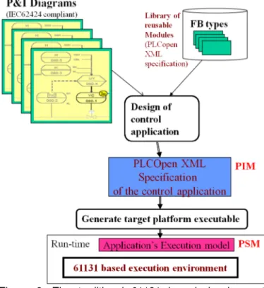
Figure 2 presents the traditional development process of control applications that is based on the IEC 61131 function block model. P&IDs are used as source of requirements for the control application. The control engineer utilizes an IEC 61131 function block tool and using its own experience and knowledge, constructs the design model of the control application. The design is expressed in the form of function block diagrams that are usually stored in PLCopen XML
format. This design specification is what we call platform independent model (PIM) since it is independent of the execution environment on which the control application will be executed. The PIM is next transformed using market tools, e.g., ISaGRAF, to an execution model that is compliant with the target execution environment. This is usually known as platform specific model (PSM). Libraries of reusable components are normally used to increase productivity but also the reliability of the development process and the control application. Libraries include standard libraries, but also domain and project specific ones. Reusable components are in the form of IEC 61131 Function Block types. The whole design process of the control application is based on the skills and experience of the control engineer. A great gap exist between the P&ID specification and the output of the design process that is the PLCopen XML specification of the control application. Forward and backward traceability is not supported and the maintenance of the system is a difficult task that in most of the cases can be performed only by the developer. A manageable and more reliable process is required to address the challenges imposed by the always increasing complexity of today’s industrial automation systems. This is the motivation of the work presented in this paper.
Figure 2. The traditional 61131 based development process.
To increase the productivity and reliability of the traditional development process of control applications, we adopt SysML as specification of the application’s analysis and design models and propose the use of the model driven development paradigm. The use of the MDD paradigm will decrease the gap that exists between P&IDs and the IEC 61131 design models applying a more rigorous and developer independent transformation process. The use of SysML will bring in the development process of industrial control
applications all the widely accepted benefits of this modeling language, but it will also allow the developer to exploit the OO paradigm even though still using traditional development and execution environments.
The activity diagram shown in Figure 3 presents an abstract view of the proposed development process. IEC 61131 compliant P&IDs are used as source of requirements for the process control. PCE requirements captured in P&IDs are expressed using SysML requirement diagrams. This process can be automated using a specific model-to-model transformer, as the CAEX2SysML one shown in figure 3. To reduce the gap between the two representations and facilitate the adoption of SysML requirement diagrams by the control engineer, specific stereotypes are defined as model constructs of the proposed SysML4IEC61131 profile. A commercial SysML case tool that supports the proposed profile will be used to import the so generated requirements diagram. This diagram will provide a bridge between P&IDs and the design models of the control application that will be expressed in SysML notation. These diagrams are next enriched to capture all the other requirements not captured in P&IDs, such as security and safety requirements, and it is refined to be a well defined requirements document. The same SysML tool is used to generate the design specification of the control system, i.e., application and target execution platform. More specifically, SysML diagrams are used to define the structure and behavior of the control application. The use of the SysML4IEC61131 profile should make the SysML diagrams comprehensible for the control engineer. SysML PCE final requirement diagrams can be used to automatically generate SysML early design specs for the control application. These early design specs will be elaborated to get the detailed design specs of the application that will be transformed by the SysML2IEC61131 transformer to design specifications expressed in PLCopen XML format.
Figure 3. The proposed MDD SysML-based development process.
4.
The Meta-model of IEC 61131
For the definition of an MDD process that will result into IEC 61131 compliant design models for the control application the meta-model of the IEC 61131 should be defined. In this section this meta-model is presented and discussed so as to allow its use for the definition of the SysML4IEC61131 profile.
According to the IEC 61131, a Controller is considered as an aggregation of PLCs and Applications. A PLC is considered as an aggregation of CPUs, a Power Unit, I/O Modules and Communication Modules, as shown in Figure 4, which depicts part of the Controller package of the IEC 61131 meta-model. An application is an aggregation of Program Organization Units (POUs), a key class of the POU package. A Controller is associated with one Controlled System that is considered as aggregation of Unit, where each Unit may be of primitive or Composite type. Primitive units are connected to the controlling system through PhysicalI/Os.
Figure 4. The Controller package of the IEC 61131 meta-model (part of).
A Configuration is considered as an aggregation of Resources, Access Paths, Global variables and Type Definitions, as shown in Figure 5, which depicts part of the Configuration package of the IEC 61131 meta-model. The start of a configuration causes the initialization of its global variables and then the start of all its resources. The stop of the configuration’s resources is caused by its stop. A Configuration may span over several PLCs. An access path is an association of a symbolic name with a variable for the purpose of open communication.
Figure 5. The Configuration package of the IEC 61131 meta-model (part of).
Configuration elements are defined according to the standard to support the installation of programmable controller
programs into programmable controller systems. A Resource is associated with one CPU and is considered as aggregation of Global Variables and Task Declarations. The start of a resource causes the initialization of all its variables and enabling all of its tasks. The stop of a resource causes the disabling of all its tasks. A Task Declaration is an aggregation of Task Definitions and ProgramToTask assignments. A task is defined as an execution control element that allows the periodic or triggered execution of a group of associated program organization units.
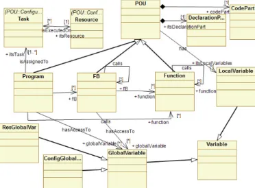
A POU may be of type Program, FB or Function and is defined as an aggregation of a declaration part and a code part, as shown in Figure 6, which depicts part of the POU package of the IEC 61131 meta-model. The same figure also captures the allowed calls between POUs. A Program is assigned to one or more tasks and a task is executed on one Resource, while a resource may execute many tasks. The code part is associated with one SFC, which is not valid for function, or is defined as an aggregation of FBDs or statements (not shown in figure). An FBD is defined as an aggregation of DataConnection, FunctionCall, FBInstanceCall and ExecutionControlElelement.
4.1. The Function Block as an OO construct
Even though not exploited so far, the Function Block concept has introduced in the industrial automation domain basic concepts of the OO paradigm. This facilitates the use of UML and SysML as modeling languages in the context of the proposed MDD process. More specifically, the Function Block construct can be used to capture the structure and behavior of a collection of objects (instances) that may be used in the construction of a control application. Figure 7 presents the interface of a software module, expressed in SFC, for the Feeder unit of the well-known Festo MPS system. Input variables are used to get the sensor values, output variables are used to affect the feeder’s actuators and internal variables are used to store the state of the object.
Figure 6. The POU package of the IEC 61131 meta-model (part of).
The FB icon is a graphical representation, i.e., a view element, of the FB concept and can be considered as a design time construct analogous to the UML class. The textual
construct, which is also used to represent this concept, may be compared with the class construct of OO languages, such as Java and C++. IEC61131-3 allows a mixing of various textual and graphical languages to be used for the program specification. This is not common in software engineering notations. Common programming languages mainly use only a textual representation, while UML or similar graphical notations for modeling, are mainly based on graphical symbols. In general, the Function Block (FB) construct, where the term FB is used for the function block type and the term instance for the FB instance, may be considered as a special kind of class with several restrictions but also extensions. In a similar way to the class, it has a name; it defines the state of its instances using a set of local variables, declared either textually or graphically; and it defines the behavior of its instances through its body. In the remaining of this subsection we discuss the FB construct regarding the definition of its behavior and structure. The OO extension of the FB construct that is under discussion in IEC is not considered in this part.
Figure 7. Interface of an IEC61131 Function Block.
There is a restriction in the behavior definition of the FB; only one method can be defined. However, this method usually captures all the different behaviors exhibited by the FB instances in response to the various messages these instances receive from the environment. This means that there are no method signatures as in common OO languages; actually there is no signature even for this one method defined by the FB body. This method is executed when the FB instance is called. The call of the FB instance depends on the language used, but in all the cases at least the name of the FB instance followed by a list of actual parameters is used. Based on this description of the FB concept, the FB can be considered as a special type of class that defines the behavior of its instances by only one method. The specification of this method can be given either in textual or in graphical notation. A collection of FBNs can be used to graphically specify the behavior. The claim of the standard that “Sequential Function Chart (SFC) elements are defined for structuring the internal organization of programmable controller programs and function blocks” may be understood as defining the SFC for structural representation but this is not correct. The SFC is more convenient in the case that the FB directly implements a state machine, as shown in Figure 8, which presents the SFC behavior specification for the Feeder FB. In this case parallel branches of SFC should not be used even though this restriction is not defined by the standard. If parallel branches of SFC can be used then the 61131 FB construct is a much more powerful construct than the 61499 FB. A comparison of the semantics of SFC with those of the state chart is given in [4]. A textual representation can also be used to specify the behavior of the FB.
Regarding the structure definition there are no formal parameters defined for the method of the FB but instead input and output variables are used for this purpose. So, input and output variables have semantics similar to the method formal parameters, but are defined along with local variables as part of the structure of the FB instances. Input and output variables may be considered analogous to the flow ports defined by SysML, which constitute part of the structure of the classifier. This means that UML aggregation of type composite is supported by FBs. It should be noted that it is not possible to define an FB variable as public, so there is no direct access to the FB state variables from outside of the FB. Output variables may be used to export state information.
Instantiation is not permitted during run time; all the instantiations should take place during the deployment of the part of the application that corresponds to the specific FB diagram. An instantiation is forced on every variable declaration of FB type. This means that only the composite kind of aggregation, i.e., PartAssociation in SysML, is implemented. This kind of association implies that the composite object has responsibility for the existence and storage of the composed objects, i.e., its parts.
Figure 8. Behavior specification of an IEC 61131 FB using SFC [23].
4.2. The Function Block Network as an OO design
time artifact
The FBN is used, according to the standard, to capture the behavior of Programs and FBs. According to this, the closest UML diagrams that can be compared with the FBN are the activity and the collaboration diagrams. However, its execution semantics in terms of execution order and flow of control are quite different from the ones of the above diagrams and also the level of abstraction applied is lower compared to the level of abstraction of the UML diagrams. In activity and the collaboration diagrams of UML the execution order and flow of control may be captured on the diagrams and
explicitly specified by the designer. In FBN there are predefined execution semantics, i.e., the order of calling functions or FB instances, and the designer has to ensure that his design exploits properly the predefined execution semantics to get the desired behavior. The FBN can be considered as analogous to the abstract syntax tree generated by a C compiler to calculate the value of an expression. Like the Activity diagram, the FBN diagram captures the activities that have to be performed and the flow of information between these activities. An FBN that includes only FB instances is more close to a collaboration diagram with the restriction that every object has one method.
Message passing between the nodes of an FBN is not realized in terms of method call that is the common mechanism for message passing in OO languages. In fact, there are no method signatures, but just one FB method which is activated when the FB instance is called. An FB instance can be called by any Program Organization Unit (POU) that has visibility access to it. The FB method is executed on the specific instances structure, i.e., inputs, state and output and the result is normally a new instance state that is captured in the instance’s internal variables (in case of state depended behavior) and a response to the environment that is captured by the instance’s output variables and the value of the FB call. Message passing between FB instances allocated in different resources in the same configuration is implemented by global variables (VAR_GLOBAL) of the configuration, while between those FBs allocated in different configurations it is implemented through access paths defined in configurations with VAR_ACCESS.
It should be noted that the FBN may also be considered as a structural specification diagram like the composite structure diagram of UML 2.0 or the internal block diagram (ibd) of SysML.
A detailed discussion on using IEC 61499, UML and SysML as possible alternatives to work on higher layers of abstraction than the one supported by IEC 61131 is given in [23].
5.
SysML4IEC61131: A SysML ProfileFor IEC
61131
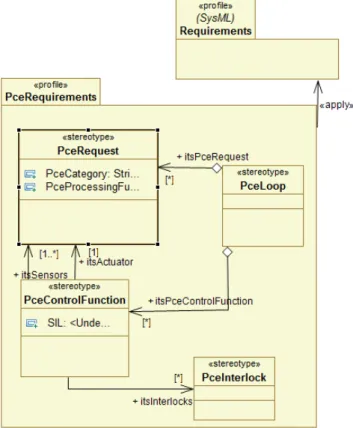
A SysML profile may be defined to facilitate the transition from the traditional approach to the proposed MDA approach. It will be easier for the control engineer to utilize the proposed development process if specific constructs from the IEC61131 domain will be used through the development process. The so called SysML4IEC61131 profile should facilitate the transformation process of the P&ID PCE relevant information to SysML requirements diagram. It will also make this diagram readable to the control engineer. The requirements diagram is the first diagram in the proposed in this paper SysML based IEC 61131 development process. A model transformer is used to extract from the CAEX specification the PCE relevant data and capture them in a
SysML requirements diagram. The stereotype
<<PceRequest>> is defined in order to capture PCE requests in the SysML requirements diagram. The PCE category is defined as an enumeration type. <<PceControlFuntion>> and <<PceLoop>> are other stereotypes related with requirements
specification of this profile, as shown in Figure 9. Elements of type PceControlFuntion can be later mapped to event path elements [24] in the design model of the system. Event paths are used to capture in the design model the event propagation path from a event source to an event sink through a finite number of FBs and event connections. Event paths can be used to capture in the design model the non-functional requirements such as real-time constraints. In [24] deadline and relative priority to other application FBs is assigned. Interlocks, even though can be specified as requirements in P&IDs, are not directly supported by a specific construct of IEC 62424. They can also be defined during design time to obtain a specific functionality or to improve the security level of a specific functionality. The stereotype <<Interlock>> is defined to capture interlocks. The PCE loop may be used as basis for the definition of the architecture of the process control application.
Figure 9. Sample of a PCE Requirements profile capturing PCE basic concepts.
Basic constructs of SysML are adopted in the context of this profile for the engineering of the system, both software and hardware, at high level of abstraction. Based on the requirement diagram the structure and the behavior of the required system should be defined using specific diagrams. The construct of block that is the basic static, structural construct of SysML, is broader than the UML class. The block can be used to represent the modular units of system description. A block can define the “type of logical or conceptual entity, a physical entity, a hardware, software or data component, a person, a facility, an entity that flows in the system or even entities from the environment” [3]. This means that the block construct of SysML may be used to represent not only an FB, but also a function and a configuration. The <<FB>> stereotype will be used to represent the IEC 61131
FB and the <<Function>> stereotype will be used to represent the IEC 61131 function. In a similar way <<Program>> and <<Configuration>> will be defined to represent a program and a configuration respectively. The SysML block definition diagram (bdd) can be used to capture the structure of configurations, programs and also FBs that may accept FB instances as input variables. The SysML internal block diagram (ibd) can be used to capture the interconnections among the constituent parts of constructs, such as configurations, programs and also FBs that may accept FB instances as input variables. The sequence diagram can be used to capture the interactions of the system components in the context of a particular operation of the system. In this way SysML can be used to provide a completely graphical environment for modeling control applications in a higher and also more expressive layer than the one already supported by existing IEC 61131 market tools. The IEC 61131 design diagrams for the application can be automatically created using proper model-to-model transformers that will use as input the corresponding SysML design diagrams. Assuming that a SysML profile for the IEC61131 will be standardized, the proposed approach will result in a uniform way of modeling industrial automation software that will hide the proprietary individual characteristics of IEC 61131 tools at the modeling layer.
For the real-time properties of the system, MARTE [25], a profile for the embedded real-time systems domain, may be used. This profile is complementary to SysML and can be used with SysML to specify this kind of systems at different levels of abstraction [26]. MARTE provides constructs for the modeling of software resources, i.e., the software execution platform, but also for the modeling of the hardware resources, i.e., the hardware execution platform that is for the case of IEC 61131 a network of PLCs. This means that there is a conceptual overlap with SysML, which also provides constructs for the modeling of platforms and their constituent elements, i.e., hardware resources, and the allocation of software to platforms. In these areas, MARTE either reuses the corresponding SysML stereotypes, or defines elements that are conceptually and terminologically aligned with SysML [25]. It should be noted that a similar problem has to be addressed between the SysML2IEC61131 profile and MARTE. In order to avoid conflicts, specific constructs of the MARTE profile will be excluded. An example of such a conflict is the configuration construct. In IEC 61131 the configuration is defined as a language element to declare an entity that contains one or more resources, each of which contains one or more programs executed under the control of zero or more tasks. Configuration in MARTE has a broader meaning. It defines: a) the allocation of the application components to the software application platform components, and b) the allocation of the software application platform components, such as tasks and communication channels to the hardware platform components. The <<allocate>> relationship of UML 2.0 is used for the allocation of higher layer to the layer below. Different system modes may exhibit different configurations.
6.
Conclusion
domain basic concepts of the object-oriented and the model driven development paradigms. However, it fails to support a high level of abstraction specification of the system, while at the same time introduces a great semantic gap between the obtained specification of the system and the process control engineering requirements that are captured on piping and instrumentation diagrams. At the same time, the IEC 61131 paradigm integrates concepts from the procedural programming paradigm with OO ones, making the development process more complicated if the developer decides to exploit the OO paradigm of this standard. SysML appears as a promising modeling notation since it supports higher layers of abstraction in system specification. It also provides an effective handling of requirements and traceability to the design time modeling artifacts, and supports both the procedural and the OO programming paradigms. All these benefits are exploited in the proposed in this paper model driven development process, to increase the effectiveness of the IEC 61131 based development process. PCE requirements captured in CAEX format in IEC 62424 compliant P&IDs are transformed to SysML requirements diagrams. These diagrams are used as input of a SysML based design process that results to a SysML design specification of the system, which is finally automatically transformed to PLCopen XML specification capable to be further handled by market tools. The SysML profile will further facilitate the model driven development process and provide the required infrastructure for the adoption of a mechatronics concurrent engineering process of the different disciplines involved in the development of industrial automation systems.
Acknowledgments
Kleanthis Thramboulidis would like to thank Kari Koskinen and his group at Aalto University for fruitful discussion on IEC 62424 and IEC 61131 in the context of AUKOTON, a TEKES funded project.
References
[1] International Electrotechnical Commission, “IEC International Standard IEC 61131–3: Programmable Controllers, Part 3: Programming Languages”, IEC, 2003.
[2] PLCopen, PLCopen for efficiency in automation, web page: http://www.plcopen.org/
[3] OMG, ”OMG Systems Modeling Language,” V1.0, September 2007.
[4] International Electrotechnical Commission, “IEC International Standard IEC 62424: Representation of process control engineering - Requests in P&I diagrams and data exchange between P&ID tools and PCE-CAE tools”, ed1.0, 12-08-2008. [5] Gerard Berry, “The Esterel v5 Language Primer”, Version v5
91, June 5, 2000.
[6] K. Thramboulidis, “IEC61499 Function Block Model: Facts and Fallacies”, IEEE Industrial Electronics Magazine vol. 3, issue 4, December 2009, pp. 7-26.
[7] CORBA Component Model Specification, v4.0, Available on line: http://www.omg.org/docs/formal/06-04-01.pdf
[8] Thomas A. Henzinger, Christoph M. Kirsch, Marco A.A. Sanvido, and Wolfgang Pree, “From control models to real-time code using Giotto”, IEEE Control Systems Magazine, 23(1):50-64, 2003.
[9] M Winter, et al.; “Components for Embedded Software – The Pecos Approach” 2nd Inter. Workshop on Composition Languages, 16th European Conference on Object-Oriented Programming (ECOOP) Málaga, Spain, June 11, 2002
[10] DECOS web page: https://www.decos.at/
[11] Bohn H., Bobek A., Golatowski, F. “SIRENA - Service Infra-structure for Real-time Embedded Networked Devices: A service oriented framework for different domains”, Inter. Conf. on Networking, (ICN/ICONS/MCL), 23-29 April 2006, pp. 43– 49
[12] Service-oriented ecosystem enables low cost devices to form interactive ‘web of objects’, http://www.itea2.org/eureka_ success_story_soda
[13] J. Wiklander, J. Eliasson, A. Kruglyak, P. Lindgren, J. Nordlander, “Enabling component-based design for embedded real-time software”, JOURNAL OF COMPUTERS, VOL. 4, NO. 12, DECEMBER 2009.
[14] K. Thramboulidis, D. Perdikis, S. Kantas, “Model Driven Development of Distributed Control Applications,” The International Journal of Advanced Manufacturing Technology, Vol. 33, No 3-4, 2007, pp. 233-242.
[15] G. Doukas, K. Thramboulidis, “A Real-Time Linux Based Framework for Model-Driven Engineering in Control and Automation”, IEEE Transactions on Industrial Electronics, Vol. 58, No. 3, March 2011, pp. 914-924.
[16] D.N. Ramos-Hernandez, P.J. Fleming, and J.M. Bass, “A novel object-oriented environment for distributed process control systems,” Control Engineering Practice vol. 13, 2005, pp. 213– 230.
[17] B. Vogel-Heuser, D. Witsch, U. Katzke, “Automatic Code Generation from a UML model to JEC 61131-3 and system configuration tools,” Inter. Conf. on Control and Automation, Budapest, Hungary, June 27-29, 2005, pp. 1034-1039.
[18] K. Sacha, “Verification and Implementation of Dependable Controllers,” 3rd Int. Conf. on Dependability of Computer Systems DepCoS-RELCOMEX, Szklarska Poreba, Poland, June 2008, pp. 143-151.
[19] T. Ritala, S. Kuikka, “UML Automation Profile: Enhancing the Efficiency of Software Development in the Automation Industry”, 5th IEEE Intern. Conf. on Industrial Informatics, July 23-27, Vienna, Austria, 2007.
[20] U. Katzke, and B. Vogel-Heuser, ”Combining UML with IEC 61131-3 languages to preserve the usability of graphical notations in the software development of complex automation systems,” 10th IFAC, IFIP, IFORS, IEA Symposium on Analysis, Design, and Evaluation of Human-Machine Systems, Seoul, Korea, Sept. 2007.
[21] F. Chiron, and K. Kouiss, “Design of IEC 61131-3 function blocks using SysML,” Mediterranean Conf. on Control & Automation (MED '07), Athens Greece, 2007.
[22] R. Drath, A. Fay, T.Schmidberger, “Computer-aided design and implementation of interlocking control code”, IEEE International Symposium on Computer-Aided Control Systems Design (CACSD06), 4-6 Oct. 2006, Munich, pp. 2653 – 2658. [23] K. Thramboulidis, and G. Frey, “Towards a Model-Driven IEC
61131-based Development Process in Industrial Automation,” Journal of Software Engineering and Applications (JSEA), Vol. 4, No. 4, April 2011.
[24] G. Doukas, K. Thramboulidis, “A Real-Time Linux Execution Environment for Function-Block Based Distributed Control Applications”,3nd IEEE International Conference on Industrial Informatics, Perth, Australia, August 2005, (INDIN´05) Page(s): 56-61.
[25] OMG, “A UML Profile for MARTE: Modeling and Analysis of Real-Time Embedded systems”, Beta 2, June 2008.
[26] H. Espinoza, D. Cancila,
B. Selic and S. Gérard, “Challenges in Combining SysML and MARTE for Model-Based Design of Embedded Systems”, Model Driven Architecture - Foundations and Applications, Lecture Notes in Computer Science, 2009, Volume 5562/2009, pp. 98-113.


![Figure 8. Behavior specification of an IEC 61131 FB using SFC [23].](https://thumb-us.123doks.com/thumbv2/123dok_us/9046676.2393310/6.892.64.437.495.860/figure-behavior-specification-iec-fb-using-sfc.webp)