Angular Contact Ball Bearings 40°
TI-I-4044.0 / E
L
Lo
occaattiio
on
n w
wiitth
h T
Trraad
diittiio
on
n
The headquarters in Solms-Oberbiel is centrally located in Germany close to the North/South and East/West highways which also provides for a central location in Europe. The international Airport Frankfurt approx. 80 km away serves as a worldwide link.F
F ll e
ex
xiib
blle
e aan
nd
d R
Re
elliiaab
bll e
e
In the middle of 1996we opened the central computer controlled high shelf warehouse with more than 2.000 pallet places. It is used for finsihed and semi-finished products as well as for large bearings.
This is in addition to our existing two-storage computer controlled service warehouse also with more than 2.500 storage places. Both warehouse systems provide together with our distribution centre and
communication network precise logistics and a worldwide unequaled reliability.
P
P rre
ecciissiio
on
n w
wiitth
h F
Fu
uttu
urre
e .. .. ..
We are future orientated.We have the creativity and vision to perform and provide.
T
Th
hiiss iiss o
ou
urr e
ex
xaacctt p
prre
esse
en
nttaattiio
on
n
tto
o sso
ollu
uttiio
on
nss w
wiitth
h p
prre
ecciissiio
on
n..
Headquarter of the IBC Wälzlager GmbH at the industrial area of Solms-OberbielPrecise Logistics provide an unequaled worldwide reliability
New plant in Asslar
Central Computer Controlled High Shelf Warehouse – Middle 1996
Single Row Angular Contact Ball Bearings of series BE with 40° contact angle
To meet all the different technical applications and operating conditions, accurate solutions are required. Only an extensive range of angular contact ball bearings fulfil the diversity of requirements such as high rotational speed and load carrying capacity, running accuracy, stiffness, as well as combined radial and axial load at low heat generation.
Single Row 40° angular contact ball bearings can accommo-date radial and axial loads in only one direction.
(> See picture 44-101)
Load acting of 40° angular contact ball bearing 44-101
Also external radial loads are creating axial force within the bearing, which has to be compensated by a further bearing. Normally there are two angular contact ball bearings adjusted against each other.
There are typical fields of applications with combined radial and axial load within gears, gear motors, fans, compressors, screw compressors, ventilators, pumps, textile machines, printing machines, conveyors where shaft guidance free of clearance should be achieved.
Distinguishing marks of IBC 40° angular contact ball bearings are quiet running, low friction, high rotational speed and a long lifespan. Especially usage in pumps or compressors are creating combined loads at high rotational speed often under unfavourable lubrication circumstances and heavy contamina-tion.
IBC 40° angular contact ball bearings of BE series, with each one high and one low shoulder at the bearing rings are non-separable. In comparison to series B, load carrying capacity could have been increased due to larger balls.
The larger the axial load carrying capacity the larger the size of contact angle, which is including the conjunction line of both contact points between balls and raceways with the radi-al axis and from which the load is transferred from one race-way to the other.
Dimensions
The main dimensions of the IBC single row angular contact ball bearings are according to DIN 616, ISO 15 and DIN 628, part 1.
Series
IBC angular contact ball bearings are available in various designs. 70BE, 72BE, 73BE (> see picture 44-102). Further variations with other preloads are deliverable on request.
Comparison of cross sections of 40° Angular Contact Ball Bearings 44-102
Materials
Bearing rings and rolling elements are made of bearing steel 100Cr6 (1.3505) corresponding with SAE52100 and SUJ2. Heat treatment
IBC angular contact ball bearings are dimensionally stable and can be used at operating temperatures of up to 130°C. In addition to higher values heat treatment for higher tempera-tures are available on request.
Cages
Depending on bearing design and size, various types of cages are deliverable.
P Solid window cage PA6.6 Polyamide glass fibre reinforced, applicable up to 120 °C
M Solid brass cage
J Steel sheet
K PEEK cage, glass fibre reinforced, applicable up to 200 °C, in case of high rotational speed up to max. 150 °C
Remarks:
If the bearings are lubricated with oil, any additives contained in the oil may reduce the PA6.6 cage service life. At tempera-tures over 120°C steel cages, PEEK or brass cages should be used.
When using in ammonia surroundings such as freezing-appa-ratuses, bearings with brass cages are not suitable.
Sealed versions
IBC supplies types of angular contact ball bearings, which are sealed on both sides. The bearings are filled with lithium soap grease with mineral basic oil.
Bearings with special grease are recognized by suffix. IBC supplies also angular contact ball bearings with shields or seals on one or both sides. Bearings with basic sealing (2RSZ) can be used within a temperature range between –10°C up to +120°C. Sealing with fluor caoutchouc (Viton) is available on request.
Lubricated open bearings
Also open bearings could already be delivered with grease. Lubricants are recognized by suffix.
Hybrid bearings
Bearings with ceramic balls made of silicon nitride Si3N4are applicable for current insulation.
Due to low specific weight of ceramic balls and the resulting low centrifugal forces, an increase in rotational speed of up to 35 % is possible in comparison to steel balls. Thus the dynam-ic load rating is kept and the statdynam-ic load rating is reduced to 70 %.
Coated Bearings (Prefix AC)
ATCoat enables a bearing to be higher resistant against cor-rosion, wear and allows an increase of speed. This is caused by thin dense chromium coat. The special topographic surface also increases the ability of a bearing to withstand emergency situations. All these characteristics lead to use ATCoated IBC bearings under uncomfortable lubrication conditions.
These conditions are for example explained below: – when it is impossible to use a lubricant,
– when it is only possible to use a low viscous lubricant, which cannot create a separating film,
– when movement is not a complete rotation, where the lubri-cant film will not remain,
– when the bearing is unloaded and the rolling elements start to slide,
– when in case of high acceleration or braking the rolling ele-ments start so slide.
The ATCoat bearings are an opportunity to corrosion resistant bearings. The protective coat in connection with ceramic balls provides very good technical features (prefix ACC).
Designs
1) Single bearings
Single bearings are suitable where only one bearing per bear-ing location is used. These sbear-ingle bearbear-ings are positioned in a certain distance to each other.
A specially defined tightening torque via a locknut or a flange makes adjusting of preload or axial clearance. In case of such bearing arrangements single row angular contact ball bear-ings have to be adjusted against each other until the neces-sary preload or axial clearance is reached. The right adjust-ment of both single bearings is quite essential to guarantee the bearing’s functionality. Otherwise lifespan would be reduced caused by higher friction loss and thus resulting higher operating temperatures. Even running noises or move-ment between balls and raceway may occur and thus com-plete load carrying capacity could not be fully used. 2) Universal bearings for mounting in pairs
Single row angular contact ball bearings for universal design are intended for mounting in pairs in T-arrangements (tandem) in such cases when load carrying capacity is not sufficient enough, respectively the bearing arrangements have to carry axial load in both directions (O- or X-arrangement).The uni-versal bearings have a defined ground stick-out S at the lateral faces of the inner and outer ring. This enables adjust-ment without shims.
(> See Picture 44-104 a) with positive and b) with negative clearance, which means preload.)
44-104
Axial clearance and preload classes are given in the table on page 5. The sequence of letters A, B, O, L, M signifies the amount of high axial play to medium preload.
The mentioned figures show the non-mounted bearing arrangements of two bearings without measuring load. Universally ground bearings show the same protruding dis-tance of inner to outer ring on both sides and therefore are applicable for any O-, X- or T-arrangements.
Arrangements
Accommodation of axial load in both directions enables O-and X-arrangement. Due to contact lines meeting in apexes outside of the two bearings, O-arrangement is more suitable for accommodation of tilting moments, considering that ing sets in such arrangements result in a relatively rigid bear-ing arrangement. Comparbear-ing to O-arrangement, the contact lines of X-arrangement are converging within the two bear-ings.
Considering the above, the X-arrangement is less rigid. In case of main load in one direction bearings could be mounted in tandem arrangement. In case of occasional change of load direction a counter acting bearing would be necessary. (Please refer to column “radial clearance and pre-load”.)
Bearing arrangements 44-105
Inclination
Misalignment should be avoided. According to arrangement at max. 2 angular minutes. Inclination is leading to a certain seizure, higher running noise and reduces lifetime.
Whereas X-arrangement is less delicate than O-arrangement.
Clearance and preload
Under appropriate operating conditions and reference speed, very low preload is optional to reach regular and free rolling of elements. Perfect rolling is granted with load distribution Fa/Fr > 1.
That means, in stationary (cold) conditions, bearings are used with minimum internal clearance as under operating condi-tions the inner rings are warming up more than the outer rings and thus clearance is becoming smaller, respectively preload is becoming larger.
Tight fits for shaft and housing are using up further clearance. In case of high operating clearance, load capacity of the bear-ings is not completely used.
In case of unidirectional load in O-and X-arrangement, further considerations should be observed.
The counter bearings should not mainly be discharged tem-porary, as within the discharged bearing unfavourable sliding of balls may happen. This may influence the noise, lubricant film, load on cage and lifespan. Light preload or a clearance free solution should be chosen.
Bearing arrangements with axial clearance and axial preload 44-200
O-arrangement X-arrangement
Tandem-O-arrangement Tandem-arrangement
a) with axial clearance: in O-arrangement
axial preload axial clearance
in X-arrangement
b) with axial preload: in O-arrangement in X-arrangement
axial preload axial clearance
Bore diameter UA UB UO UL UM UH
Series max. min. max. min. max. min. min. max. min. max. min. max.
over incl. [μm] [μm] [μm] [μm] [μm] [μm] 10 – 18 72 31 23 19 11 6 –2 2 –6 –4 –12 –8 –16 73 33 25 21 13 8 –4 4 –8 –6 –14 –10 –18 70 38 30 21 13 4 0 0 –4 –2 –10 –6 –14 18 – 30 72 40 32 23 15 6 –2 2 –6 –4 –12 –8 –16 73 42 34 25 17 8 –4 4 –8 –6 –14 –10 –18 70 47 39 25 17 4 0 0 –4 –2 –10 –6 –14 30 – 50 72 49 41 27 19 6 –2 2 –6 –4 –12 –8 –16 73 51 43 29 21 8 –4 4 –8 –6 –14 –10 –18 50 – 80 72 60 48 34 22 9 –3 3 –9 –6 –18 –12 –24 73 62 50 36 24 11 –5 5 –11 –8 –20 –14 –26 80 – 120 72 67 55 38 26 9 –3 3 –9 –6 –18 –12 –24 73 69 57 40 28 11 –5 5 –11 –8 –20 –14 –26 120 – 180 72 73 61 41 29 9 –3 3 –9 –6 –18 –12 –24 73 75 63 43 31 11 –5 5 –11 –8 –20 –14 –26 180 – 250 72 90 74 51 35 12 –4 4 –12 –8 –24 –16 –32 73 92 76 53 37 14 –6 6 –14 –10 –26 –18 –34 44-201 Axial clearance and preload of IBC 40° angular contact ball bearings (pair arrangements)
Fits for point and circumferential loads
Fits mainly influence the clearance or preload and thus the following information should be observed. First of all it has to be detected which rings accommodate rotating load und which point load. Rings with point load are less critical, as they are only lightly clamped on the counter part. In this way a certain area of the ring diameter is always loaded. The larger the shocks and load are, the stronger the fits should be. Scheme point load und circumferential load (> see picture 40-300).
Point load and circumferential load 40-300
The light fits are used for lighter loads each up to 0.08 · C, the tighter for higher load ratio.
Strong fits and temperature drop between the inner and outer ring result in reduction of radial and axial clearance and has to be considered accordingly.
The fits should be adjusted according to the required preload when operating temperature is reached. For hollow shafts and thin-walled housings stronger fits should be taken.
The factorfor radial clearanceis approximately 0.85 x axial clearance.
Reduction of radial clearance by fits and operating conditions
The radial clearance is approximately reduced by the follow-ing equation:
Sreff= So– (Sint+ ST) [mm] [1.0]
Sreff Effective radial operational clearance
So Clearance before mounting
Sint Reduced clearance due to interference
ST Reduced clearance due to temperature differences
between inner and outer ring
After mounting the following clearance appears:
Sm= So– Sint [1.1]
Sint= Inti· fi+ Into· fo [mm] [1.2]
Inti Interference inner ring
Into Interference outer ring
fi Reduction factor inner ring
fo Reduction factor outer ring
Guidelines:
fi Solid shaft 0.8
fo Steel or cast iron housing 0.7
fi Hollow shaft 0.6
fo Light metal housing 0.5
fiand foare depending on roughness and diameter of bearing rings, respectively the diameter of the hollow shaft. Due to restricted possibility of temperature reduction and small sur-face and frequent over-rolling of bearings elements, there is a temperature difference of 5 – 10 K during operating. When working with cold or hot mediums this value will be changed accordingly.
ST= α ΔTdm [mm] [1.3]
α Expansion value of bearing steel 12 · 10–6/K ΔT Temperature difference inner and outer ring
dm Mean bearing diameter
inner ring stands still
load direction unchanged
Inner ring
Point load
outer ring rotating
load direction unchanged
Outer ring
Circumferential load
outer ring stands still load direction rotating with inner ring
Circumferential load
inner ring rotating load direction rotating with inner ring
Point load
outer ring rotating load direction rotating with outer ring
Point load
inner ring stands still load direction rotating with outer ring
Circumferential load
outer ring stands still
load direction unchanged
Point load
inner ring rotating
load direction unchanged
Circumferential load Weight Weight out-of-balance out-of-balance housing
loose fit transition fit close fit
close fit transition fit
shaft
Precision Inner ring Outer ring Shaft Housing
class PN, P5 P4 PN, P5 P4
P6 P6
Point load on IR IR to be moved OR tight fit g6 g5 g4 M7 M6 M5 circumferential load lightly, slide fit
on AR IR not lightly h6 h5 h4
moveable
Point load on AR IR tight fit OR slight fit j6, js5, js4, H7 H6 H5
circumferential load k6 k5 k4
on IR OR not to be J7 JS6 JS5
moved lightly
Undetermined load OR is relatively J7, JS6, JS5,
tight K7 K6 K5
Tolerances of 40° Angular Contact Ball Bearings
Inner ring [mm] Precision Ø 2,5 10 18 30 50 80 120 150 180 250
to 10 18 30 50 80 120 150 180 250 315
Δdmp Maximum deviation of PN –8 –8 –10 –12 –15 –20 –25 –25 –30 –35
the mean bore diameter P6 –7 –7 –8 –10 –12 –15 –18 –18 –22 –25
from the nominal P5 –5 –5 –6 –8 –9 –10 –13 –13 –15 –18
P4 –4 –4 –5 –6 –7 –8 –10 –11 –12 –15
Kia Radial runout of assembled PN 10 10 13 15 20 25 30 30 40 50
bearing inner ring P6 6 7 8 10 10 13 18 18 20 25
P5 4 4 4 5 5 6 8 8 10 13
P4 2,5 2,5 3 4 4 5 6 6 8 –
Sd Side face runout referring to P5 7 7 8 8 8 9 10 10 11 13
bore of inner ring P4 3 3 4 4 5 5 6 6 7 –
Sia Side face runout of the P5 7 7 8 8 8 9 10 10 13 15
assembled bearing P4 3 3 4 4 5 5 7 7 8 –
inner ring
ΔBs Deviation of single PN, P6 –120 –120 –120 –120 –150 –200 –250 –250 –300 350
inner ring width P5, P4 –40 –80 –100 –120 –150 –200 –250 –250 –300 350
PN, P6, P5, P4 –250 –250 –250 –250 –250 –380 –380 –380 –500 –500
VBs Ring width variation P6 15 20 20 20 25 25 30 30 30 35
P5 5 5 5 5 6 7 8 8 10 13
P4 2.5 2.5 2.5 3 4 4 5 5 6 –
Outer ring [mm] Precision Ø 18 30 50 80 120 150 180 250 315 400 500
to 30 50 80 120 150 180 250 315 400 500 630
ΔDmp Maximum deviation of PN –9 –11 –13 –15 –18 –25 –30 –35 –40 –45 –50
mean outside diameter P6 –8 –9 –11 –13 –15 –18 –20 –25 –28 –33 –38
of nominal P5 –6 –7 –9 –10 –11 –13 –15 –18 –20 –23 –28
P4 –5 –6 –7 –8 –9 –10 –11 –13 –15 –18 –22
Kea Radial runout of assembled PN 15 20 25 35 40 45 50 60 70 80 100
bearing outer ring P6 9 10 13 18 20 23 25 30 35 – –
P5 6 7 8 10 11 13 15 18 20 – –
P4 4 5 5 6 7 8 10 11 13 – –
SD Variation of inclination P5 8 8 8 9 10 10 11 13 13 – –
of outside cylindrical surface P4 4 4 4 5 5 5 7 8 10 – –
to outer ring side face
Sea Side face runout referring to P5 8 8 10 11 13 14 15 18 20 – –
raceway of assembled P4 5 5 5 6 7 8 10 10 13 – –
bearing outer ring
The width tolerances of the outer ring (ΔCs, VCs) are according to those of the inner ring (ΔBs, VBs) Values given in μm
The whole width tolerance of a bearing set is resulting out of the sum of single tolerances.
Tolerances
Additional to normal tolerances PN each series are also avail-able in precision grade P6 and P5. Bearings with precision grade P4 are deliverable on request. P6.UA, P5.UA, P5.UL are standard versions.
Nominal Bore diameter Tolerance of corner width corner width d Radial r1, r3 Axial r2, r4
rmin, r12, r34 over incl. min. max. min. max.
mm mm mm mm 0.2 – – 0.2 0.5 0.2 0.8 0.3 – 40 0.3 0.6 0.3 1.0 40 – 0.3 0.8 0.3 1.0 0.6 – 40 0.6 1.0 0.6 2.0 40 – 0.6 1.3 0.6 2.0 1.0 – 50 1.0 1.5 1.0 3.0 50 – 1.0 1.9 1.0 3.0 1.1 – 120 1.1 2.0 1.1 3.5 120 – 1.1 2.5 1.1 4.0 1.5 – 120 1.5 2.3 1.5 4.0 120 – 1.5 3.0 1.5 5.0 2.0 – 80 2.0 3.0 2.0 4.5 80 220 2.0 3.5 2.0 5.0 2.1 – 280 2.1 4.0 2.1 6.5 2.5 – 100 2.5 3.8 2.5 6.0 100 280 2.5 4.5 2.5 6.0 3.0 – 280 3.0 5.0 3.0 8.0 Circular arc
(external min. nominal corner radii) upon which no material may protrude
Tolerances of adjacent parts for 40° Angular Contact Ball Bearings
Form accuracy of shafts
40-305 40-307
Form accuracy of housings
Feature Tolerance Tolerance Admissible form tolerances symbol value Tolerance/Roughness grade
Bearing tolerance classes
PN P6 P5 P4
Roundness t IT5 IT4 IT3 IT2
2 2 2 2
Cylindrical form t1 IT5 IT4 IT3 IT2
2 2 2 2
Squareness t2 – – – IT3
2
Axial runnout t3 IT5 IT4 IT3 IT3
Concentricity t4 IT6 IT6 IT5 IT4
Roughness Ra
d 80 mm – N6 N5 N4 N4
d 80 mm – N7 N6 N5 N5
Form accuracy of shafts 40-306
ISO main tolerances according to DIN 7151
Diameter Tolerances
Nominal size
More than up to IT0 IT1 IT2 IT3 IT4 IT5 IT6 IT7
mm μm 6 10 0.6 1 1.5 2.5 4 6 9 15 10 18 0.8 1.2 2 3 5 8 11 28 18 30 1 1.5 2.5 4 6 9 13 21 30 50 1 1.5 2.5 4 7 11 16 25 50 80 1.2 2 3 5 8 13 19 30 80 120 1.5 2.5 4 6 10 15 22 35 120 180 2 3.5 5 8 12 18 25 40 180 250 3 4.5 7 10 14 20 29 46 250 315 4 6 8 12 16 23 32 52 315 400 5 7 9 13 18 25 36 57 400 500 6 8 10 15 20 27 40 63
Main tolerances according DIN 7151 40-309
Roughness Raof axial shoulder of spindle, within the housing and of annular spacer: N6 = 0.8 μm Design of adjacent parts
The accuracy of adjacent parts are to be adjusted according to the requirements of application and thereupon the preci-sion of the bearings (> see picture 44-305, picture 44-307). The bearings with their relatively slim rings will adjust them-selves to form deviations of shafts and housings. The chosen fits are depending on the rotational condition of bearing rings in relation to load direction (> see picture 40-300, 40-301, 40-302, page 6).
Feature Tolerance Tolerance Admissible form tolerances, symbol value tolerance/roughness grade
bearing tolerance classes
PN P6 P5 P4
Roundness t IT5 IT4 IT3 IT2
2 2 2 2
Cylindrical form t1 IT5 IT4 IT3 IT2
2 2 2 2
Axial runnout t3 IT5 IT4 IT3 IT3
Concentricity t4 IT7 IT6 IT5 IT4
Roughness Ra
D 80 mm – N6 N6 N5 N5
80 D 250 – N7 N7 N6 N6
D 250 mm – N7 N7 N7 N7
Form accuracy of housings 40-308
Roughness grade Roughness grade Ra
μm N3 0.1 N4 0.2 N5 0.4 N6 0.8 N7 1.6 Roughness grades 40-310
Bearing design
Dimensioning of bearings
According to DIN ISO 281 the nominal lifetime L10is resulting out of the ratio between equivalent dynamical stress P to dynamical load rating C:
(L10means that 90 % of the bearings will attain this lifetime, 10 % may fail)
L10= · 10 6
[h]
60 · n [2.0]
Rotational speed n [min-1]
Equivalent dynamical bearing stress P [N]
When mounting as single bearing or two single bearings in T-arrangement (tandem):
P = Fr if Fa/Fr<1.14 [2.1]
P = 0.35 Fr+ 0.57 Fa if Fa/Fr>1.14 [2.2]
Dynamical load capacity C of two single bearings in T-arrangement (tandem) is: Csingle bearingx 1.62. Determining of axial load accommodated by single bearings in T-arrangement (tandem)
Radial forces are producing an axial component; axial load has to be determined according to the already mentioned life-time calculation (> see picture 44-400). (These equations are only valid under operating conditions without any clearance or preload.)
The reduction factor R is considering the contact conditions according to load condition Ta/C that means the external axial load and the dynamic capacity (without external load Tais R = 1).
Reduction factor R for Ta
44-401
Bearing arrangements in O- or X-arrangement:
P = Fr + 0.55 Fa if Fa/Fr< 1.14 [2.3]
P = 0.57 Fr+ 0.93 Fa if Fa/Fr> 1.14 [2.4]
(Faand Fraffect the bearing pair)
Extended lifetime calculation Lna
In the so called extended lifetime calculation Lnadepends on a variety of influences and safety requirements e. g. the modified materials, lubrication conditions, the cleanliness etc. in the modified lubricating gap the lubricant additives and the bearing type.
Lna= a1a2a3L10[h] [2.5]
a1 life adjustment factor
a2 factor for material a2 = a2b· a2s· a2w [2.6]
a3 factor for operating conditions
Bearing arrangement Load condition Axial force FaA Axial force FaB
case A1 case A2 case A3 case B1 case B2 case B3 X-arrangement O-arrangement X-arrangement O-arrangement
Axial forces with two angular contact ball bearings in X-, O- or in T-arrangement 44-400
冉
C冊
3Reliability factor a1 Reliability factor % Lna a1 90 L10a 1 95 L5a 0.62 96 L4a 0.53 97 L3a 0.44 98 L2a 0.33 99 L1a 0.21
Life adjustment factors of material a2
When using high quality bearing steel like 100Cr6 (1.3505) lifetime factor a2permits value 1. Surface treatment, heat sta-bilisation of steel, the use of ceramic balls (silicon nitride) may change the life adjustment factor a2.
Extension by single factors a2b, a2sand a2wis therefore rec-ommendable.
a2= a2ba2sa2w [2.6]
Material factor a2
Ring heat rolling element
material a2b stabilisation a2s material a2w
100Cr6 1 150 °C 1 100Cr6 1
Uncoated 1 200 °C 0.75 Si3N4
-IR ATCoat 1.25 250 °C 0.45 balls 2
AR ATCoat 1.2
IR + AR ATCoat 1.5
Life adjustment factor a3
The attainable life depends on a variety of influences e.g. operating conditions, correct lubrication considering rotational speed and temperature, cleanliness in the lubrication gap or foreign particles.
Operating factor a3, is consisting of steel temperature factor a3ts(so far it has not yet been calculated together with heat factor a2S, then a3ts= 1 up to 150°C) and the factor a3vi, which is considering the operating temperature and the contamina-tion.
a3= a3ts· a3vi [2.7]
a3ts steel temperature factor (up to 150°C = 1)
a3vi viscosity factor
Further on lifetime of grease should be checked with bearing lifetime.
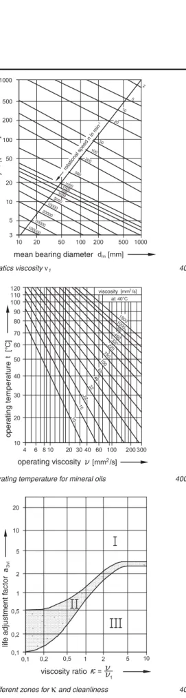
Calculation of life adjustment factor a3viin picture 40-503
via viscosity ratio
κ
First of all the rated viscosity ν1has to be determined, which is depending on rotational speed and the medium bearing diameter, see diagram picture 40-501, and the real viscosity ν at operating temperature, see diagram picture 40-502. These factors have to be put in a ratio to result in
κ
-value.κ
= ν/ν1.Required kinematics viscosity ν1 40-501
Viscosity at operating temperature for mineral oils 400-502
Diagram with different zones for κ and cleanliness 40-503
When using lubricants with a density that deviates from
ϕ.. = 0.9 g/cm3(mineral oil)
κ
has to be corrected by multi-plying ϕ/0.9 g/cm3with the density ratio (especially in case of high temperature grease).Life adjustment factor
rated viscosity
mean bearing diameter
rotational s peed n in mi n -1 oper ating temper ature operating viscosity viscosity at lif e adjustment f actor viscosity ratio
The ratio
κ
is required for locating the life adjustment factor a3vivia spread zones in diagram 40-503. The spread curve II is showing normal operating conditions and normal cleanli-ness of lubricant. Higher value within the spread zone of curve could be reached by using adequate additives within the rangeκ
<1. If adequate quantities of an appropriate grease are used within the rangeκ
<1 higher values can be reached within the spreading of the curve. Special additives such as solid additives, polar property improves, and poly-mers reduce wear corrosion and enhance adhesion of lubri-cants in lubrication gap.Low stress and high cleanliness together with suitable addi-tives permit
κ
-values > 1 and even a3vi-factors within range I. a3-values < 1 should be applied when viscosity of lubricants on mineral oil basis at operating temperatures of ball bearings equates < 13 mm2/s and when the rotational speed value n dm<10 000 mm/min thereupon is relatively small. Cleanliness factor of lubrication gap regarding size of a3vivalueIn ratio with the bearing size, only particles with a hardness > 50 HRC have to be taken into account. The necessary oil cleanliness class ISO 4406 is an objectively measurable level of the contamination of a lubricant and ISO 4572 defines the filtration ratio, for example filtration ratio β6 >75 means that only one of 75 particles passes through the filter. There are 5 oil cleanliness grades with corresponding filtration ratio. It should be observed that filters larger than β25 >75 are not applicable due to general life expectancy. In case of special requirements regarding accuracy of precision spindles a dust particle of 5 μm and hardness of > 50 HRC is far too much for such special applications. In that case work should be done under highest purity aspects.
For possible a3vi-values see picture 40-503:
> 1 utmost conditions: no particles, highest oil clean-liness grade
0.8 high cleanliness of bearings with shield and sealing, medium oil restrain values
0.1–0.5 open bearings with standard grease, where contami-nation by oil and humidity may penetrate into the bearing or non-filtered oil is used.
Lubricant service life
High operating temperatures over 70°C, due to self-heating or caused by high external temperatures may affect the lubricant lifetime and thereupon the whole bearing lifetime. Bearing life-time and lubricant lifelife-time should be compared. See diagram picture 40-504, 40-505, 40-506.
Attainable lubricant lifetime according to diagram picture 40-506 is reduced together with the lubricant temperature value a3faccording to picture 40-504. Further lubricant lifetime factors are resulting in those factors mentioned on page 12 [2.14] and further on by air flow through the bearing of 0.1 – 0.7. In comparison with Lnabearingand Lhgreasere-lubrication is appropriate.
This is depending on the distance between lubricant operat-ing temperature (bearoperat-ing temperature at the inner roperat-ing tb) to the max. allowed grease temperature limit tlimit.
Reduction of grease lifetime may happen from 70°C; at= 1 i.e. when using lithium soap based grease on mineral oil base; with synthetic oils, considerable differences are possible.
In case of lasting stress at temperatures permitted only for short terms at= 2, grease lifetime will be reduced considerably.
Grease life time 40-504
Grease service life at certain temperatures 40-505
Lubrication intervals 40-506
Grease temper
ature v
alue
limit
Only valid for grease with high operating temperatures
Only valid for grease with low operating temperatures
Lithium soap based grease Li Oper ating temper ature Operating time Lubr ication inter v al t g rease
Equivalent static bearing load Po
For single bearings and tandem bearings:
Po= 0.5 Fr+ 0.26 Fa [2.8]
(Po< Frcalculated with Po= Fr)
For bearing pairs in O- and X-arrangement:
Po= Fr+ 0.52 Fa [2.9]
Static load ratings for two matched bearings:
Co= 2 Co single bearing [2.10]
Static safety factor: s0= C0/P0 [2.11]
The requirements are depending on the requested quiet run-ning and shock load.
Usual values for s0: 0.5 ...2
Reference rotational speed nr
Load and lubrication conditions are defined in ISO 15312. The reference speed for oil and grease are mentioned therein referring to a steady state temperature of 70°C.
At a constant 5% radial load of static load rating CO, at an ambient temperature of 20°C is taken as a basis for oil lubri-cation with mineral oil without EP additives, kinematic viscosi-ty 12 mm2/s (ISO VG 32) with oil level reaching up to 30 % of the bottom rolling element or grease lubrication with lithium soap and mineral base oil of 100–200 mm2/sec (ISO VG 150) at a temperature of 40°C with a filling grade of 30 % free space within the bearing.
When using grease a reference temperature of 70°C can be reached after 20 h of grease distribution.
For bearings with rotating outer ring these values may be reduced under certain circumstances. Reference speed val-ues are no speed limits. These figures only state that a tem-perature level of 70°C can be reached for single bearings under the above-mentioned load and lubrication conditions. For duplex bearings the rotational speed is reduced by 20 % for normal internal bearing clearance. Compared with polyamide cages the rotational speed for steel and brass cages are reduced by 6 %.
If no reference speed could be determined such as for sealed bearings, the limiting speed values of rubbing seals are indicated.
Depending on load ratio C/P the following speed characteris-tic values are suitable:
C/P Speed ratio dmx n [mm/min]
15 500 000
8 400 000
4 300 000
Determination of permissible operating speed nperm
depending on load and oil viscosity
As reference speed nris only defined for a special percentage load ratio under certain lubrication conditions, the admissible operational speed npermfor other load and lubrication conditions has to be determined with the corresponding coefficients.
For reference values for load depending value fpand viscosity factor fvfor oil lubrication please refer to diagram picture 44-507.
nperm= fpfvnr [2.12]
In case of grease lubrication two values are obtained for fv and put into proportion to each other.
nperm=
fpfv basic oil actual
nr [2.13]
Further reduction factors: [2.14]
Vertical shaft: 0.8
Rotating outer ring: 0.6
Shock load, vibrations: 0.4 ... 0.9
Rotational speed higher than reference speed
Due to heat dissipation by oil lubrication, air or liquid cooling of inner and outer rings, higher rotational speed can be obtained.
Correction factors for fpand fv picture 44-507 fv basic oil ISO VG 150
Minimum load
Especially in case of high-speed bearings a minimum load should be designated to avoid sliding of rolling elements. Should the weight of the supported parts not be sufficient, corresponding loads could be applied by spring preloading. For single bearings and tandem arrangements a minimum axial load Fa minand for bearing arrangements in O- and X-arrangement a minimum radial load Fr minshould be applied.
Fa min= kaCodm2n210–13 [2.14]
Fr min= kr(n ν) dm210–6 [2.15]
Fa min minimum axial load [N]
Fr min minimum radial load [N]
ka minimum axial load factor for
series 72 = 1.4; series 73 = 1.6
kr minimal radial load factor for
series 72 = 95; series 73 = 100 Co static load [N]
ν base oil viscosity at operating temperature [mm2/s]
n speed [min-1]
dm mean bearing diameter [mm]
In case of high speed it has to be taken into consideration that higher speed means that because of centrifugal forces the balls of single spring preloaded bearingsat the outer ring will be pressed to the centre of the raceway and those at the inner ring will be pressed up to the bord.
To keep the contact angle of 40° of spring preloaded single bearings constant at the inner and outer ring, the following minimum spring preload has to be applied:
Fspring= 25 Co2nmax210–15[N] [2.16]
open
O-arrangement X-arrangement Tandem-arrangement
Open, sealed 40° angular contact ball bearings as single and matched bearing sets
Designation system 40° Angular Contact Ball Bearings
2 3 CB 70 05 . BE P . P6 .DBA 72 06 . BE K . P5 . UL 73 05 . BE P .2RSZ . P5 . UO 72 05 . BE J . UA 73 07 . BE M . P6 . UA ACC- 73 08 . BE M . P5 . UO . A15.GH62 Material – Steel balls 100 Cr6 CB Ceramic balls Si3N4
AC- Rings ATCoated
ACC- Rings ATCoated + balls Si3N4
Lubrication
– Corrosion protected G.. BearLub grease
Coating with ATCoat
A11 Inner and outer ring ATCoated A15 Inner and outer ring ATCoated, rolling
elements and cage corrosion protected* A 21 Inner ring ATCoated
A 31 Outer ring ATCoated
Axial clearance / preload, universal bearing
UA Axial clearance UB Small axial clearance UL Light preload UO Without play A..-.. Axial clearance range Bearing arrangement DB, DF, DT Series 70.. 72.. 73.. Design C BE 40° contact angle
reinforced inner construction
Cage
P Window cage PA 6.6 glass fibre reinforced M Solid machined brass
J Steel sheet
K Window cage PEEK glass fibre reinforced
Precision classes
P6 Dimensional and running accuracy acc. to ISO class 6 P5 Dimensional and running accuracy acc. to ISO class 5 P4 Dimensional and running accuracy acc. to ISO class 4
Sealing
RSZ Friction reduced sealing at one side 2RSZ Friction reduced sealing at both sides ARSZ At one side – IR lower bord
BRSZ At one side – IR high bord
Designation system 44-900
Bore code
00 10 mm 02 15 mm
01 12 mm 03 17 mm
At number 04 and upward x 5 [mm]
44-106
*Corrosion protection depending on application, for further information please refer to main catalogue
Primary dimensions Basic designation Basic load ratings Fatigue load Reference speed Weight
dyn. stat. limit
d D B C Co Pu(radial) nr mm N N min–1 kg 10 30 9 7200.BE 7 700 3 700 140 30 200 0.030 12 32 10 7201.BE 8 300 4 100 160 28 000 0.036 12 37 12 7301.BE 12 900 6 500 210 25 900 0.060 15 35 11 7202.BE 9 600 5 100 205 25 900 0.045 15 42 13 7302.BE 16 600 9 600 280 21 600 0.083 17 40 12 7203.BE 11 800 6 500 250 21 600 0.065 17 47 14 7303.BE 19 000 10 900 360 19 400 0.110 20 47 14 7204.BE 15 700 8 900 360 18 300 0.110 20 52 15 7304.BE 22 200 13 600 430 16 200 0.140 25 47 12 7005.BE 14 800 9 300 385 18 900 0.074 25 52 15 7205.BE 17 400 10 900 430 16 200 0.130 25 62 17 7305.BE 30 900 19 500 660 14 000 0.230 30 55 13 7006.BE 20 600 13 000 520 15 600 0.110 30 62 16 7206.BE 24 200 15 600 660 12 900 0.200 30 72 19 7306.BE 37 700 25 200 900 11 800 0.340 35 62 14 7007.BE 27 100 17 500 700 14 200 0.150 35 72 17 7207.BE 31 900 21 200 880 11 800 0.280 35 80 21 7307.BE 46 000 31 900 1 150 10 800 0.450 40 68 15 7008.BE 32 100 22 000 880 12 400 0.180 40 80 18 7208.BE 37 800 26 600 1 100 10 200 0.370 40 90 23 7308.BE 57 800 40 500 1 350 9 700 0.630 45 75 16 7009.BE 35 700 24 500 980 11 300 0.230 45 85 19 7209.BE 42 000 29 800 1 250 9 700 0.420 45 100 25 7309.BE 69 600 50 400 1 750 8 600 0.850 50 80 16 7010.BE 37 000 27 500 1 100 10 200 0.250 50 90 20 7210.BE 43 500 33 000 1 350 8 600 0.470 50 110 27 7310.BE 81 500 55 500 2 200 7 500 1.100 55 100 21 7211.BE 55 000 41 500 1 650 8 100 0.620 55 120 29 7311.BE 91 000 71 000 2 550 7 000 1.400 60 110 22 7212.BE 66 000 51 000 2 150 7 300 0.800 60 130 31 7312.BE 104 000 82 500 3 200 6 400 1.750
– Bearings with brass cage M have 5% less capacity due to inner construction. – Static capacity Coof hybride bearings CB = 0.7 Coof bearings with steel balls.
Basic Dimensions Abutment and fillet dimensions designation
a d1 D1 r12min r34min damin Damax Dbmax ramax rbmax
mm mm 7200.BE 13 18.2 23.1 0.6 0.3 15.0 25.0 27.0 0.6 0.3 7201.BE 14 20.2 25.1 0.6 0.3 16.2 27.8 29.0 0.6 0.3 7301.BE 16 21.8 28.3 1.0 0.6 17.6 31.4 32.8 1.0 0.6 7202.BE 16 22.2 28.0 0.6 0.3 19.2 30.0 32.0 0.6 0.3 7302.BE 18 26.0 32.6 1.0 0.6 20.6 36.4 37.8 1.0 0.6 7203.BE 18 25.9 31.9 0.6 0.6 21.2 35.0 35.0 0.6 0.3 7303.BE 20 28.7 36.2 1.0 1.0 22.6 41.4 42.0 1.0 0.6 7204.BE 21 30.7 37.2 1.0 0.6 26.0 41.0 42.4 1.0 0.6 7304.BE 23 32.9 41.0 1.1 1.0 27.0 45.0 47.8 1.0 0.6 7005.BE 21.5 31.4 40.4 0.6 0.3 30.0 42.0 45.0 0.6 0.3 7205.BE 24 35.7 42.2 1.0 0.6 31.0 46.0 48.2 1.0 0.6 7305.BE 27 39.4 48.9 1.1 1.0 32.0 55.0 57.8 1.0 0.6 7006.BE 25 37.2 46.9 0.6 0.3 36.0 49.0 53.0 0.6 0.3 7206.BE 27 42.3 50.8 1.1 0.6 36.0 56.0 57.4 1.0 0.6 7306.BE 31 46.2 57.3 1.1 1.0 37.0 65.0 67.8 1.0 0.6 7007.BE 29 43.4 53.3 0.6 0.3 41.0 56.0 60.0 0.6 0.3 7207.BE 31 49.3 59.0 1.1 0.6 42.0 65.0 67.8 1.0 0.6 7307.BE 35 52.4 64.2 1.5 1.0 44.0 71.0 74.4 1.5 1.0 7008.BE 32 49.2 58.8 0.6 0.3 46.0 62.0 66.0 0.6 0.3 7208.BE 34 55.9 66.3 1.1 0.6 47.0 73.0 75.8 1.0 0.6 7308.BE 39 59.4 72.4 1.5 1.0 49.0 81.0 84.4 1.5 1.0 7009.BE 35 53.2 65.3 0.6 0.3 51.0 69.0 73.0 0.6 0.3 7209.BE 37 60.5 70.9 1.1 0.6 52.0 78.0 80.8 1.0 0.6 7309.BE 43 66.3 80.7 1.5 1.0 54.0 91.0 94.4 1.5 1.0 7010.BE 38 57.6 70.3 1.0 0.6 56.0 74.0 78.0 0.6 0.3 7210.BE 39 65.5 75.9 1.5 1.0 57.0 83.0 85.8 1.0 0.6 7310.BE 47 73.5 89.7 2.0 1.0 60.0 100.0 104.0 1.5 1.0 7211.BE 43 72.4 84.1 1.5 1.0 64.0 91.0 94.0 1.5 1.0 7311.BE 51 80.0 97.6 2.0 1.0 65.0 110.0 114.0 2.0 1.0 7212.BE 47 79.3 92.5 1.5 1.0 69.0 101.0 104.0 1.5 1.0 7312.BE 55 87.0 106.0 2.1 1.1 72.0 118.0 123.0 2.0 1.0
Primary dimensions Basic designation Basic load ratings Fatigue load Reference speed Weight
dyn. stat. limit
d D B C Co Pu(radial) nr mm N N min–1 kg 65 120 23 7213.BE 74 000 60 500 2 300 6 400 1.000 65 140 33 7313.BE 121 000 89 500 3 650 5 900 2.150 70 125 24 7214.BE 80 000 67 500 2 550 5 900 1.100 70 150 35 7314.BE 133 500 101 000 3 900 5 400 2.650 75 130 25 7215.BE 82 000 72 000 2 650 5 900 1.200 75 160 37 7315.BE 149 000 119 000 4 150 5 400 3.200 80 140 26 7216.BE 92 000 80 000 2 800 5 600 1.400 80 170 39 7316.BE 161 000 131 000 4 500 4 800 3.700 85 150 28 7217.BE 103 500 92 000 3 300 5 100 1.800 85 180 41 7317.BE 172 500 146 000 4 900 4 800 4.300 90 160 30 7218.BE 122 000 107 000 3 700 4 800 2.200 90 190 43 7318.BE 184 000 161 000 5 300 4 300 5.000 95 170 32 7219.BE 133 500 115 000 4 400 4 600 2.600 100 180 34 7220.BE 148 500 131 000 4 400 4 300 3.200 100 215 47 7320.BE 222 000 207 000 7 000 3 700 7.200 105 190 36 7221.BE 164 500 148 000 4 800 4 100 4.200 110 200 38 7222.BE 176 000 164 500 4 900 3 700 4.500 110 240 50 7322.BE 257 500 257 500 7 200 3 400 9.300 120 215 40 7224.BE 191 000 184 000 5 300 3 400 5.300 120 260 55 7324.BE 287 500 299 000 7 700 2 700 12.400 130 230 40 7226.BE 214 000 218 500 6 100 3 200 6.200 130 280 58 7326.BE 316 000 345 000 9 000 2 700 15.200 140 250 42 7228.BE 225 500 244 000 6 500 2 700 8.600 140 300 62 7328.BE 345 000 391 000 10 000 2 400 20.500 150 270 45 7230.BE 257 500 293 000 7 000 2 400 11.000 150 320 65 7330.BE 373 500 448 500 10 500 2 200 25.000 160 290 48 7232.BE 292 000 322 000 8 500 2 300 13.500 170 310 52 7234.BE 334 000 354 000 9 300 2 100 16.000
– Bearings with brass cage M have 5% less capacity due to inner construction. – Static capacity Coof hybrid bearings CB = 0.7 Coof bearings with steel balls.
Basic Dimensions Abutment and fillet dimensions designation
a d1 D1 r12min r34min damin Damax Dbmax ramax rbmax
mm mm 7213.BE 50 86.3 101.0 1.5 1.0 74.0 111.0 114.0 1.5 1.0 7313.BE 60 93.8 114.0 2.1 1.1 77.0 128.0 133.0 2.0 1.0 7214.BE 53 91.3 106.0 1.5 1.0 79.0 116.0 119.0 1.5 1.0 7314.BE 64 100.0 123.0 2.1 1.1 82.0 138.0 143.0 2.0 1.0 7215.BE 56 96.5 111.0 1.5 1.0 84.0 121.0 124.0 1.5 1.0 7315.BE 68 108.0 130.0 2.1 1.1 87.0 148.0 153.0 2.0 1.0 7216.BE 59 104.0 118.0 2.0 1.0 91.0 129.0 134.0 2.0 1.0 7316.BE 72 115.0 137.0 2.1 1.1 92.0 158.0 163.0 2.0 1.0 7217.BE 63 110.0 127.0 2.0 1.0 96.0 139.0 144.0 2.0 1.0 7317.BE 76 122.0 145.0 3.0 1.1 99.0 166.0 173.0 2.5 1.0 7218.BE 67 117.0 135.0 2.0 1.0 101.0 149.0 154.0 2.0 1.0 7318.BE 80 129.0 153.0 3.0 1.1 104.0 176.0 183.0 2.5 1.0 7219.BE 72 124.0 143.0 2.1 1.1 107.0 158.0 163.0 2.0 1.0 7220.BE 76 131.0 151.0 2.1 1.1 112.0 168.0 173.0 2.0 1.0 7320.BE 90 145.0 173.0 3.0 1.1 114.0 201.0 208.0 2.5 1.0 7221.BE 80 138.0 159.0 2.1 1.1 117.0 178.0 183.0 2.0 1.0 7222.BE 84 145.0 167.0 2.1 1.1 122.0 188.0 193.0 2.0 1.0 7322.BE 98 161.0 194.0 3.0 1.1 124.0 226.0 233.0 2.5 1.0 7224.BE 90 157.0 179.0 2.1 1.1 132.0 203.0 208.0 2.0 1.0 7324.BE 107 178.0 211.0 3.0 1.1 134.0 246.0 253.0 2.5 1.0 7226.BE 96 169.0 193.0 3.0 1.1 144.0 216.0 222.0 2.5 1.0 7326.BE 115 190.0 228.0 4.0 1.5 147.0 263.0 271.0 3.0 1.5 7228.BE 103 183.0 210.0 3.0 1.1 154.0 236.0 243.0 2.5 1.0 7328.BE 123 203.0 243.0 4.0 1.5 157.0 283.0 291.0 3.0 1.5 7230.BE 111 197.0 226.0 3.0 1.1 164.0 256.0 263.0 2.5 1.0 7330.BE 131 216.0 259.0 4.0 1.5 167.0 303.0 311.0 3.0 1.5 7232.BE 118 211.0 242.0 3.0 1.1 174.0 276.0 283.0 2.5 1.0 7234.BE 126 226.0 260.0 3.0 1.1 185.0 297.0 304.0 2.5 1.0
1. Two bearings 7207.BEP.P5.UL with two spacers of same size are used for a cutting knife support. Easy mounting is possible without any further adjustments due to ground preload. Grease lubrication rotational speed is 7000 min–1. The whole set has been completely mounted and supplied by IBC, including shaft and housing. (See picture 44-801, 44-801a)
2. Bearings in O-arrangement have been built in at a belt driven pump support. The O-arrange-ment better bears the moO-arrange-ment of tensile load of the V-belt. (> See picture 44-802)
(For further components like precision locknuts and labyrinth seals refer to catalogue TI-1-5000.0/E, TI-I-5010.2/E or TI-I-5020.0/E.)
3. In case the pump shaft is driven directly by a motor axially mounted with an intermediate coupling, X-arrangement should be preferred for better compensation of alignment faults. (> See picture 44-803)
More of IBC . . .
Company Profile
(German) (English) Lieferprogramm Hochgenauigkeits-Wälzlager Präzisionslagereinheiten · Präzisionsspannmuttern TI-I-5000.0 / DProduct Range
Super Precision Bearings
T1-I-5000.0 / D (German) T1-I-5000.0 / E (English)Product Range
Price List
Super Precision Bearings
TI-I-5003.2 / E
Super Precision Bearings
Service Catalog
T1-1-5003.1 / D (German) T1-1-5003.2 / E (English)
Linear Motion Bearings
T1-1-7001.2 / D (German) T1-1-7001.1 / E (English) IBC Wälzlager mit ATCoat Beschichtung TI-1-5010.2/DATCoated Bearings
TI-1-5010.2 / D (German)© Copyright 2006 IBC Wälzlager GmbH Wälzlager für Kugelgewindetriebe
Axial-Schrägkugellager 60° Präzisionslagereinheiten · Präzisionsspannmuttern
TI-I-5010.2 / D
Ball Screw Support Bearings
TI-I-5010.2 / D (German) TI-I-5010.2 / E (English) Präzisions-Spannmuttern Labyrinth-Spannmuttern Labyrinth-Dichtungen TI-I-5020.0 / DPrecision Locknuts
T1-I-5020.0 / D (Deutsch) T1-I-5020.0 / E (English)Telescopic Rails
T1-1-7005.1 / D (German)IBC WÄLZLAGER GMBH
INDUSTRIAL BEARINGS AND COMPONENTS
Post box 1825 · 35528 WETZLAR (GERMANY)
Tel: +49/64 41/95 53-02 Corporate office Fax: +49/64 41/5 30 15 Industriegebiet Oberbiel
D-35606 Solms-Oberbiel
e-mail: [email protected] http://www.ibc-waelzlager.com
IBC INDUSTRIAL BEARINGS
AND COMPONENTS AG
Tel: +41/32/6 52 83 53 Corporate office Fax: +41/32/6 52 83 58 Kapellstrasse 26