www.EMC.com
EMC Unified Corporate Systems Engineering Corporate Headquarters Hopkinton, MA 01748-9103 1-508-435-1000 www.EMC.com Revised: 6/23/2011 4:57 PM
Applied Best Practices
P/N PART NUMBER A
EMC Unified Storage Best Practices for Performance and Availability
Copyright © 2011 EMC Corporation. All rights reserved. Published June, 2011
EMC believes the information in this publication is accurate of its publication date. The information is subject to change without notice.
The information in this publication is provided “as is”. EMC Corporation makes no representations or warranties of any kind with respect to the information in this publication, and specifically disclaims implied warranties of merchantability or fitness for a particular purpose.
Use, copying, and distribution of any EMC software described in this publication requires an applicable software license.
For the most up-to-date listing of EMC product names, see EMC Corporation Trademarks on EMC.com. EMC2, EMC, the EMC logo, and where information lives are registered trademarks or trademarks of EMC Corporation in the United States and other countries. All other trademarks used herein are the property of their respective owners.
EMC Unified Storage Best Practices for Performance and Availability— Common Platform and Block Storage 31.0 -- Applied Best Practices
Contents
About this Document ... 5
Using Best Practices ... 7
How to Use Best Practices ... 7
File Environment Best Practices ... 7
Legacy Storage System Best Practices ... 7
Storage System Fundamentals ... 8
Terminology... 8
Common Best Practices ... 8
Chapter 1 Host Best Practices ... 11
Performance ... 11
Application tuning ... 11
Different I/O types ... 11
Application buffering, and concurrency ... 14
Volume managers... 14
Host HBAs ... 14
Host file systems ... 14
Availability... 21
PowerPath ... 21
Other multipath I/O services (MPIO)... 21
ALUA (Asymmetric Logical Unit Access) ... 22
Storage network attachment ... 24
Chapter 2 Network Best Practices ... 27
Performance ... 27
iSCSI protocol ... 27
Availability... 30
Fibre Channel ... 30
FCoE protocol ... 30
iSCSI protocol ... 30
Chapter 3 Storage System Platform Best Practices ... 32
Performance ... 32
Front-end ports ... 32
Storage processors ... 34
Mirrored Cache ... 35
Back-end ... 39
FAST Cache ... 44
Physical Storage ... 49
Availability... 55
Back-end ... 55
Chapter 4 Block Storage System Best Practices ... 66
Performance ... 66
RAID groups ... 66
RAID group creation ... 71
4
Pool capacity estimate ... 93
Availability ... 101
RAID groups ... 101
Basic LUN Availability ... 101
Pool Availability ... 102
Chapter 5 Storage System Sizing and Performance Planning ... 104
Introduction ... 104
Workload ... 104
The Capacity ... 104
Performance ... 105
Performance estimate procedure ... 107
Sizing example: homogenous pool... 110
Step 1: Determine the workload ... 110
Step 2: Determine the I/O drive load ... 111
Step 3: Determine the number of drives required for Performance ... 111
Step 4: Determine the pool capacity ... 112
Step 5: Determine the number and type of storage systems ... 113
Step 6: Analysis ... 114
Sizing example: FAST VP pool ... 114
Considering Locality ... 114
Step 1: Determine the workload ... 114
Step 2: Determine the required tier Capacity of the top tier... 115
Step 3: Determine the required tier I/O drive load of the top tier ... 116
Step 5: Analysis ... 117
Sizing example: FAST VP pool with FAST Cache ... 118
The Hit Rate ... 118
Step 1: Determine the workload ... 119
Step 2: Determine the required tier Capacity of the top tier... 119
Step 3: Determine the required tier I/O drive load of the top tier ... 120
Step 5: Analysis ... 121
Pool sizing summary and conclusion ... 122
Conclusion ... 123
Glossary of Terms ... 124
About this Document
This document provides an overview of the performance and availability Best Practices for the EMC VNX-series. It was developed by the EMC Corporate Systems Engineering group. Purpose
Information in this document can be used as the basis for general best practices for performance and availability of the VNX platform for both block and file storage.
Audience
This document is intended for VNX storage system administrators, EMC field and sales
personnel, partners, and new customers. EMC service and sales organization may use parts of this document in sales kits and other technical documentation.
Scope
This document examines best practices for achieving best performance and availability with EMC® VNX™ series storage systems. It discusses factors influencing VNX-series availability
and performance at the host, network, and storage system level using the VNX Block Operating Environment 31.0 (VNX OE Block 31.0). Specific VNX models addressed include:
VNX5100 (Block storage only) VNX5300
VNX5500 VNX5700 VNX7500
This document is designed to address the most common performance and availability related situations. Not all circumstances and platform configuration may be covered. Contact your EMC Sales representative to engage a USPEED professional for very high performance and availability provisioning of VNX storage systems. These systems require deeper analysis, and software tools available only with EMC professionals.
Related documents
The following documents, located on Powerlink.com, provide additional, relevant information. Access to these documents is based on your login credentials. If you do not have access to the content listed below, contact your EMC representative:
An Introduction to EMC CLARiiON CX4 Disk-Drive Spin Down Technology, EMC CLARiiON and Celerra Unified FAST Cache,
EMC CLARiiON and Celerra Unified Storage Platform Storage Device Technology, EMC CLARiiON Asymmetric Active/Active Feature
6
EMC CLARiiON Best Practices for Fibre Channel Storage: FLARE Release 26 Firmware Update
EMC CLARiiON Best Practices for Performance and Availability: FLARE Release 30 Firmware Update
EMC CLARiiON Global Hot Spares and Proactive Hot Sparing
EMC CLARiiON Storage Solutions: Microsoft Exchange 2007 - Best Practices Planning EMC Data Compression: A Detailed Review
EMC Networked Storage Topology Guide EMC PowerPath Product Guide
EMC Storage Arrays Configuration Guide
EMC Unified Affect of Priorities on LUN Management Activities EMC Unified Storage Device Technology
EMC Unified Storage System Fundamentals for Performance and Availability EMC VNX Virtual Provisioning: Applied Technology
EMC® Host Connectivity Guide for Linux
Native Multipath Failover Based on DM-MPIO for v2.6.x Linux Kernel Unified Flash Drive Technology Technical Notes
Using EMC CLARiiON Storage with VMware Infrastructure and vSphere Environments TechBook
VLAN Tagging and Routing on EMC CLARiiON, Questions and comments about this document?
If you have questions or comments about this document, please send them using the 'Feedback to Author' link next to the document title within Powerlink.
Using Best Practices
How to Use Best Practices
This paper covers ‗the general case‘ for getting additional performance and availability from the VNX-series storage system. Before applying any of the recommendations found in this
document, the user of this document must already have:
A firm understanding of basic storage system operating practices and procedures An through understanding of their own storage environment, including applications The extent of their available resources, including: time, skilled labor, and budget Their business‘s requirements and priorities
Some experience analyzing and designing for performance would also be a helpful.
In some cases, this paper offers more than one recommendation. The recommendation you follow will depend on your application and business priorities.
For example, it may not be possible to achieve both high-performance and high-availability with the resources at hand. Likewise, it is possible that the performance best practices for block and file storage may differ. When provisioning a storage system, be prepared to make the hard decision on whether file or block, or performance or availabilityis more important, and to proceed accordingly.
General Best Practices have been highlighted in the text. In addition, they have been included in a reference at the end of the document.
Finally, tuning parameters and software features change from revision to revision of the EMC file and block operating environments. Techniques and parameters used in tuning the host, network, or storage system on legacy EMC storage systems may no longer work, or have unexpected results on the VNX. Likewise, VNX storage system parameters and tuning techniques may not apply to legacy storage system. Be sure to use the appropriate version of Best Practices for your target storage system series.
File Environment Best Practices
In many places in this document here are references to File Best Practices. This is the companion document to this one describing the separate best practices for VNX OE File 7.0 environment installations.
That document is EMC Unified Storage Best Practices for Performance and Availability – File 7.0. It is available on Powerlink.
Legacy Storage System Best Practices
This document specifically addresses the VNX 5000 and 7000-series mid-range storage systems. If you need guidance with CLARiiON CX4 series storage system‘s please see EMC CLARiiON Best Practices forPerformance and Availability: FLARE Release 30 Firmware Update. CLARiiON CX3 and the earlier CLARiiON series storage systems, please see the EMC CLARiiON Best Practices forFibre Channel Storage: FLARE Release 26 Firmware Update
These papers are in ‗maintenance‘, and are only updated when patches to the FLARE revision supporting these legacy CLARiiONs changes. Both of these documents are available on
Powerlink.
Storage System Fundamentals
EMC Unified Storage System Fundamentals for Performance and Availability is a document written for users who are new to EMC storage systems. At a high level, this document describes how the VNX features work. It also defines the technical vocabulary used in Best Practices and EMC Unified performance and availability oriented documentation. If you are unfamiliar with EMC storage systems, it is strongly recommended you read this document.
Terminology
A common vocabulary is needed to understand the sometimes highly technical and EMC product specific recommendations included in this document.
Most of the terms in this document are IT industry standard. However, some are specific to EMC manufactured storage systems. In addition, there are some differences in terms between the VNX File and Block operating environments.
For example, in this document, the term drive refers to both mechanical hard drives and
Enterprise Flash drives (flash drives or EFDs). Flash drives are non-volatile, semiconductor-based storage devices that are sometimes referred to as solid state disks (SSDs) in the IT industry. A second example is the term pool. Virtual Provisioning pool refers to storage implemented on the VNX‘s Virtual Provisioning feature. Note that other ‗pools‘ exist within the context of the VNX. For example, File Storage Pools and the Reserved LUN Pool. Be sure to verify the context of this frequently used term.
A final example is the common usage of the terms bus and loop. The VNX's SAS backend has no buses and loops. The terminology of the SAS protocol, which is to have ports and links is used throughout this document.
To help with the document‘s vocabulary, a glossary has been included at the end of this document to define EMC and operating specific terms.
Common Best Practices
There are rarely simple answers on how to design, configure, and tune large, complex, multi-vendor, computer-based systems. However, the following are general best practices for getting optimal performance and availability from a VNX-series storage system:
Read the manual.
Install the latest firmware. Know the workload. Use the default settings. Resolve problems quickly.
Read the manual: Become familiar with your VNX‘s hardware by reading the Introduction to the VNX Series white paper, and the Hardware and Operational Overview for your model VNX. (For example, the overview for the VNX7500 is the VNX Model 7500 Systems Hardware and Operational Overview.) In addition, familiarize yourself with the system‘s user interface software by browsing the Unisphere Manager online help. Many answers to questions can be found there. The help information is directly available on the storage system.
Install the latest firmware: Maintain the most recent firmware release and patch level practical. Stay current with the regularly published release notes for VNX. They provide the most recent information on hardware and software revisions and their effects. This ensures the highest level of performance and availability known to EMC. Have a prudent upgrade policy and use the VNX‘s Non-disruptive Update (NDU) to upgrade, and maintain the highest patch level available without adversely affecting your workload. Follow the procedure for VNX Software Update (Standard) available on Powerlink to update the VNX‘s firmware to the latest revision.
Know the workload: To implement best practices, you need to understand the storage system‘s workload(s). This includes knowledge of the host applications. Always remember, that when the workload‘s demands exceed the storage system‘s performance capabilities, applying performance best practices has little effect. It is also important to maintain historical records of system performance. Having performance metrics before applying any best practices is needed to evaluate results. Accurate record keeping always saves time and labor when tuning. Finally, be aware of any planned changes in the workload or overall system configuration. An application update or major revision can have a big effect on the storage system‘s workload. This will help to understand and prepare for the change‘s effect on overall system performance. EMC
recommends using Unisphere™ Analyzer to monitor and analyze performance. Monitoring with
Analyzer provides the baseline performance metrics for historical comparison. This information can give early warning about unplanned changes in performance.
Use the default settings: Not all workloads require tuning to make the best use of the VNX storage system. The system‘s default configuration settings have been designed and tested to provide a high level of performance and availability for the largest number of workloads and storage system configurations. When in doubt, accept and use the system‘s default settings. In addition, use conservative estimates with configuration settings and provisioning when making changes.
Resolve problems quickly: The storage system continuously monitors itself and can be configured to generate alerts, warnings, and centralized, comprehensive logs and reports. Get your system out of degraded mode as quickly as possible. Be proactive. Practice handling common problems, such as a failed drive replacement. Avoid a possibly serious problem later by periodically reviewing the logs and generating and reviewing system status reports.
Chapter 1 Host Best Practices
Host best practices advice on the software and hardware configurations of the server-class computers attached to the storage systems, and the effect they have on overall storage system performance and availability.
Performance
The following sections describe the best practices for the storage system that may be applied to the hosts.
Application tuning
The number of host applications, application‘s design, their configuration, and modes of execution directly determine the behavior of the overall system. Many enterprise-level applications, such as Microsoft Exchange and Oracle, have integrated performance and
availability features. These features can be used to locate bottlenecks within the overall system, and for application tuning.
In many cases, application re-configuration or tuning yields greater performance increases with less time, labor and expense than either network or storage system re-configuration and tuning. For example, re-indexing a relational database like Oracle to increase its may be performed more quickly, and less expensively than migrating underperforming LUNs to be hosted on faster storage devices.
Different I/O types
The operational design of the host‘s applications—how they are used and when they are used— affects the storage system load. Being able to describe the I/O of the workload is important to understanding which best practices to apply.
The I/O produced by application workloads has the following broad characteristics: Writes versus reads
Sequential versus random
Large-block size versus small-block size High locality versus low locality Steady versus bursty
Multiple threaded versus single threaded
Writes versus reads I/O
The ratio of writes to reads being performed by the application needs to be known and quantified. Knowing the ratio performed by the application is needed to know which best practices for your cache, RAID group and LUN provisioning to apply to your workload.
Writes consume more storage system resources than reads. Writes going to the storage system‘s write cache, are mirrored to both storage processors (SPs), and eventually are sent to a storage device via the backend. When writing to a RAID group mirrored or parity data protection
techniques consume additional time and resources. In addition, storage devices including flash drives typically write more slowly than they read.
Reads generally consume fewer storage system resources, if only because most storage devices perform reads faster than writes. Reads that find their data in cache (a cache hit) consume the least resources. They can have the lowest host response time. However, reads not found in cache (a cache miss) have much higher response times than the hits. This is because the data has to be retrieved from drives.
Sequential versus random I/O
The type of I/O an application performs needs to be known and quantified. Knowing the I/O type determines which best practices for the cache configuration, RAID group and LUN provisioning to apply to your workload.
An application can have three types of I/O: Sequential
Random Mixed
How well the VNX handles writes and reads depends on whether the workload is mainly sequential or random I/O.
Small random I/Os use more storage system resources than large sequential I/Os. (See block size below.) Random I/O throughput is affected by many additional factors within the storage system. Applications that only perform sequential I/O have better bandwidth than applications performing random or mixed I/O. Working with workloads with both I/O types requires analysis and tradeoffs to ensure both bandwidth and throughput can be optimized.
Note that use of flash drives is an exception. Flash drives are native random-access devices. They are very efficient at handling random I/O, particularly small block random I/O. See the section below for additional details.
Large block size versus small block size I/O
It is important to know the majority I/O size, and the distribution of I/O sizes, in-use by the workload‘s applications. This determines which best practices for the cache configuration and RAID group and LUN provisioning to apply to your workload.
Every I/O has a fixed and a variable resource cost that chiefly depends on the I/O size. Note this definition has changed over time, with larger block-sized I/O becoming more common. For the purposes of this paper, up to and including 16 KB I/Os is considered small, and greater than 64 KB I/Os are large. Doing large I/Os on a VNX delivers better bandwidth than doing small I/Os. A low host response time needs a low access time. Small-block random access applications such as on-line transaction processing (OLTP) typically have much lower access times than
applications using sequential I/O. This type of I/O may be constrained by maximum drive I/O operations per second (IOPS).
The use of a smaller or larger I/O block-size is typically application dependent. The decision to use a large request or break it into smaller sequential requests may require reconfiguration at the application level, at the Host Bus Adapter (HBA), and of its storage system LUNs.
High locality versus low locality
It is important to know workload‘s applications locality when planning for to use secondary caching and storage tiering. This determines the Best Practice for the capacity of the secondary cache and the tier provisioning.
With the inclusion of the secondary caching of FAST Cache and the FAST Virtual Provisioning feature‘s tiered storage within Virtual Provisioning pools, data locality has become important. Locality is based on the data set‘s locality of reference. Locality of reference means storage locations being frequently accessed. There are two types of locality, ―when written‖ and ―where written.‖
An application is more likely to access today‘s data than access data created and written three years ago. When data is written, or temporal locality refers to the reuse of storage locations within a short period of time. A short duration is considered to be within seconds, minutes at most.
Recently created data is likely residing on a mechanical hard drive‘s LBAs that are near each other on the drive‘s sectors and tracks. Where data is located, or spatial locality refers to the distribution of in-use data within its address space. This may result in data being stored in nearby sectors or sectors on nearby tracks of a mechanical hard drive. However, with random access storage devices like flash drives, it refers to an address space.
Secondary caching and automated tiering exploit locality of I/O requests to achieve higher throughput by ensuring that data with high locality is on Flash drives.. These features assume temporal and spatial locality.
A workload with a data set having high locality of reference gets the best performance with secondary caching and storage tiering. The degree of locality within of the data set is also important to understand. It varies from application to application. The degree of locality is the percentage of the data set receiving the highest usage. A three to five-percent degree of locality is common, but 20-percent is easily possible.
For example, a 1.2 TB database with a 20 percent working data set has about 250 GB of frequently accessed capacity. Index tables within the database likely have a high locality. They are relatively compact, and frequently accessed. Likewise, there will also be tables in the data base that are very large and infrequently accessed; they have low locality. Caches and tiers would be sized capacity-wise to meet the high locality user data making-up the working set. Note that applications exist with very low locality. For example, a workload with perfectly random I/O would have very low locality. Benchmarking applications, such as the public domain IOMeter™ I/O subsystem measurement and characterization tool are capable of generating perfectly random workloads. Likewise, sequential workloads have no locality.
Steady versus bursty I/O
Knowing the I/O pattern, when, how, and for how long the I/O pattern changes is needed to determine which best practices for the cache configuration to apply to your workload. I/O traffic can be steady or can vary widely over a short period of time.. This varying I/O is sometimes called bursty. The traffic pattern can also change over time, being sporadic for long periods, and then becoming steady. It is common for storage systems to be configured for a random-access application during ―business hours‖ and then to be reconfigured to require good sequential performance during ―off hours‖ backups and batch processing.
Bursty behavior results in spikes of traffic. A spike is a sudden and unpredictable, large increase in activity. To manage spikes requires a margin of storage system performance resources be held in reserve. This includes uncommitted SP utilization capacity, I/O bandwidth, and storage capacity. This reserve, is needed to handle the ―worst case‖ demand of the spike. Otherwise, user response times may suffer if spikes occur during busy periods.
Multiple threads versus single thread
It is important to know which I/O threading model is used for your workload‘s LUNs. This determines which best practices, particularly for flash drive usage, which may apply to your workload.
The degree of concurrency of a workload is the average number of outstanding I/O requests made to the storage system at any time. Concurrency is a way to achieve high performance by engaging multiple drives on the storage system. When there are more I/O requests the drives become busy and I/O starts to queue, which can increase response time. However, applications can achieve their highest throughput when their I/O queues provide a constant stream of I/Os.
The way those I/O requests are dispatched to the storage system depends on the threading model. A thread is a sequence of commands in a software program that perform a certain function. Host-based applications create processes, which contain threads. Threads can be synchronous or
asynchronous. A synchronous thread waits for its I/O to complete before continuing its execution. This wait is sometimes called pending. Asynchronous threads do not pend. They continue executing, and may issue additional I/O requests, handling each request as they complete, which may not be the order in which they were issued.
Single-threaded access means only one thread can perform I/O to storage (such as a LUN) at a time. Historically, many large-block sequential workloads were single threaded and
synchronous. Asynchronous single threads can still achieve high rates of aggregate performance as the multiple I/Os in their queues achieve concurrency. Multithreaded access means two or more threads perform I/O to storage at the same time. I/O from the application becomes parallelized. This results in a higher level of throughput. In the past, small-block random workloads were multithreaded. However, it is now common to find large-block sequential workloads that are multithreaded.
Application buffering, and concurrency
Many Enterprise applications perform their own I/O buffering to coalesce file updates. Applications such as Microsoft Exchange, Microsoft SQL Server, and Oracle use application buffering to intelligently manage I/O and provide low response times.
For example, some databases periodically re-index themselves to ensure low response times. Detailed information on buffer configuration (also referred to as cache configuration) for many specific applications are available on Powerlink. The white paper EMC CLARiiON Storage Solutions: Microsoft Exchange 2007 - Best Practices Planning specifically advises on cache configuration for the application.
Application concurrency addresses the conflicting requirements for simultaneous reads and writes within the application to a single object, such as a table row. It attempts to avoid overwriting, non-repeatable reading (reading a previously changed value), and blocking. The higher the I/O concurrency is, then the better the storage system‘s performance is.
Many applications can be configured to adjust concurrency internally. Review the workload application‘s configuration documentation for their best practices on concurrency configuration.
Volume managers
Volume Managers will affect how hosts utilize storage system resources.
Contact your EMC Sales representative to engage an EMC USPEED Professional for assistance with Volume Managers.
Host HBAs
More than one HBA is always recommended for both performance and availability. Ideally the HBAs should be separate devices, and not a single, multi-ported device. This avoids a single point of failure.
The positive performance effect of HBAs is in their use for multipathing. Multipathing is creating more than one data path through the storage network between the host and the storage system. Multiple paths allow the storage system administrator to balance the workload across the storage system‘s resources. The ―PowerPath‖ section for a description of VNX multipathing. Keep HBAs and their software driver‘s behavior in mind when tuning a storage system. The HBA‘s firmware, the HBA software driver version used, and the operating system version and patch-level of the host can all affect the maximum I/O size and the degree of concurrency presented to the storage system.
The EMC Support Matrix service available through Powerlink provides suggested settings for drives and firmware, and these suggestions should be followed which should be implemented in your storage environment..
Host file systems
Proper configuration of the host‘s file system can have a significant positive effect on storage system performance. Storage can be allocated to file systems through volume managers and the
operating system. The host‘s file systems may support shared access to storage from multiple hosts.
File system buffering
File-system buffering, sometimes called file caching, reduces load on the storage system. However, application-level buffering is generally more efficient than file-system buffering. Buffering should be maximized to increase storage system performance. Note that some Enterprise-level applications can use both file system and application buffering together. There are, however, some exceptions to the increased buffering advantage. The exceptions are:
When application-level buffering is already being applied Hosts with large memory models
Ensure that application-level buffering and O/S file-system buffering do not work against each other on the host. Application-level buffering assumes the application (for example, Oracle) can buffer its I/O more intelligently than the operating system. It also assumes the application can achieve better I/O response time without the file system‘s I/O coalescing.
The extent of the file system resident in host memory should be known. With 64-bit operating systems such as MS 2008 R2 and later, hosts can have up to 128 GB of main memory; ESX-hosts up to 1 TB. With these large memory model hosts, it is possible for the entire file system to be buffered. Having the file system in memory greatly reduces the response times for read I/Os, which might have been buffered. This greatly improves performance. Write I/Os should use a write-through feature to ensure persistence of committed data.
File-system I/O size
Coordinating the file-system I/O size with the application and the storage system may result in a positive performance effect.
Minimum I/O size: Ensure the application and file system are not working at cross purposes over minimum I/O size. File systems can be configured for a minimum I/O extent size. This is the smallest indivisible I/O request given to the storage system. Typical values are 4 KB, 8 KB, 16 KB, or 64 KB. Applications performing I/O at sizes smaller than the file system‘s extent size cause unnecessary data movement or read-modify-write activity.
Note that storage configured as raw partitions, whose request sizes are not limited by a file-system I/O size, do not have this restriction.
Review both the workload‘s applications and operating system‘s file-system documentation for recommendations on resolving the optimal minimum I/O size setting. Use the largest minimum I/O size that is practical.
Maximum I/O size: If the goal is to move large amounts of data quickly, then a larger I/O size (64 KB and greater) will help. The storage system is very efficient at handling large block I/O. It coalesces sequential writes in cache to full stripes to the RAID groups, as well as pre-reading large-block sequential reads. Large I/O sizes are also critical in getting good bandwidth from host-based stripes since they will be broken into smaller sizes according to the stripe topology.
File-system coalescing
Host file-system coalescing can assist in getting high bandwidth from the storage system. Larger I/O requests are processed more efficiently than smaller I/O requests. File system coalescing combines many smaller I/O requests into a single larger request to the storage system. In most sequential-access operations, use the maximum contiguous and maximum physical file-system settings (when available) to maximize file-system coalescing. This increases the I/O size to the storage system, which helps improve bandwidth.
Host file-system fragmentation
When the percentage of storage capacity utilization is high, file system defragmentation of host storage can improve performance.
File system defragmenting is not recommended for the following:Virtual Provisioning pool-based LUNs, including FAST tiered pools, and compressed LUNs
Traditional LUNs bound on flash drive provisioned RAID groups Any LUNs that are using the FAST Cache feature
The following sections describe the recommendations for file system defragmentation. Mechanical hard drive-based storage
Storage using traditional LUNs on mechanical hard drives benefits from host file defragmentation.
A fragmented file system decreases storage system throughput by preventing sequential reads and writes. In a fragmented file system with LUNs hosted on RAID groups provisioned with
mechanical hard drives seek more frequently and over a larger portion of the drive than they would if the data were located contiguously on the drive. In general, the longer a file system is in use, the more fragmented it becomes.
Fragmentation noticeably degrades performance when the hard drive‘s capacity starts to exceed 80 percent. In this case, there is likely to be difficulty finding contiguous drive space for writes without breaking them up into smaller fragments.
It is important to monitor the fragmentation state of the file system. You should regularly defragment the file system hosted on traditional LUNs with defragmentation tools appropriate to the file system. Defragmentation should always be performed during periods of low storage system activity.
Defragmentation tools
EMC does not recommend any specific defragmentation tool. File-system fragmentation occurs independently of the operation of the storage system. The actions of any defrag tool are simply treated as I/O by the storage system.
Before using any defragmentation tool it is prudent to perform a full backup to ensure the safety of the file system. An effective alternative method to tool-based file-system defragmenting is to perform a file-level copy to another LUN, or by executing a backup and restore of the file system. Defragmentation exceptions
Pool-based LUNs, flash drive-based LUNs, FAST VP LUNs, and FAST Cached LUNs do not
benefit from file system defragmentation the way traditional LUNs do.
Pool-based LUNs
Thin LUNs should not be defragmented. A pool‘s allocation algorithms are such that
defragmentation of files does not guarantee an increase in available pool capacity or performance. Thick LUNs may receive some benefit.
Thick LUNs reserve their capacity within the pool. Allocation of thick LUN capacity happens on demand. Because of this, there is the potential for some benefit in defragmenting them. More heavily fragmented thick LUNs benefit the most.
It is inadvisable to defragment thin LUNs. Defragmenting a thin LUN may reclaim space for the file system, but it does not return that capacity to the pool, just to the file system. The potential performance benefit of file consolidation also may not be realized. The defragmented files will likely not result in an optimal re-organization within the pool‘s storage. The highest pool performance comes when data is widely distributed across the pool‘s RAID groups. A thin LUN defragmentation may compact data that was previously widely distributed into a small portion of a smaller number of private RAID groups. This reduces overall pool performance.
When supported by the host O/S, you can shrink a host LUN to reclaim the defragmented file system capacity for the pool. LUN shrinks should only be used when severely fragmented pool
LUNs have been defragmented. This is because a LUN shrink cannot reduce capacity below 50 percent of the original LUN‘s capacity.
Flash drive-based storage
LUNs hosted on flash drives do not benefit from file system defragmentation. Flash drives are random access devices. There is no advantage in a sequential organization of their LBAs.
FAST VP and FAST Cache-based storage
Pools implementing the FAST VP feature or supported by FAST Cache should not be defragmented. Defragmentation makes assumptions about the physical layout and physical locality of data based on the file system‘s logical locality. This assumption is not correct within a tiered pool or a pool supported by a secondary cache. Depending on the file system‘s allocation
granularity, the operation of the defragmentation may have an adverse effect on performance. Granularity is the capacity being internally buffered. Changing the previously algorithmically selected contents of the tiers or in the secondary cache degrades their performance. A
defragmentation can undo the effects of a FAST Cache or FAST VP feature‘s warm-up. A small granularity, for example 4 KB, will result in changes that may require re-warming the tiers or cache. Note that 4KB and 8K the most common file system sizes.
File-system alignment
File system alignment reduces the amount of resources needed when a storage system services an I/O request. A file system aligned with the storage system‘s RAID group striping has reduced latency and increased throughput. File-system misalignment adversely affects performance in two ways:
Misalignment causes drive crossings.
Misalignment makes it hard to stripe-align large uncached writes.
In a drive crossing, an I/O that would normally engage a single drive is split across two drives. This is the most common misalignment case. The splitting of the I/O lengthens its duration. There are two writes, instead of one that would be performed with an aligned file system. Even if the drive operations are buffered by cache, the effect of the double write can be detrimental, as it will slow flushing from cache. Random reads, which by nature require drive access, are also affected. They are affected directly when they must wait for two drives to return data, and indirectly because the RAID group‘s drives are busier than they need to be.
Alignment has a greater potential positive effect on traditional LUNs. Alignment has a small positive performance effect on Virtual Provisioning pool-based LUNs. The striping across more than one RAID group within the pool reduces its effect.
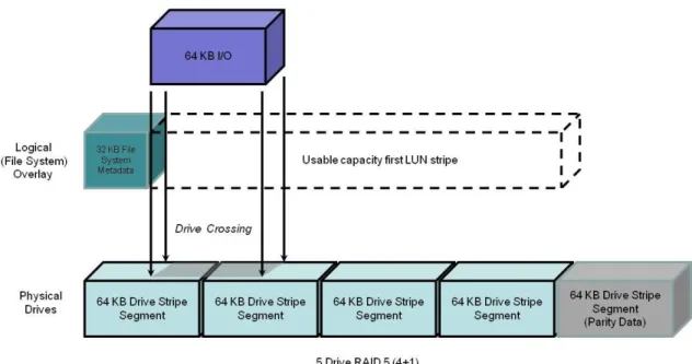
The common example is shown in Figure 1. Some Intel-based systems are misaligned due to metadata written by the BIOS. For example, the 63 drive block NTFS header at the beginning of a LUN can cause misalignment. In an aligned system, up to a 64 KB write can be serviced by a single drive. However, metadata can cause an offset in the address space of a RAID group stripe. This offset causes I/O requests that would normally only require servicing by a single drive, to require two drives.
Figure 1 Effect of misalignment with a 63-block (32 KB) metadata area
Knowing the I/O type (random or sequential) and size of the workload is important in understanding the benefits of alignment. The type and size of a data transfer is application-dependent.
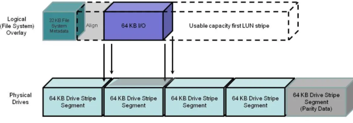
With its default 64 KB stripe element size, all I/Os larger than 64 KB will involve drive crossings. To minimize the number of crossings by 64 KB and smaller I/Os, partitions can be aligned to be on a RAID group stripe boundary. Figure 2. Aligned I/O with 65 block (33 KB) Alignment Space addedshows an aligned partition with a 64 KB I/O.
When a specific file system or application encourages the use of an aligned address space, and the offset is declared, EMC recommends using a host operating system drive utility be used to adjust the partitions. The adjustment requires offsetting the start of the LUNs usable data to begin on a drive stripe segment boundary. The Unisphere LUN bind offset facility should be used with caution, since it can adversely affect array replication synchronization rates.
Either host based or Unisphere based, alignment may be used with the same effect. Do not use both of them at the same time.
Note that not all I/O workloads require alignment. Misalignment rarely affects applications with small I/Os in comparison to the stripe segment size. Only occasionally will a small I/O result in a disk crossing. It is more likely to ‗fit‘ with its peers on one disk or the next.
For example, workloads of predominantly 4 KB I/Os will see only a small advantage from alignment. As previously noted, 4KB is a common file system I/O block size.
However, expect to see some drive crossings, even with small I/Os. This can result from file headers, file system block size, and file system metadata, which may be part of the workload‘s I/O. As a result, an aligned partition, and a file system using 4 KB blocks, but serving an application reading a 4 KB header, which then requests a 16 KB I/O from the file can create a larger I/O of an odd size. This originally small-block I/O on an aligned partition could result in occasional drive crossings.
Figure 2. Aligned I/O with 65 block (33 KB) Alignment Space added
Enterprise-level applications such as databases (Oracle, SQL Server, or IBM UDB/DB2) supporting multiple block sizes will see a positive performance effect from alignment when the larger (8 KB and 16 KB) block size is used.
File-system alignment procedure
Detailed information and instructions for performing file-system alignments for host operating systems can be found on Powerlink.
Microsoft-based file-system alignment procedure
For Microsoft-based file systems refer to the white paper Using diskpar and diskpart to Align Partitions on Windows Basic and Dynamic Disks. For VMware alignment, the Using EMC CLARiiON Storage with VMware Infrastructure and vSphere Environments TechBook is a good source.
Alignment of Microsoft Windows Server partitions may not be necessary. Microsoft Windows Server 2008 LUNs, are automatically aligned. Its partitions are offset automatically by the O/S to 1 MB. This provides good alignment for the element segments used by the storage system. In addition, be aware that Windows Server 2008 defaults to a smaller offset for small capacity drives.
Microsoft Windows Server 2003 and earlier O/S revision partitions may benefit from alignment. Use the DiskPart command utility to align Microsoft Windows Server 2003 SP1 or earlier. To align a basic disk, use the align parameter to create a partition:
diskpart> create partition primary align = 1024
This makes the partition start at sector 2048. After aligning the drive, assign a drive letter to the partition before NTFS formatting. For more information about using the DiskPart command please refer to Microsoft Windows Server documentation.
Be aware, you cannot use the align command for dynamic disks; you must use the DiskPart command utility.
Linux file-system alignment procedure
With Linux host O/S installations, align the partition table first using the fdisk utility with instructions provided on the man page.
The following procedure using fdisk may be used to create a single aligned partition on a second Linux file sda or sdc file-system LUN utilizing all the LUN‘s available capacity. In this example, this partition will be:
/dev/nativedevicename. The procedure is:
fdisk /dev/nativedevicename # sda and sdc n # New partition
p # Primary 1 # Partition 1
<Enter> # 1st cylinder=1
<Enter> # Default for last cylinder # Expert mode
b # Starting block 1 # Partition 1
128 # Stripe element = 128 w # Write
Aligning Linux file-system very large LUNs
To create an aligned partition larger than 2 TB the GUID Partition Table (GPT) drive partitioning scheme needs to be used. GPT is part of the Extensible Firmware Interface (EFI) initiative. GPT provides a more flexible mechanism for partitioning drives than the older Master Boot Record (MBR) partitioning scheme.
By default, a GPT partition is misaligned by 34 blocks. In Linux, use the parted utility to create and align a GPT partition.
The following procedure describes how to make a partition larger than 2 TB. In this example, this partition will be /dev/sdx. The mkpart command aligns a 2.35 TB partition to a 1 MB starting offset.
Following are the Linux commands needed to create a GPT partition: # parted /dev/sdb
GNU Parted 1.6.19 Using /dev/sdb (parted) mklabel gpt (parted) p
Disk geometry for /dev/sdb: 0.000-2461696.000 megabytes Disk label type: gpt
Minor Start End Filesystem Name Flags (parted) mkpart primary 1 2461696
(parted) p
Disk geometry for /dev/sdb: 0.000-2461696.000 megabytes Disk label type: gpt
Minor Start End Filesystem Name Flags 1 1.000 2461695.983
(parted) q
Availability
The following sections describe the host system availability Best Practices.
PowerPath
Failover is the detection of an I/O failure and the automatic transfer of the I/O to a backup I/O path. The host-resident EMC PowerPath® software integrates failover, multiple path I/O
capability, automatic load balancing, and encryption. If available on the OS, we recommend PowerPath—whether for a single-attach system through a switch (which allows host access to continue during a software update), or in a fully redundant system.
A recommended introduction to PowerPath and its considerations is available in the latest revision of the EMC PowerPath Product Guide available on Powerlink.
Port load balancing
PowerPath allows the host to connect to a LUN through more than one SP port. This is known as
multipathing. PowerPath optimizes multipathed LUNs with load-balancing algorithms. It offers several load-balancing algorithms. Port load balancing equalizes the I/O workload over all available channels. We recommend the default algorithm, ClarOpt, which adjusts for number of bytes transferred and for the queue depth.
Hosts connected to VNX‘s benefit from multipathing. Direct-attach multipathing requires at least two HBAs; SAN multipathing also requires at least two HBAs. Each HBA needs to be zoned to more than one SP port. The advantages of multipathing are:
Failover from port to port on the same SP, maintaining an even system load and minimizing LUN trespassing
Port load balancing across SP ports and host HBAs
Higher bandwidth attach from host to storage system (assuming the host has as many HBAs as paths used)
While PowerPath offers load balancing across all available active paths, this comes at some cost: Some host CPU resources are used during both normal operations, as well as during failover. Every active and passive path from the host requires an initiator record; there are a finite number of initiators per system.
Active paths increase time to fail over in some situations. (PowerPath tries several paths before trespassing a LUN from one SP to the other.)
Because of these factors, active paths should be restricted, via zoning, to two storage system ports per HBA for each storage system SP to which the host is attached. The exception is in
environments where bursts of I/O from other hosts sharing the storage system ports are unpredictable and severe. In this case, four storage system ports per HBA should be used. The EMCPowerPath Version 5.5 Product Guide available on Powerlink provides additional details on PowerPath configuration and usage.
Other multipath I/O services (MPIO)
Services other than PowerPath may be used to perform the MPIO function. These applications perform similarly to PowerPath, although they may not have the all the features or as close an integration with the storage system as available with PowerPath.
Microsoft Multi-Path I/O
Microsoft Multi-Path I/O (MPIO) as implemented by MS Windows Server 2008 provides a similar, but more limited, multipathing capability than PowerPath. Features found in MPIO include failover, failback, Round Robin Pathing, weighted Pathing, and I/O Queue Depth management.
Review your Microsoft Server O/S‘s documentation for information on available MPIO features and their implementation.
Linux MPIO
Linux MPIO is implemented by Device Mapper ( ). It provides a similar, but more limited, multipathing capability than PowerPath. The MPIO features found in Device Mapper are dependent on the Linux release and the revision.
Review the Native Multipath Failover Based on DM-MPIO for v2.6.x Linux Kernel and EMC Storage ArraysConfiguration Guide available on Powerlink for details and assistance in configuring Device Mapper.
ALUA (Asymmetric Logical Unit Access)
Asymmetric Logical Unit Access (ALUA) can reduce the effect of some front- and back-end failures to the host. It provides path management by permitting I/O to stream to either or both of the storage system‘s storage processors without trespassing. It follows the SCSI SPC-3 standard for I/O routing. The white paper EMC CLARiiON Asymmetric Active/Active Feature available on
Powerlink provides an in-depth discussion of ALUA features and benefits.
Host considerations
PowerPath versions 5.1 and later are ALUA-compliant releases. Ensure usage of PowerPath version 5.1 or later, with the host operating system.
PowerPath load balances across optimized paths. It only uses non-optimized paths if all the original optimized paths have failed. For example when an optimized path to the original owning SP fails, it sends I/O via the non-optimal path to the peer SP. If path or storage processor failures occur, PowerPath initiates a trespass to change LUN ownership. That is, the non-optimized path becomes the optimized path, and the optimized path becomes the non-optimized paths.
Not all multipathing applications or revisions are ALUA compliant. Verify that your revision of MPIO or other native host-based failover application can interoperate with ALUA.
When configuring PowerPath on hosts that can use ALUA, the default storage system failover mode is: Failover Mode 4. This configures the VNX for asymmetric Active/Active operation. This has the advantage of allowing I/O to be sent to a LUN regardless of LUN ownership. Details on the separate failover modes 1 through 4 can be found in the EMC CLARiiON Asymmetric Active/Active Feature — A Detailed Review white paper, available on Powerlink.
O/S considerations
To take advantage of ALUA features, host operating system needs to be ALUA-compliant. Several operating systems support native failover with Active/Passive (A/P) controllers. However, there are exceptions. Refer to the appropriate support guide for O/S support. For example, ALUA supported Linux operating systems would be found in the EMC® Host Connectivity Guide for Linux, Rev A23 or higher.
Performance considerations
The optimized path is the normal operation path. ALUA has no effect on optimized path performance.
The non-optimized path is the alternate path accessed using ALUA. Performance can be adversely affected on the non-optimized path.
Host I/O requests received over non-optimized paths are received by the storage processor not owning the destination LUN. These requests are then forwarded to the peer storage processor owning the LUN. This storage processor executes the I/O as though the request had been received directly. When the I/O completes, data or acknowledgements are forwarded back through the requesting storage processor to be transmitted to the host.
The redirection, from storage processor to peer storage processor and back, increases I/O response time. The duration of the delay is dependent on the overall storage system, storage processor workloads, and the size of the I/O. Expect a 10-20 percent decrease in maximum IOPS, and up to a 50 percent decrease in bandwidth with non-optimum path usage.
Monitoring ALUA performance
A number of metrics have been created to describe requests arriving over optimized versus non-optimized paths. This path usage can be monitored through Unisphere Analyzer. In addition, metrics exist for total I/O over all paths. These metrics describe the utilization of paths and the differences in performance. Information on how to use Unisphere Analyzer can be found in the Unisphere on-line Help feature.
Queuing, concurrency, queue-full (QFULL)
A high degree of request concurrency results in the best storage system resource utilization. This is achieved by having many host connections per storage processor front-end port. However, if a storage system‘s queues become full, it will respond with a queue-full (QFULL) flow control command. The storage system‘s front-end port drivers return a QFULLstatus command under two conditions:
The practical maximum number of concurrent host requests at the port is above 1600 (port queue limit).
The total number of requests for a given LUN is (14 * (the number of data drives in the LUN) ) + 32
The host response to a QFULL is HBA-dependent, but it typically results in a suspension of activity for more than one second. Though rare, this can have serious consequences on throughput if it happens repeatedly. See Host HBAs section.
The best practices 1600 port queue limit allows for ample burst margin. In most installations, the maximum load can be determined by summing the possible loads for each host HBA accessing the port and adjusting the HBA LUN settings appropriately. (Some operating system drivers permit limiting the HBA concurrency on a global level regardless of the individual LUN settings.) In complex systems that are make-up of many hosts, each with several HBAs, it may be difficult to compute the worst-case load scenario. In this case, use the default settings on the HBA and if QFULL is suspected, use Unisphere Analyzer (release 31 or later) to determine if the storage system‘s front-end port queues are full by following the steps described below.
Typically the queue depth setting for ESX and UNIX is 32. On Windows hosts using the QLogic HBA‘s and the EMC default driver settings, the queue depth is set to 256. This is called the
Execution Throttle. This setting is a target setting and may be too high in some cases. If there is indication of QFULL problems, lower it to 32.
HBA queue depth settings usually eliminate the possibility of LUN generated QFULL. For instance, a RAID 5 4+1 device would require 88 parallel requests ((14*4) + 32) before the port would issue QFULL. If the HBA queue-depth setting is 32, then the limit will never be reached. A common exception is the RAID 1/0 (1+1).
For example, if the HBA queue-depth default setting was altered to a larger value (such as 64) to support greater concurrency for large MetaLUNs owned by the same host, the RAID 1/0 device could reach queue-full because its limit is 46 requests(1*14)+32).
QFULL is never generated as a result of a drive‘s queue-depth.
Port statistics are collected for Unisphere Analyzer; this data includes several useful statistics for each individual port on the SP:
Port queue-full – a counter has been added showing the number of QFULL signals issued due to port queue overflow
Per-port bandwidth and IOPS Usage
Consider all hosts connected to the storage system, and which LUNs they access. If necessary, set HBA throttles to limit concurrent requests to each LUN. Depending on the operating system, it may be possible to globally limit the total outstanding requests per HBA or per target. Set the HBA throttles of the hosts sharing a port so the total cannot exceed the port queue limit.
Remember that multipathing to one LUN via multiple ports on the same SP may lead to exceeding the port queue limit.
If high concurrency is suspected and performance problems occur, check port statistics reported by Unisphere Analyzer for queue-fulls, and lower the HBA throttles if appropriate.
Storage network attachment
Hosts use:
Fibre Channel HBAs to connect to Fibre Channel storage networks
Fibre Channel over Ethernet (FCoE) CNAs to connect to via an Ethernet network to storage Network interface card (NIC), iSCSI HBAs, and TCP/IP Offload Engines (TOE) with iSCSI drivers connect to Ethernet network for iSCSI storage network support.
Host bus
Knowing the number, distribution, and speed of the host‘s buses is important to avoid bottlenecks within the host. The host‘s I/O bus is sometimes called the peripheral bus. Ensure the network adapter‘s full bandwidth is supported by the host‘s I/O bus hardware.
Entry-level and legacy hosts may have less internal I/O bus bandwidth than their network adapters or HBAs. For this reason it is important to verify that your host can handle the
bandwidth of the network interfaces when using these protocols: Fibre Channel networks that are equal to or faster than 4 Gb/s; 10 Gb/s Ethernet; and 10 Gb/s Fibre Channel over Ethernet (FCoE). In addition, when more than one adapter is present on a host I/O bus, remember that these adapters share the available bus bandwidth, and it is possible for the summed bandwidth requirement of the adapters to exceed the host‘s available bus bandwidth.
The ratio of network adapter ports to buses needs to be known. A host may have more than one internal bus. The distribution of bus slots accepting network adapters to buses is not always obvious. Review the number of network adapters, and the number of ports per network adapter that are being attached to each of a host‘s individual buses. Ensure that network adapters are connected to fast (>66 MHz) and wide (64-bit) PCI, PCI-X, and four-lane (x4) or greater PCI Express (PCIe) 1.1 or 2.X host buses. In all cases, the host I/O bus bandwidth needs to be greater than the summed maximum bandwidth of the network adapters to avoid a bottleneck.
Be aware that PCIe 2.0 connectors on host buses may internally provide fewer lanes than the physical connector. In addition, when more than one HBA is slotted the number of available lanes will be divided between the HBAs. This will reduce overall bandwidth to all HBAs.
Fibre Channel HBAs
High availability requires at least two HBA connections to provide redundant paths to the storage network or if directly connected, to the storage system.
It is a best practice to have redundant HBAs. Using more than one single-port HBA enables port- and path-failure isolation, and may provide performance benefits. Using a multiport HBA provides a component cost savings and efficient port management that may provide a
performance advantage. Multiport HBAs are useful for hosts with few available I/O bus slots. The liability is a multiport HBA presents a single point of failure for several ports. Otherwise, with a single-ported HBA, a failure would affect only one port.
HBAs should also be placed on separate host buses for performance and availability. Note this may not be possible on smaller hosts that have a single bus or a limited number of bus slots. In this case, multiport HBAs are the only option.
Always use an HBA rated for or exceeding the bandwidth of the storage network‘s maximum bandwidth. Ensure that legacy 2 Gb/s or slower HBAs are not used for connections to 4 Gb/s or higher SANs.
FC SANs reduce the speed of the network path to the HBA‘s lower speed either as far as the first connected switch, or to the storage system‘s front-end port when directly connected. This may bottleneck the overall network when bandwidth is intended to be maximized.
Finally, using the most current HBA firmware and driver from the manufacturer is always recommended. The Unified Procedure Generator (installation available through Powerlink) provides instructions and the configuration settings for HBAs specific to your storage system.
FCoE Converged Network Adapter (CNA)
Contact your EMC Sales representative to engage an EMC USPEED Professional for assistance with CNA performance.
Network interface cards (NIC), TCP/IP offload engines (TOE), and iSCSI host bus adapters (HBA)
Three host devices connect hosts to iSCSI SANs: NICs
iSCSI HBAs. iSCSI TOEs
The differences in the devices include cost, host CPU utilization, and features, such as security. The same server cannot use NICs and HBAs to connect to the same VNX or CLARiiON storage system. If there are multiple storage systems, the same host can connect through NICs and HBAs to the separate storage systems at the same time.
iSCSI NICs
NICs are the typical way of connecting a host to an Ethernet network. They are supported by software iSCSI initiators on the host.
Ethernet networks will auto-negotiate down to the lowest common device speed. Using a lower-rated NIC may bottleneck the storage network‘s bandwidth. Always use a NIC lower-rated for or exceeding the bandwidth of the available Ethernet network. Do not use legacy 10 Mb/s or 100 Mb/s NICs for iSCSI SAN connections to 1 Gb/s or higher Ethernet networks.
iSCSI HBAs
The decision to use an iSCSI HBA versus a TOE, versus a NIC is dependent on the percentage CPU utilization of the host when it is processing workload(s). On small hosts, and hosts with high CPU utilizations, a TOE or iSCSI HBA can lower the host‘s CPU utilization. However, using an HBA or TOE may increase workload response time. In addition, an iSCSI HBA or TOE costs more than a conventional NIC. On large hosts or hosts not affected by high CPU
utilization, we recommend a conventional NIC. Note that to work on an iSCSI SAN, the NIC must support the iSCSI protocol on the host. Check with the NIC‘s manufacturer for the appropriate driver support.
iSCSI TOEs
A TOE is a faster type of NIC. A TOE has on-board processors to handle TCP packet
segmentation, checksum calculations, and optionally IPSec (security) offload from the host CPU on to themselves. This allows the host CPU(s) to be used exclusively for application processing. In general, iSCSI HBAs are the most scalable interface. On iSCSI HBAs the TCP/IP and iSCSI processing is offloaded to the HBA. This reduces host CPU utilization. An iSCSI HBA also allows booting off an iSCSI target. This is an important consideration when considering diskless host booting. HBAs also typically provide for additional services such as security.
General Recommendations
Redundant NICs, iSCSI HBAs, and TOEs should be used for availability. NICs may be either single or multiported. A host with a multiported NIC or more than one NIC is called a
multihomed host. Typically, each NIC or NIC port is configured to be on a separate subnet.
Ideally, when more than one NIC is provisioned, they should also be placed on separate host buses. Note this may not be possible on smaller hosts having a single bus or a limited number of bus slots, or when the on-board host NIC is used.
All NICs do not have the same level of performance. This is particularly true of host on-board (mainboard) NICs, 10 Gb/s NICs, and 10 Gb/s HBAs. For the most up-to-date compatibility information, consult the EMC Support Matrix (ESM), available through E-Lab Interoperability Navigator (ELN) at: http://elabnavigator.EMC.com.
Finally, using the current iSCSI initiator, NIC, TOE, or iSCSI HBA firmware and driver from the manufacturer is always recommended.
Chapter 2 Network Best
Practices
Network best practices advise on the software and hardware configurations of the iSCSI and Fibre Channel network infrastructure that attaches hosts to storage systems and their effect overall storage system performance and availability.
A recommended introduction to storage system networks and networking performance considerations can be found in the EMC Networked Storage Topology Guide available on
Powerlink.
Performance
The following sections describe the best practices for the storage system that may be applied to the storage network.
iSCSI protocol
Avoiding iSCSI network congestion is the primary consideration for achieving iSCSI LAN performance. It is important to take into account network latency and the potential for port oversubscription when configuring your network. Network congestion is usually the result of an ill-suited network configuration or improper network settings. Ill-suited may be a legacy CAT5 cable in-use on a GigE link. Network settings include IP overhead and protocol configuration of the network‘s elements.
For example a common problem is a switch in the data path into the storage system that is fragmenting frames.
As a minimum, the following recommendations should be reviewed to ensure the best performance.
Simple network topology
Both bandwidth and throughput rates are subject to network conditions and latency. It is common for network contentions, routing inefficiency, and errors in LAN and VLAN configuration to adversely affect iSCSI performance. It is important to profile and periodically monitor the network carrying iSCSI traffic to ensure the consistently high Ethernet network performance.
In general, the simplest network topologies offer the best performance. Minimize the length of cable runs, and the number of cables, while still maintaining physically separated redundant connections between hosts and the storage system(s).
Avoid routing iSCSI traffic as this will introduce latency. Ideally the host and the iSCSI front-end port are on the same subnet and there are no gateways defined on the iSCSI ports. If they are not on the same subnet, users should define static routes. This can be done per target or subnet using naviseccli connection –route.
Network latency
Latency can contribute substantially to iSCSI-based storage system‘s performance. As the distance from the host to the storage system increases; a latency of about 1 millisecond per 200 kilometers (125 miles) is introduced. This latency has a noticeable effect on WANs supporting sequential I/O workloads.
For example, a 40 MB/s 64 KB single stream would average 25 MB/s over a 200 km distance. EMC recommends increasing the number of streams to maintain the highest bandwidth with these long-distance, sequential I/O workloads.
Bandwidth-balanced configuration
A balanced bandwidth iSCSI configuration is when the host iSCSI initiator‘s bandwidth is greater than or equal to the bandwidth of its connected storage system‘s ports. Generally, configure each host NIC or HBA port to only two storage system ports (one per SP). One storage system port should be configured as active, and the other to standby. This avoids oversubscribing a host‘s ports.
Network settings
Manually override auto-negotiation on the host NIC or HBA and network switches for the following settings. These settings improve flow control on the iSCSI network:
Jumbo frames Pause frames TCP Delayed ACK Jumbo frames
Using jumbo frames can improve iSCSI network bandwidth by up to 50 percent. When supported by the network, we recommend using jumbo frames to increase bandwidth.
Jumbo frames can contain more iSCSI commands and a larger iSCSI payload than normal frames without fragmenting or with less fragmenting depending on the payload size. On a standard Ethernet network the frame size is 1500 bytes. Jumbo frames allow packets configurable up to 9,000 bytes in length.
The VNX series supports 4,000, 4,080, or 4,470 MTUs for its front-end iSCSI ports. It is not recommended to set your storage network for Jumbo frames to be any larger then these. If using jumbo frames, all switches and routers in the paths to the storage system must support and be capable of handling and configured for jumbo frames. For example, if the host and the storage system‘s iSCSI ports can handle 4,470-byte frames, but an intervening switch can only handle 4,000 bytes, then the host and the storage system‘s ports should be set to 4,000 bytes. Note that the File Data Mover has a different Jumbo frame MTU than the VNX front-end ports. The larger Data Mover frame setting should be used. See the File Best Practices for details. Pause frames
Pause frames are an optional flow-control feature that permits the host to temporarily stop all traffic from the storage system. Pause frames are intended to enable the host‘s NIC or HBA, and the switch, to control the transmit rate.
Due to the characteristic flow of iSCSI traffic, pause frames should be disabled on the iSCSI network used for storage. They may cause delay of traffic unrelated to specific host port to storage system links.
TCP Delayed ACK
On MS Windows, and ESX-based hosts, TCP Delayed ACK delays an acknowledgement for a received packet for the host.