Check Point FireWall-1 Guide
NG FP3
For additional technical information about Check Point products, consult Check Point’s SecureKnowledge at
http://support.checkpoint.com/kb/
Part No.: 700527 September 2002
© 2000-2002 Check Point Software Technologies Ltd.
All rights reserved. This product and related documentation are protected by copyright and distributed under licensing restricting their use, copying, distribution, and decompilation. No part of this product or related documentation may be reproduced in any form or by any means without prior written authorization of Check Point. While every precaution has been taken in the preparation of this book, Check Point assumes no responsibility for errors or omissions. This publication and features described herein are subject to change without notice.
RESTRICTED RIGHTS LEGEND:
Use, duplication, or disclosure by the government is subject to restrictions as set forth in subparagraph (c)(1)(ii) of the Rights in Technical Data and Computer Software clause at DFARS 252.227-7013 and FAR 52.227-19.
TRADEMARKS:
Check Point, the Check Point logo, ClusterXL, ConnectControl, FireWall-1, FireWall-1, FireWall-1 GX, FireWall-1 SecureServer, FireWall-1 SmallOffice, FireWall-1 VSX, FireWall-1 XL, FloodGate-1, INSPECT, INSPECT XL, IQ Engine, Open Security Extension, OPSEC, Provider-1, SecureKnowledge, SecurePlatform, SecureXL, SiteManager-1, SmartCenter, SmartCenter Pro, SmartDashboard, SmartDefense, SmartLSM, SmartMap, SmartUpdate, SmartView, SmartView Monitor, SmartView Reporter, SmartView Status, SmartView Tracker, SVN, UAM, User-to-Address Mapping, UserAuthority, VPN-1, VPN-1 Accelerator Card, VPN-1 Appliance, VPN-1 Certificate Manager, VPN-1 Gateway, VPN-1 Net, VPN-1 Pro, VPN-1 SecureClient, VPN-1 SecureClient, VPN-1 SecuRemote, VPN-1 SecureServer VPN-1 SmallOffice and VPN1 VSX are trademarks or registered trademarks of Check Point Software Technologies Ltd. or its affiliates. All other product names mentioned herein are trademarks or registered trademarks of their respective owners.
The products described in this document are protected by U.S. Patent No. 5,606,668, 5,699,431 and 5,835,726 and may be protected by other U.S. Patents, foreign patents, or pending applications.
THIRD PARTIES:
Entrust is a registered trademark of Entrust Technologies, Inc. in the United States and other countries. Entrust’s logos and Entrust product and service names are also trademarks of Entrust Technologies, Inc. Entrust Technologies Limited is a wholly owned subsidiary of Entrust Technologies, Inc. FireWall-1 and SecuRemote incorporate certificate management technology from Entrust.
Verisign is a trademark of Verisign Inc.
The following statements refer to those portions of the software copyrighted by University of Michigan.
Portions of the software copyright © 1992-1996 Regents of the University of Michigan. All rights reserved. Redistribution and use in source and binary forms are permitted provided that this notice is preserved and that due credit is given to the University of Michigan at Ann Arbor. The name of the University may not be used to endorse or promote products derived from this software without specific prior written permission. This software is provided “as is” without express or implied warranty.
Copyright © Sax Software (terminal emulation only).
The following statements refer to those portions of the software copyrighted by Carnegie Mellon University.
Copyright 1997 by Carnegie Mellon University. All Rights Reserved.
Permission to use, copy, modify, and distribute this software and its documentation for any purpose and without fee is hereby granted, provided that the above copyright notice appear in all copies and that both that copyright notice and this permission notice appear in supporting documentation, and that the name of CMU not be used in advertising or publicity pertaining to distribution of the software without specific, written prior permission.
CMU DISCLAIMS ALL WARRANTIES WITH REGARD TO THIS SOFTWARE, INCLUDING ALL IMPLIED WARRANTIES OF MERCHANTABILITY AND FITNESS, IN NO EVENT SHALL CMU BE LIABLE FOR ANY SPECIAL, INDIRECT OR
CONSEQUENTIAL DAMAGES OR ANY DAMAGES WHATSOEVER RESULTING FROM LOSS OF USE, DATA OR PROFITS, WHETHER IN AN ACTION OF CONTRACT, NEGLIGENCE OR OTHER TORTIOUS ACTION, ARISING OUT OF OR IN CONNECTION WITH THE USE OR PERFORMANCE OF THIS SOFTWARE. The following statements refer to those portions of the software copyrighted by The Open Group.
THE SOFTWARE IS PROVIDED "AS IS", WITHOUT WARRANTY OF ANY KIND, EXPRESS OR IMPLIED, INCLUDING BUT NOT LIMITED TO THE WARRANTIES OF MERCHANTABILITY, FITNESS FOR A PARTICULAR PURPOSE AND
NONINFRINGEMENT. IN NO EVENT SHALL THE OPEN GROUP BE LIABLE FOR ANY CLAIM, DAMAGES OR OTHER LIABILITY, WHETHER IN AN ACTION OF CONTRACT, TORT OR OTHERWISE, ARISING FROM, OUT OF OR IN CONNECTION WITH THE SOFTWARE OR THE USE OR OTHER DEALINGS IN THE SOFTWARE. The following statements refer to those portions of the software copyrighted by The OpenSSL Project.
This product includes software developed by the OpenSSL Project for use in the OpenSSL Toolkit (http://www.openssl.org/).*
THIS SOFTWARE IS PROVIDED BY THE OpenSSL PROJECT ``AS IS'' AND ANY * EXPRESSED OR IMPLIED WARRANTIES, INCLUDING, BUT NOT LIMITED TO, THE IMPLIED WARRANTIES OF MERCHANTABILITY AND FITNESS FOR A PARTICULAR PURPOSE ARE DISCLAIMED. IN NO EVENT SHALL THE OpenSSL PROJECT OR ITS CONTRIBUTORS BE LIABLE FOR ANY DIRECT, INDIRECT, INCIDENTAL, SPECIAL, EXEMPLARY, OR CONSEQUENTIAL DAMAGES (INCLUDING, BUT NOT LIMITED TO, PROCUREMENT OF SUBSTITUTE GOODS OR SERVICES; LOSS OF USE, DATA, OR PROFITS; OR BUSINESS INTERRUPTION) HOWEVER CAUSED AND ON ANY THEORY OF LIABILITY, WHETHER IN CONTRACT, STRICT LIABILITY, OR TORT (INCLUDING NEGLIGENCE OR OTHERWISE) ARISING IN ANY WAY OUT OF THE USE OF THIS SOFTWARE, EVEN IF ADVISED OF THE POSSIBILITY OF SUCH DAMAGE.
The following statements refer to those portions of the software copyrighted by Eric Young.
THIS SOFTWARE IS PROVIDED BY ERIC YOUNG ``AS IS'' AND ANY EXPRESS OR IMPLIED WARRANTIES, INCLUDING, BUT NOT LIMITED TO, THE IMPLIED WARRANTIES OF MERCHANTABILITY AND FITNESS FOR A PARTICULAR PURPOSE ARE DISCLAIMED. IN NO EVENT SHALL THE AUTHOR OR
CONTRIBUTORS BE LIABLE FOR ANY DIRECT, INDIRECT, INCIDENTAL, SPECIAL, EXEMPLARY, OR CONSEQUENTIAL DAMAGES (INCLUDING, BUT NOT LIMITED TO, PROCUREMENT OF SUBSTITUTE GOODS OR SERVICES; LOSS OF USE, DATA, OR PROFITS; OR BUSINESS INTERRUPTION) HOWEVER CAUSED AND ON ANY THEORY OF LIABILITY, WHETHER IN CONTRACT, STRICT LIABILITY, OR TORT (INCLUDING NEGLIGENCE OR OTHERWISE) ARISING IN ANY WAY OUT OF THE USE OF THIS SOFTWARE, EVEN IF ADVISED OF THE POSSIBILITY OF SUCH DAMAGE.
Copyright © 1998 The Open Group.
S
ep
tem
ber 2002
Check Point Software Technologies Ltd.
Please direct all comments regarding this publication to [email protected]. International Headquarters:
3A Jabotinsky Street Ramat Gan 52520, Israel Tel: 972-3-753 4555 Fax: 972-3-575 9256
U.S. Headquarters:
Three Lagoon Drive, Suite 400 Redwood City, CA 94065
Tel: 800-429-4391; (650) 628-2000 Fax: (650) 654-4233
Table Of Contents
Preface
Who Should Use this User Guide 9 Summary of Contents 9Check Point Documentation 10 What Typographic Changes Mean 12 Shell Prompts in Command Examples 13 Network Topology Examples 13
Chapter 1
SmartDefense
Overview 15
Configuring SmartDefense 16 Anti Spoofing Configuration 17 Denial of Service 18
Teardrop 20 Ping of Death 21 LAND 22 IP and ICMP 22
Fragment Sanity Check 24 Packet Sanity 25
Max Ping Size 26 TCP 26
SYN Attack 27 Small PMTU 30 Sequence Verifier 32 DNS 33
FTP 34
FTP Bounce Attack 35 FTP Security Server 36 HTTP 42
General HTTP Worm Catcher 43 HTTP Security Server 44 SMTP Security Server 48
SMTP Content 49
Mail and Recipient Content 50 Successive Events 52
Address Spoofing 53 Port Scanning 55
Local Interface Spoofing 56 Successive Alerts 57
Successive Multiple Connections 58 SYN Attacks and SYNDefender 58
Chapter 2
Network Address Translation (NAT)
Introduction 67
The Need for Address Translation 67 Example 69
Configuring Network Address Translation 70 Address Translation Modes 70
Hide Mode 71
Statically Translating Addresses 75 Address Translation and Routing 78
Configuring Routing on the Gateway 78 IANA Recommendations 86
Supported Services 86 Restrictions 86 FTP port command 87
Generating Address Translation Rules Automatically 87 Overview 87
Network Address Translation Rule Base 89 Overview 89
Structure of a NAT Rule 89 NAT Rule Base Example 91
Defining Address Translation Rules 93 Using the NAT Rule Base Editor 93 Address Translation Examples 102
Gateway with Two Interfaces 102 Gateway with Three Interfaces 106 Advanced Topics 112
Rule Base 112 Overlapping NAT 113 Implementation 116
Frequently Asked Questions 116
Chapter 3
Authentication
Overview 123
VPN-1/FireWall-1 Authentication 123 Three Types of Authentication 124 User Authentication 126
User Authentication — Overview 127 User Authentication — Deployment 127 Non-Transparent User Authentication 140
User Authentication and the HTTP Security Server - 142 Session Authentication 162
Session Authentication — Overview 162 Session Authentication — Deployment 164 Client Authentication 173
Client Authentication — Overview 173 Client Authentication — Deployment 177
Encrypted Client Authentication 201
Client Authentication — Security Considerations 202 Client Authentication — Additional Features 202
Chapter 4
Security Servers and Content Security
Security Servers 205 Overview 205
Security Servers and the Rule Base 208 Interaction with OPSEC Products 222 Defining Security Servers 224 Content Security 227
Resources and Security Servers 228 Web (HTTP) 230
Mail (SMTP) 233 FTP 234
CVP Inspection 234
CVP Load Sharing and Chaining 236 Security Server Configuration 237
fwauthd.conf file 237
Chapter 5
ClusterXL
Installing and Licensing ClusterXL 241 State Synchronization 243
Full and Delta Synchronization 243 Secured Interfaces 244
Implementing Synchronization 244 Selective Synchronization 245
Different Routes for Connections (Asymmetric Routing) 246 Timing Issues 247
Synchronized Cluster Restrictions 248 Troubleshooting State Synchronization 249
Check Point High Availability and Load Sharing Solutions 250 High Availability —Overview 250
Load Sharing—Overview 250 High Availability Modes 251 Improvements in Load Sharing 252 When Does a Failover Occur? 252
What Happens When a Gateway Recovers? 253 VLAN Support 253
How a Recovered Cluster Member Obtains the Latest Security Policy 253 Cluster Protocols 254
Configuring High Availability and Load Sharing 255 Example New CPHA and Load Sharing Topology 255 Example Legacy CPHA Topology 257
Moving from a Single Enforcement Module to Load Sharing or New CPHA 260 Configuring Load Sharing or New CPHA from Scratch 264
Moving Between New CPHA and Load Sharing 268
Configuring Legacy CPHA from Scratch 271
Upgrading a Check Point High Availability Cluster 273 Upgrading a Third Party cluster 274
Adding Another Member to an Existing Cluster 274
Moving from Load Sharing or New CPHA to Legacy CPHA 274 Multicast Switch Settings for Load Sharing 275
ClusterXL Advanced Settings 276
High Availability and Load Sharing Commands 278 Cluster Status Tools 278
To Verify that Load Sharing Works Properly 278 Status Manager 279
Log Viewer 280
Chapter 6
VoIP (Voice Over IP)
Overview 281 H.323-Based VoIP 281
Configuring VoIP (H.323) 282 SIP-Based VoIP 288
Configuration 288
Configuring VoIP (SIP) 289
Chapter 7
Boot Security
The Need for Boot Security 295 Control of IP Forwarding 296 The Default Filter 296
Why the Default Filter is Needed 296 What the Default filter Does 296 Default Filter Operation 297 The Initial Policy 298
Stopping VPN-1/FireWall-1 for Remote Maintenance 300 fwstop -default and fwstop -proc 300
Changing Boot Security Settings 301 Verifying the Default Filter 301 control_bootsec 301
fwboot bootconf 302 comp_init_policy 303 Standard Default Filter 303
defaultfilter.boot 304 defaultfilter.drop 304 To change the Default Filter 304
User-Defined Default Filter 304
To unload a Default Filter or an Initial Policy 305 Boot Security FAQ 305
VPN-1/FireWall-1 HP OpenView Extension 310 Installing the FireWall-1 HP OpenView Extension 310
Uninstalling the VPN-1/FireWall-1 HP OpenView Extension 312 Viewing FireWalled Objects 312
VPN-1/FireWall-1 MIB Source 314
Chapter 9
ConnectControl — Server Load Balancing
The Need for Server Load Balancing 319 How Server Load Balancing Works 320
Load Balancing using HTTP Logical Server 320 Load Balancing using Non–HTTP Logical Server 321 Load Balancing Algorithms 322
Defining Logical Servers 322 Rule Base 325
Using HTTP Logical Servers in a Rule 325 Using non-HTTP Logical Servers in a Rule 325 Load Measuring 325
Chapter 10
FAQ (Frequently Asked Questions)
Defining Objects and Services 327 Daemons 332
Security Servers 333 Logging 337 Security 338
VPN-1/FireWall-1/n (VPN-1/FireWall-1/25, VPN-1/FireWall-1/50, etc.) Issues 339 Supported Protocols and Interfaces 341
Inspecting 342 342
Administrative Issues 343 Performance 344
Preface
Who Should Use this User Guide
This User Guide is written for system administrators who are responsible for
maintaining network security. It assumes you have a basic understanding and a working knowledge of:
• system administration
• the Unix or Windows operating system
• the Windows GUI
• Internet protocols (IP, TCP, UDP etc.)
Summary of Contents
Chapter 1, “SmartDefense,” describes Check point’s SmartDefense feature, which actively protects an organization from known and unknown network attacks by using intelligent security technology.
Chapter 7, “Boot Security,” describes how Check Point implements security immediately upon boot, even before VPN-1/FireWall-1 fully loads.
Chapter 2, “Network Address Translation (NAT),” describes VPN-1/FireWall-1’s Network Address Translation feature.
Chapter 3, “Authentication,” describes VPN-1/FireWall-1’s Authentication features. Chapter 4, “Security Servers and Content Security,” describes how to implement content security using Check Point Security Servers.
Chapter 9, “ConnectControl — Server Load Balancing,” describes VPN-1/FireWall-1 ConnectControl and Connection Accounting.
Chapter 6, “VoIP (Voice Over IP),” describes Check Point protection for Voice Over IP connections.
Chapter 5, “ClusterXL,” describes State Synchronization, High Availability (redundancy) and Load Sharing features for VPN/FIreWall Modules in a gatway cluster.
Chapter 8, “SNMP and Network Management Tools,” describes how VPN-1/FireWall-1 interacts with network management tools.
Chapter 10, “FAQ (Frequently Asked Questions),” is a compilation of Frequently Asked Questions about VPN-1/FireWall-1.
Check Point Documentation
User Guides are available for each product in Portable Document Format (PDF) in the Check Point Enterprise Suite. The Adobe Acrobat Reader is required to view PDF files and is also available on the Check Point Enterprise Suite CD-ROM. Alternatively, you can download the Acrobat Reader from the Adobe Web site
(http://www.adobe.com).
The following User Guides are available for Check Point Enterprise Suite products. 1) Check Point Getting Started Guide — This book is an introduction to Check Point
products.
2) Check Point SmartCenter Guide — This book describes the Check Point
Management GUI, which is used to manage VPN-1/FireWall-1 and other Check Point products.
3) Check Point FireWall-1 — This book describes Check Point VPN-1/FireWall-1. 4) Check Point Virtual Private Networks — This book describes the Check Point
VPN-1/FireWall-1 encryption features.
5) Check Point Desktop Client Guide — This book describes Check Point security as implemented by SecuRemote and SecureClient.
6) Check Point FloodGate-1 — This book describes Check Point FloodGate-1, which enables administrators to manage the quality of service on their networks.
7) Check Point Real Time Monitor — This book describes the Check Point Real Time Monitor, which enables administrators to monitor quality of service on their network links, as well as Service Level Agreement compliance.
8) Check Point Provider-1 — This book describes Check Point
Provider-1/SiteManager-1, which enables service providers and managers of large networks to provide Check Point products-based services to large numbers of
9) Check Point Reporting Module — This book describes the Check Point Reporting Module, which enables administrators to manage databases of Check Point log-based information.
10) Check Point UserAuthority — This book describes Check Point UserAuthority, which enables third-party and Web applications to leverage Check Point’s sophisticated authentication and authorization technologies.
11) Check Point User Management — This book describes Check Point LDAP-based user management.
Note - For additional technical information about Check Point products, consult Check Point’s SecureKnowledge database at http://support.checkpoint.com/kb/
What Typographic Changes Mean
The following table describes the typographic changes used in this book.
TABLE P-1 Typographic Conventions Typeface or
Symbol
Meaning Example
AaBbCc123 The names of commands, files, and directories; on-screen computer output
Edit your .login file. Use ls -a to list all files.
machine_name% You have mail.
AaBbCc123 What you type, when contrasted with on-screen computer output
machine_name% su Password:
AaBbCc123 Command-line placeholder: replace with a real name or value
To delete a file, type rm filename.
AaBbCc123 Book titles, new words or terms, or words to be emphasized
Read Chapter 6 in User’s Guide. These are called class options.
You must be root to do this. Save Text that appears on an object in
a window
Click the Save button.
TABLE P-2 Command-line Usage Conventions
Symbol Meaning Example
[] Optional variable fw ver [-k] [-f filename]
Use either or both of the -k and the -f filename options.
<> Compulsory variable fw converthosts <input_file> [output_file] input_file is compulsory.
output_file is optional | Use one of the alternatives cplic import <Module IP | object
name>
Use either the Module IP or the object name option
Shell Prompts in Command Examples
The following table shows the default system prompt and superuser prompt for the C shell, Bourne shell, Korn shell and DOS.
Network Topology Examples
Network topology examples usually show a gateway’s name as a city name (for example, Paris or London) and the names of hosts behind each gateway as names of popular sites in those cities (for example, Eiffel and BigBen).
Warning - This warning cautions the reader about an important point.
Tip - This is a helpful suggestion.
TABLE P-3 Shell Prompts
Shell Prompt
C shell prompt machine_name%
C shell superuser prompt machine_name# Bourne shell and Korn shell
prompt
$
Bourne shell and Korn shell superuser prompt
#
C H A P T E R
1
SmartDefense
In This Chapter
Overview
Check Point SmartDefense creates a new category of Active Defense products that is unique to Check Point. It reactively protect organizations from known and unknown network attacks by using intelligent security technology. It frees the administrator from the need to understand technical attack details, making it possible concentrate on the task of defining the Access Control policy. SmartDefense requires a separate license. SmartDefense blocks attacks by type and class using Check Point’s Stateful Inspection technology and provides a single, centralized console to deliver real-time information on attacks as well as attack detection, blocking, logging, auditing and alerting.
Overview page 15
Configuring SmartDefense page 16
Anti Spoofing Configuration page 17
Denial of Service page 18
IP and ICMP page 22
TCP page 26
DNS page 33
FTP page 34
HTTP page 42
SMTP Security Server page 48
Successive Events page 52
Configuring SmartDefense
Check Point SmartDefense features:
• Centralized, Type Based, Attack Prevention — Provides a single place of control for
blocking known and unknown attacks using new attack type classification technology.
• On-Line Updates & Web Worms Prevention — Enables on-line updates from
Check Point's SmartDefense attack center to prevent new types of attacks, including new web worms patterns.
• Real-time Attack Information — Using Check Point's on-line attack information
center, security administrators can get updated information on each attack type. DoS (Denial of Service) and DDoS (Distributed Denial of Service) attacks, which are among the most common and damaging types of Internet attacks, are caused by attempts to flood networks or servers with mock traffic to prevent legitimate traffic from flowing through. SmartDefense actively detects and protects against these and other types of attacks, providing network resiliency to ensure mission critical resources are not affected while defending against an attack. SmartDefense mitigates risk and damage from DoS and DDoS attacks.
Configuring SmartDefense
To configure SmartDefense, click the SmartDefense button in the toolbar (FIGURE 1-1).
FIGURE 1-1SmartDefense button
In the SmartDefense Settings window (FIGURE 1-2), configure the parameters for each of the attacks.
Note - In many of the SmartDefense windows, a detailed description of the attack and the defense is displayed in the window.
FIGURE 1-2SmartDefense Settings window
Update SmartDefense — Subscribers can click Update SmartDefense to obtain updated information about all attacks, as well as updated and new defenses against worms (see “General HTTP Worm Catcher” on page 43).
Open Log Manager — Open the Log Viewer to view SmartDefense-related events.
Anti Spoofing Configuration
This page indicates how anti spoofing is configured on the gateways. You can change the settings by reconfiguring the individual gateways.
Denial of Service
FIGURE 1-3Anti Spoofing Configuration page
Denial of Service
In contrast to an attack whose purpose is to penetrate the target system, the purpose of a Denial of Service attack is to overwhelm the target with spurious data to the point where it is no longer able to respond to legitimate service requests.
A Denial of Service (DoS) attack floods a network with so many additional requests that regular traffic is either slowed or completely interrupted for some period. A distributed denial of service (DDoS) attack uses multiple computers throughout the network that it has previously infected. The computers work together to send out bogus messages, thereby increasing the amount of spurious traffic.
Specify which of the attacks to defend against by checking the check box next to the attack’s name in the tree (FIGURE 1-4).
FIGURE 1-4Denial of Service page
Accumulate successive events — Scan the VPN-1/FireWall-1 Log for evidence of
Denial of Service attacks and take the action specified in Action when an attack is detected.
If Accumulate successive events is not checked, you will still be protected from the
attacks selected in the tree on the left.
Action — Select the action to take if an attack is detected.
Denial of Service
FIGURE 1-5Denial of Service — Advanced Configuration window
If, during the interval specified by Time interval, an event occurs Attempts number
times, then an attack is considered to have occurred. This interval is monitored in segments of length specified by Resolution.
Teardrop
Ping of Death
Ping of Death
FIGURE 1-7Denial of Service — Ping of Death page
IP and ICMP
LAND
Denial of Service — LAND page
Track — Select the action to take if an attack is detected.
IP and ICMP
VPN-1/FireWall-1 handles ICMP with its Stateful Inspection method, so ICMP connections are fully inspected and different protocols types are identified, inspected, monitored and managed according to the packet flow security definitions. For each examined ICMP packet VPN-1/FireWall-1 identifies its protocol type, protocol header analysis and protocol flags analysis and verification.
LAND
IP and ICMP
Fragment Sanity Check
FIGURE 1-9Fragment Sanity Check page
Packet Sanity
Packet Sanity
FIGURE 1-10Packet Sanity page
Track — Select the action to take if an attack is detected.
Enable relaxed UDP length verification — Select this option ignore cases where
inconsistencies in the UDP length calculation methods used by different applications may result in spurious errors.
TCP
Max Ping Size
FIGURE 1-11Max Ping Size page
Track — Select the action to take if an attack is detected.
Ping Size — Specify the maximum acceptable size of a PING packet.
TCP
VPN-1/FireWall-1 is able to identify the basic IP based protocols and analyze a packet in order to verify that it contains allowed options only.
In order to verify that packets are legitimate, the following tests are conducted:
• protocol type verification
• protocol header analysis
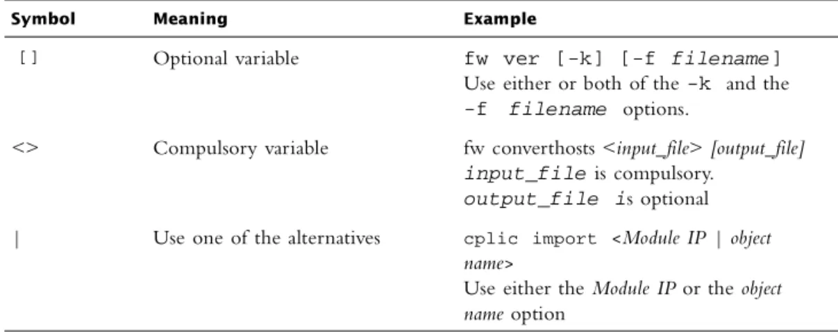
SYN Attack
FIGURE 1-12TCP page
Specify which of the attacks to defend against by checking the check box next to the attack’s name in the tree.
SYN Attack
For a detailed description of SYN attacks and SYNDefender, see “SYN Attacks and SYNDefender” on page 58.
TCP
FIGURE 1-13SYN Attack.
Override module’s SYNDefender configuration — Select this option to specify that the settings on this page override the SYNDefender settings specified for individual Modules.
SYN attack defense can be specified in two ways:
• on a per-Module basis
• in the SmartDefense SYN Attack page (FIGURE 1-13)
Activate SYN Attack protection — If Override module’s SYNDefender configuration is checked, then you can activate protection for all Modules. Click Configure to specify the parameters of the protection method in the SYN Attack window (FIGURE 1-14).
Early Versions SYNDefender configuration — Check this option to open the window (FIGURE 1-15) to configure SYNDefender protection for earlier version Modules.
SYN Attack
SYN Attack window (All Modules) FIGURE 1-14SYN Attack window
Track — Select the action to take if an attack is detected.
Track Level — Select one of the following:
• Attacks only — The action specified under Track will be taken only when an attack is detected and when it is over.
• Individual SYNs — The action specified under Track will be taken for each SYN packet.
Timeout — Specifies how long SmartDefense waits for an acknowledgment before concluding that the connection is a SYN attack.
Attack threshold — If more than Attack threshold unacknowledged SYN packets are detected at any one time, then SmartDefense will conclude that a SYN attack is taking place.
Protect external interface only — Protect against SYN attacks only on the external interface.
TCP
SYN Attack window (Earlier Versions) FIGURE 1-15SYN Attack window
Method — Choose one of the following:
• None — SYNDefender is not deployed.
If you choose this option, your network will not be protected from SYN attacks.
• SYN Gateway — Deploy the SYN Gateway method.
• Passive SYN Gateway — Deploy the Passive SYN Gateway method.
Timeout — Specifies how long SYNDefender waits for an acknowledgment before
concluding that the connection is a SYN attack.
Maximum Sessions — Specifies the maximum number of protected sessions.
This parameter is relevant only if Passive SYN Gateway is selected under Method. If
SYN Relay is selected, all sessions are protected.
This parameter specifies the number of entries in an internal connection table maintained by SYNDefender. If the table is full, SYNDefender will not examine new connections.
Display Warning Messages — If set, SYNDefender will print console messages regarding its status.
Small PMTU
When a connection between two hosts is established, the sides involved exchange their TCP maximum segment size (MSS) values. The smaller of the two MSS values is used for the connection. The MSS for a system is usually the MTU (Maximum Transfer Unit) at the link layer minus 40 bytes for the IP and TCP headers.
Small PMTU
When TCP segments are destined to a non-local network, the Don’t Fragment bit is set
in the IP header. Any router or media along the path may have an MTU that differs from that of the two hosts. If a media is encountered with an MTU that is too small for the IP datagram being routed, the router will attempt to fragment the datagram accordingly. Upon attempting to do so, it will find that the Don’t Fragment bit in the IP
header is set. At this point, the router should inform the sending host with an ICMP destination unreachable message that the datagram cannot be forwarded further without fragmentation.
When a network router receives a packet larger than the Maximum Transfer Unit (MTU) of the next network segment, and that packet’s IP layer Don’t Fragment bit is flagged, the router should send an ICMP destination unreachable message back to the sending host. When this does not happen, packets can be dropped, causing a variety of errors that will vary with the application that is communicating over the failed link.
FIGURE 1-16Small PMTU page
TCP
Minimal MTU size — Define the minimal allowed MTU. An exceedingly small value
will not prevent an attack, while an unnecessarily large value might result in legitimate requests to be dropped, causing “black hole” effects and degrading performance.
Sequence Verifier
The Sequence Verifier matches the current TCP packet’s sequence numbers against a state kept for that TCP connection. Packets that match the connection in terms of TCP session, but have sequence numbers that do not make sense, are either dropped, or stripped of data.
FIGURE 1-17Sequence Verifier page
Track — Select the appropriate tracking option.
Track on — Specify the type of out of state packets to be tracked, as follows:
anomalous — Track only packets that do not normally appear in legitimate connections.
Sequence Verifier
suspicious — Track only packets seemingly erroneous packets, unrelated to the
connection.
DNS
FIGURE 1-18DNS page
UDP protocol enforcement — If selected, VPN-1/FireWall-1 monitors DNS traffic to ensure compliance with RFC 1035, that is, that the DNS packets are correctly formatted. This feature does not support DNS over TCP (TCP Zone Transfer).
FTP
FTP
FTP Bounce Attack
FTP Bounce Attack
FIGURE 1-20FTP Bounce pageFTP
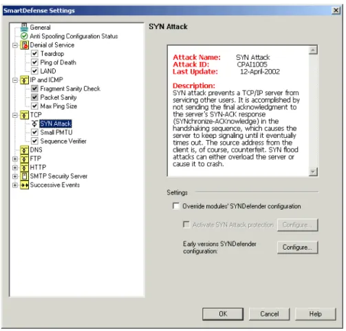
FTP Security Server
FIGURE 1-21FTP Security ServerConfigurations apply to all connections — The FTP Security Server is invoked for all connections.
Configurations apply only to connections related to resources used in the Rule Base —
The FTP Security Server is invoked when a rule specifies an FTP Resource and/or User Authentication is defined.
FTP Security Server
FTP Security Server — Allowed FTP Commands FIGURE 1-22FTP Security Server — Allowed FTP Commands
FTP
FTP Security Server
FTP Security Server — Prevent Known Ports Checking FIGURE 1-24FTP Security Server — Prevent Known Ports Checking
FTP
FTP Security Server — Prevent Port Overflow Checking FIGURE 1-25FTP Security Server — Prevent Port Overflow Checking
FTP Security Server
Prevent Port Overflow Checking
HTTP
HTTP
General HTTP Worm Catcher
General HTTP Worm Catcher
FIGURE 1-28HTTP — General HTTP Worm Catcher page
You can import updates from the Check Point Web site or add patterns manually into the Worm Patterns list.
HTTP
HTTP Security Server
FIGURE 1-29HTTP Security Server page
Configurations apply to all connections — The HTTP Security Server is invoked for all connections.
Configurations apply only to connections related to resources used in the Rule Base —
The HTTP Security Server is invoked when a rule specifies an HTTP Resource and/or User Authentication is defined.
HTTP Security Server
HTTP Security Server — HTTP Format Sizes FIGURE 1-30HTTP Security Server — HTTP Format Sizes page
HTTP
HTTP Security Server — ASCII Only Request Headers FIGURE 1-31HTTP Security Server — ASCII Only Request Head ers page
HTTP Security Server
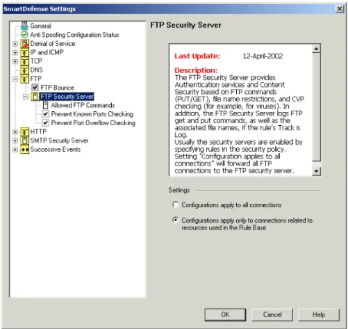
HTTP Security Server — ASCII Only Response Headers FIGURE 1-32HTTP Security Server — ASCII Only Response Head ers page
Maximum URL length — Prevents the security server from getting unwanted data by limiting the length of the URL in HTTP client request or in redirect requests.
Maximum HTTP header length — Prevents the security server from getting unwanted data by limiting the maximum header length the security server will get both in the HTTP client request and in the HTTP server reply.
Maximum number of HTTP headers — Prevents the security server from getting unwanted data by limiting the number of headers the security server will get both in the HTTP client request and in the HTTP server reply.
In addition, all HTTP headers are by default forced to be ASCII only. This will prevent some malicious content from passing in the HTTP protocol headers.
SMTP Security Server
SMTP Security Server
FIGURE 1-33SMTP Security Server page
Configurations apply to all connections — The SMTP Security Server is invoked for all connections.
The settings in the Mail and Recipient Content window (FIGURE 1-35 on page 50) apply only if an SMTP Resource is defined, even if Configurations apply to all connections is checked.
Configurations apply only to connections related to resources used in the Rule Base — The SMTP Security Server is invoked when a rule specifies an SMTP Resource and/or User Authentication is defined.
SMTP Content
SMTP Content
FIGURE 1-34SMTP Security Server — SMTP Content
The SMTP Security Server provides Content Security that enables a Security Administrator to:
• provide mail address translation by hiding outgoing mail’s From address behind a standard generic address that conceals internal network structure and real internal users
• perform mail filtering based on SMTP addresses and IP addresses
• strip MIME attachments of specified types from mail
• strip the Received information from outgoing mail, in order to conceal internal network structure
• drop mail messages above a given size
• send many mail messages per single connection
• resolve the DNS address for mail recipients and their domain on outgoing connections (MX Resolving)
SMTP Security Server
• control the number of connections per site
• control the overall connections generated by the mail dequeuer
• provide a Rule Base match on the Security Server mail dequeuer which enables:
• a mail-user based policy
• better performance of different mail contents action per recipient of a given
• generation of different mail contents on a per-user basis
• application of content security features at the user level
• perform CVP checking (for example, for viruses)
Mail and Recipient Content
Mail and Recipient Content
Allow multiple content-type headers — If checked, the SMTP Server will allow multiple content-type headers.
Allow multiple “encoding” headers — If checked, the SMTP Server will allow multiple “encoding” headers.
Allow non-plain “encoding” headers — If checked, the SMTP Server will allow non-plain “encoding” headers.
Allow unknown encoding — If checked, the SMTP Server will allow unknown encoding methods.
Force recipient to have a domain name — If checked, the SMTP Server will force the recipient to have a domain name.
Perform aggressive MIME strip — This property controls two different levels of performing the MIME strip:
• if checked, the entire mail body will be scanned for headers such as “Content-Type: text/html; charset=utf-8” and the MIME strip will be performed accordingly
• if unchecked, only the mail headers section and the headers of each MIME part will be scanned. If a relevant header is located, the MIME strip will be
performed accordingly.
Note - The settings is this window apply only if an SMTP Resource is defined, even if Configurations apply to all conenctions in the SMTP Security Server window (FIGURE 1-33 on page 48) is checked.
Successive Events
Successive Events
FIGURE 1-36Successive Events page
VPN-1/FireWall-1’s Successive Events feature (formerly known as Malicious Activity Detection) provides a mechanism for detecting malicious or suspicious events and notifying the system administrator. This feature is implemented by reading the VPN-1/FireWall-1 Log File and matching Log entries to attack profiles. The VPN-1/FireWall-1 administrator can modify attack detection parameters, turn
detection on or off for specific attacks, or disable the Successive Events feature entirely. The feature runs on the SmartCenter Server and analyses logs from VPN/FireWall Modules. Logs which do not reach the SmartCenter Server (for example, local logs and logs sent to Log Server) are not analyzed by the Successive Events.
SmartDefense provides a mechanism for detecting malicious or suspicious events and notifying the system administrator. The mechanism allows you sending alerts when different successive malicious events are detected.
Address Spoofing
Max memory allocation size — Specify the amount of memory allocated to the
detecting mechanism (in Kbytes). If more memory is required, the feature will exit. Memory requirements can be reduced by reducing the number of attacks or decreasing the value of the Reset accumulated events property.
Reset accumulated events every...sec — Define the period upon expiration of which
events will be deleted from SmartDefense’s internal tables. High values reduce CPU usage but increase memory requirements.
Logging attempts interval — The interval (in seconds) over which log entries corresponding to this attack are counted. A large resolution value reduces memory usage but increases the probability that attacks will not be recognized.
Max logging attempts — The number of times an event must occur within the Logging attempts interval in order for an error notification to be sent.
Address Spoofing
FIGURE 1-37Successive Events — Address Spoofing page
Successive Events
To configure when the tracking option specified under Action will be taken, click Advanced to display the Advanced Configuration window (FIGURE 1-38).
FIGURE 1-38Successive Events — Advanced Configuration window
Resolution —
Time Interval — Attempts number —
Port Scanning
Port Scanning
FIGURE 1-39Successive Events — Port Scanning page
Action — Select the appropriate tracking option.
To configure when the tracking option specified under Action will be taken, click
Successive Events
Local Interface Spoofing
FIGURE 1-40Successive Events — Local Interface Spoofing page
Action — Select the appropriate tracking option.
To configure when the tracking option specified under Action will be taken, click Advanced to display the Advanced Configuration window (FIGURE 1-38 on page 54).
Successive Alerts
Successive Alerts
FIGURE 1-41Successive Events — Successive Alerts page
Action — Select the appropriate tracking option.
To configure when the tracking option specified under Action will be taken, click Advanced to display the Advanced Configuration window (FIGURE 1-38 on page 54).
SYN Attacks and SYNDefender
Successive Multiple Connections
FIGURE 1-42Successive Events — Successive Multiple Connections page
Action — Select the appropriate tracking option.
To configure when the tracking option specified under Action will be taken, click Advanced to display the Advanced Configuration window (FIGURE 1-38 on page 54).
SYN Attacks and SYNDefender
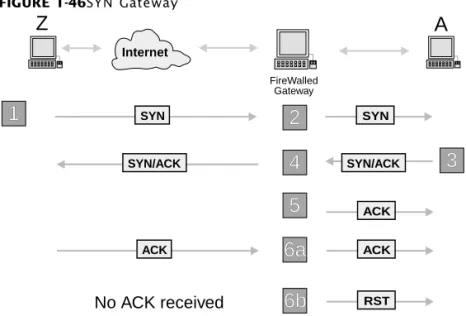
The TCP Three-Way Handshake
TCP (Transport Control Protocol) is a connection-oriented, reliable transport protocol. Two participating hosts must first establish a connection by a three-way handshake between them. TCP assigns sequence numbers to every byte in every segment and acknowledges all data bytes received from the other end.
Successive Multiple Connections
For example, if host A wants to establish a connection with host B, A begins by sending a SYN packet (a TCP packet with the SYN bit set) to B. B replies with a SYN/ACK packet (a TCP packet with the SYN and ACK bits set). A completes the three-way hand-shake with a TCP ACK packet.
FIGURE 1-43TCP SYN handshake
When B receives the SYN packet, it allocates substantial memory for the new connection. If there were no limit to the number of connections, a busy host would quickly exhaust all of its memory trying to process TCP connections. However, there is usually a small upper limit to the number of concurrent TCP connection requests (“backlog queue”) a given application can have running on the host.
There is an upper limit for each server program (depending on the configuration) of outstanding unacknowledged (un-ACK’d) connection requests. When the backlog queue limit is reached, an attempt to establish another connection will fail until one of the backlogged connection either becomes established (SYN/ACK packet is ACK’d), is reset (a RST packet is received) or times out.
How the Attack Works
A client initiates a TCP connection by a request with the SYN flag set in the TCP header. Normally the server replies with a SYN/ACK identified by the source IP address in the IP header. The client then sends an ACK to the server (FIGURE 1-43 on page 59) and data exchange begins.
When the source IP address is spoofed (changed) to that of an unreachable host, the targeted TCP cannot complete the three-way hand-shake and will keep trying until it times out. This is the basis for the SYN flood attack.
The attacking host (Z) sends a small number (less than 10 is sufficient) of SYN requests to the target TCP port (for example, the Web server). The attacking host also spoofs the source IP address as that of another (Z’), currently unreachable host. The process is depicted in FIGURE 1-44.
Internet
A
SYN SYN/ACK
ACK
SYN Attacks and SYNDefender
FIGURE 1-44SYN Attack
The source IP address (Z’) must be unreachable because the attacker does not want any host to receive the SYN/ACKs from the target TCP, which would elicit a RST from that host (an RST packet is issued when the receiving host does not know what to do with a packet) and thus foil the attack (FIGURE 1-45).
FIGURE 1-45The SYN Attack unsuccessful, because Z’ is reachable
Instead, until the SYN requests time out, A will not accept any connection requests. If the attacks were, for example, against A’s Web server, then that Web server will be inaccessible for some two minutes as a result of an attack that lasted less than one second.
Internet
These packets are sent by Z but "spoofed" so that they seem to come from
Z' - an IP address
unreachable
A replies to Z'
Z
Z'
Z'
Z'
Z'
Z'
Z'
Z'
Z'
Z'
SYN SYN SYN SYN SYN SYN SYN SYN/ACK SYN/ACKA
2
1
InternetA replies to Z' Z Z' Z' Z' Z' Z' Z' Z' Z' Z' Z' Z' SYN SYN SYN SYN SYN SYN SYN RST RST SYN/ACK SYN/ACK A These packets are sent by Z but "spoofed" so that they seem to come from
Z' - a IP address
reachable
1
2
Z' resets the connection and
the attack is unsuccesful
Successive Multiple Connections
VPN-1/FireWall-1 SYNDefender
Check Point’s SYNDefender provides three different approaches for defending against a SYN flooding attack:
• SYN Gateway (supported only for pre-NG VPN/FireWall Modules) • Passive SYN Gateway
• SYN Relay (not supported for pre-NG VPN/FireWall Modules)
All these solutions are integrated into the VPN/FireWall Module, which intercepts all packets before they are observed by the operating system and performs Stateful Inspection on these packets. The system administrator can choose which of the solutions is best suited to a particular environment.
SYN Gateway
In order for the resetting of SYN connection attempts to be effective against the SYN flooding attack, the reset timer must be short enough to keep A’s backlog queue from filling up, while at the same time long enough to enable users coming over slow links to connect. The SYN Gateway solution counters the attack by ensuring that an ACK packet is sent in immediate response to A’s SYN/ACK packet.
When A receives the ACK packet, the connection is moved out of the backlog queue and becomes an open connection on A. Internet servers can typically handle hundreds or thousands of open connections, so the SYN flooding attack is no more effective in creating a denial of service condition than a hacker trying to establish an excessive number of valid connections to the server. The backlog queue is effectively kept clear and it is possible to wait longer before resetting connections which have not been completed.
SYN Attacks and SYNDefender
FIGURE 1-46SYN Gateway
1 VPN-1/FireWall-1 intercepts a SYN packet going to host A and records the event in an INPSPECT state table.
2 VPN-1/FireWall-1 lets the SYN packet continue on to A.
3 VPN-1/FireWall-1 intercept A’s SYN/ACK reply to Z and correlates with the corresponding SYN packet sent by Z.
4 VPN-1/FireWall-1 lets the SYN/ACK continue on its way to Z.
5 VPN-1/FireWall-1 sends an ACK packet to A, which moves the connection out of A’s backlog queue.
6 At this point, one of two things will happen, depending on whether the connection attempt is valid.
a If Z’s connection attempt is valid, then VPN-1/FireWall-1 will receive an ACK from Z which it will pass on to A.
A ignores this second redundant ACK since the three-way handshake has already been completed.
b If Z’s IP address does not exist, then no ACK packet will return from Z to A and the reset timer will expire. At this point, VPN-1/FireWall-1 resets the connection.
The effectiveness of the SYN Gateway solution is based on quickly moving connection attempts out of the backlog queue. SYN flood connection attempts then fail to fill up
Internet
Z
SYN SYN ACK ACK RST ACK SYN/ACK SYN/ACKA
5
4
6a
6b
3
2
1
FireWalled GatewaySuccessive Multiple Connections
Passive SYN Gateway
Passive SYN Gateway is similar to SYN Gateway, except that VPN-1/FireWall-1 does not simulate Z’s ACK packet to A, and instead waits for Z’s ACK before passing it on to A.
The unacknowledged connection remains in A’s backlog queue, but times out after VPN-1/FireWall-1’s timeout period, which is much shorter than the backlog queue’s timeout period.
FIGURE 1-47 depicts Passive SYN Gateway.
FIGURE 1-47Passive SYN Gateway
SYN Relay
The SYN flooding attack sends SYN packets with the source addresses of unreachable hosts which will not reply to SYN/ACK packets. SYN Relay counters the attack by making sure that the three way handshake is completed (that is, that the connection is a valid one) before sending a SYN packet to the connection’s destination (A). SYN Relay is a high-performance kernel-level process which acts as a relay mechanism at the connection level. FIGURE 1-48 depicts SYN Relay.
SYN SYN
ACK
RST ACK
SYN/ACK
4
SYN/ACK5a
5b
3
2
1
No ACK received
Internet
Z
A
FireWalled Gateway
SYN Attacks and SYNDefender
FIGURE 1-48SYN Relay
1 VPN-1/FireWall-1 intercepts a SYN packet going to host A.
2 VPN-1/FireWall-1 does not pass the SYN packet to A, but rather acts on A’s behalf and replies with a SYN/ACK packet to Z.
3 If an ACK packet is received from Z, then ...
• VPN-1/FireWall-1 sends a SYN packet to A.
• A replies with a SYN/ACK packet.
• VPN-1/FireWall-1 replies with an ACK packet.
At this point the connection from Z to A is established and VPN-1/FireWall-1 is able to begin passing packets between Z and A. SYNDefender correctly translates the connection sequence numbers, which are now different for each half of the connection.
If VPN-1/FireWall-1 does not receive a packet for several seconds during any of the above steps, or if it receives a RST when an ACK or SYN/ACK are expected, it terminates the connection immediately.
Note that if Z contacts an unavailable server on A, it will first connect and then get a RST, which is not normal but harmless.
Guidelines for Deploying SYNDefender
While there are no strict rules for when to use each of the SYNDefender solutions, some basic guidelines will help establish the appropriate policy for a given situation.
Passive SYN Gateway
SYN SYN ACK ACK SYN/ACK SYN/ACK
5
4
6
3
2
1
InternetZ
A
FireWalled GatewayGuidelines for Deploying SYNDefender
• Users establishing valid connections with the protected server will not incur any
delay in connection setup time.
• There is very little overhead on VPN-1/FireWall-1.
SYN Relay
SYN Relay’s primary advantage is that the protected server does not receive any invalid connection attempts. If the server has limited memory or often reaches an overloaded state, then SYN Relay’s complete filtering of invalid connection attempts can be advantageous in case of attack. Users making valid connections to the server may experience slightly longer connection setup time than with SYN Gateway.
SYN Gateway
Since connections are established on the server, that is, moved from the backlog queue, it is important to consider how many established connections the protected server can support relative to the normal load handled by the server.
It is not possible to specify SYN Gateway for individual VPN/FireWall Modules. SYN Gateway is supported only for pre-NG VPN/FireWall Modules.
Choosing an Appropriate SYNDefender Method
Following are some recommendations for choosing the SYNDefender method to deploy.
1) If you are not currently under SYN attack, then consider whether you need SYNDefender at all. Since the SYN flooding attack is a denial of service attack rather than a security breach, it may be more effective to deploy SYNDefender only after a SYN attack actually occurs.
2) To be notified if and when you do come under attack, use Passive SYN Gateway with Maximum protected sessions set to 50 or less.
Note - SYN Relay is not supported for pre-NG VPN/FireWall Modules.
SYN Attacks and SYNDefender
Setting the timeout can be a delicate issue. If the timeout is too short, legitimate connections may fail; if it is too long, some attacks may succeed. It is therefore recommended that Passive SYN Gateway be used primarily as a monitoring tool (in conjunction with the Log Viewer) to identify attacks.
3) If SYN attacks are a real concern, then SYN Relay should be used. SYN Relay provides complete protection from a SYN attack, at the cost of increased memory usage. There may also be a (usually) undetectable delay in connection setup. 4) It is recommended that SYN Gateway not be used.
C H A P T E R
2
Network Address
Translation (NAT)
In This Chapter
Introduction
The Need for Address Translation
The need for IP address translation — replacing one IP address in a packet by another IP address — arises in two cases:
1) The network administrator wishes to conceal the network’s internal IP addresses from the Internet.
Introduction page 67
Configuring Network Address Translation page 70
Address Translation Modes page 70
Address Translation and Routing page 78
IANA Recommendations page 86
Supported Services page 86
Generating Address Translation Rules Automatically page 87
Network Address Translation Rule Base page 89
Address Translation Examples page 102
Advanced Topics page 112
Introduction
The administrator may reason that there is nothing to be gained, from a security point of view, by making a network’s internal addresses public knowledge.
2) An internal network’s IP addresses are invalid Internet addresses (that is, as far as the Internet is concerned, these addresses belong to another network).
This situation may have arisen for historical reasons: an internal network was originally not connected to the Internet and its IP addresses were chosen without regard to Internet conventions. If such a network is then connected to the Internet, its long-established internal IP addresses cannot be used externally. Changing these addresses may be impractical or unfeasible.
In both cases, the internal IP addresses cannot be used on the Internet. However, Internet access must still be provided for the internal hosts with the invalid or secret IP addresses.
Application gateways (proxies) have historically served as a partial solution to these problems. For example, to hide his or her internal IP addresses, a user can TELNET to a gateway and from there continue to the Internet through a proxy. VPN-1/FireWall-1 can be easily set up to provide and enforce such a scheme for a wide variety of services (FTP, TELNET, HTTP, and almost all other TCP, UDP and RPC services). Moreover, VPN-1/FireWall-1 supplements this scheme by providing user authentication on the gateway.
On the other hand, proxies have drawbacks:
• Proxies are tailored per application, so it is impossible to use applications that are not proxied, inbound or outbound.
• Proxies are not transparent, so that even authorized outbound users need to go
through the application on the gateway, and impose a large overhead on the gateway host. Once a connection is accepted by a proxy, it functions as a packet forwarder at the application layer, which is an inefficient use of resources.
• It is difficult to provide good proxies for protocols other than TCP.
In contrast, VPN-1/FireWall-1’s generic and transparent fully RFC 1631 compliant Address Translation feature provides a complete and efficient solution. The
administrator can determine which internal addresses are to be hidden (that is, mapped to the FireWalled host’s IP address) and which are to be mapped to a range of IP addresses visible to the Internet. At the same time, internal hosts can be configured to be accessible from the Internet even though their internal IP addresses are invalid Internet addresses. VPN-1/FireWall-1 achieves full Internet connectivity for internal clients.
Example
Address Translation can be used to implement “one way routing,” so that there is no route from the outside to an internal network or to hosts.
Example
Consider the following network configuration:
FIGURE 2-1Example Network Configuration
Suppose the administrator of this network wishes to provide mail services to the internal (private) hosts, but the internal IP addresses cannot be used, for one of the reasons stated above (see “The Need for Address Translation” on page 67.)
One possible solution is to move the mail server (which is currently on one of the internal hosts) to the gateway. This solution is not optimal, because of:
• the significant overhead the mail server imposes on the gateway • reduced security
• the administrative overhead incurred when modifying the configuration
A better solution might be to implement Address Translation on the gateway, as follows, using the Static Destination Mode of Address Translation (see “Static Destination Mode” on page 77):
• The mail server is assigned a valid IP address (its public IP address), which is exposed to the Internet. However, internally, the mail server retains its existing (private) IP address.
• Incoming mail arrives at the gateway, where the destination IP address (the mail server’s public IP address) is translated to its private address. The source IP address of outgoing mail is translated from the mail server’s private IP address to its public IP address.
Note - Address Translation changes IP addresses in the packet, so it is almost always necessary to make some changes in the routing tables to ensure that packets with translated addresses reach their proper destinations.
mailsrvr London Router FireWalled Gateway localnet private public Internet
Configuring Network Address Translation
Routing tables on the gateway and router may have to be modified to implement this scheme (see “Address Translation and Routing” on page 78).
Configuring Network Address Translation
To configure Network Address Translation (NAT), proceed as follows:
1 Determine which NAT Mode to use: Hide Mode or Static Mode.
See “Address Translation Modes” on page 70 for detailed information about these modes.
2 Define the NAT Rule Base.
There are two methods of defining NAT rules: automatic (the recommended method) and manual.
• Automatic Definition — The NAT rules are automatically generated, based on
the properties of network objects (gateways, hosts, networks and Address Ranges).
The object’s properties are applied whenever the object is used in the Security Policy. In addition, numerous implementation details are automatically handled correctly (for example, Anti-Spoofing). In contrast, when rules are defined manually, these implementation details must be implemented manually as well.
Automatic definition is the simplest method to use, but it is inflexible: the generated rules cannot be modified, but you can add rules (with the second method — see below) before and after the automatically generated rules. For information on this method, see “Generating Address Translation Rules Automatically” on page 87.
• Manual Definition
The NAT Rule Base is defined manually. You can also add NAT rules before and after the rules generated automatically by the previous method, but you cannot modify or delete the automatically generated rules.
This method is not as simple to use as the previous method, but is more powerful and more flexible.
3 Configure routing so that NAT packets are properly routed.
See “Address Translation and Routing” on page 78 for more information.
Hide Mode
Dynamic (Hide)—Many invalid addresses are translated to a single valid address, and
dynamically assigned port numbers are used to distinguish between the invalid addresses.
Dynamic Address Translation is called Hide Mode, because the invalid addresses are “hidden” behind the valid address. For details of this mode, see “Hide Mode” on page 71.
Static—Each invalid address is translated to a corresponding valid address. There are two modes of Static Address Translation:
• Static Source Mode (see “Static Source Mode” on page 75)
• Static Destination Mode (see “Static Destination Mode” on page 77)
In This Section
Hide Mode
Hide Mode is used for connections initiated by hosts in an internal network, where the hosts’ IP addresses are invalid. In Hide Mode, the invalid internal addresses are hidden behind a single valid external address. Different connections are distinguished from each other using both:
• dynamically assigned port numbers, and • the destination IP address
Distinguishing Between Connections
For each destination IP address, source port numbers are dynamically assigned from two pools of numbers:
• from 600 to 1023 (low ports)
Hide Mode page 71
Static Source Mode page 75
Static Destination Mode page 77
Warning - The IP address of a gateway’s external interface must never be hidden.
Address Translation Modes
• from 10,000 to 60,000 (high ports)
If the original source port number is less than 1024, then a port number is assigned from the first pool. If the original port number is greater than 1024, then a source port number is assigned from the second pool. VPN-1/FireWall-1 keeps track of the source port numbers assigned, so that the original source port number is correctly restored for return packets. A port number currently in use is not assigned again to a new
connection.
The total number of connections that can be hidden is more than 50,000 for each destination IP address.
Limitations
Hide Mode has several limitations:
• Hide Mode does not allow access to the “hidden” hosts to be initiated from the outside, that is, an external machine cannot connect to any of the hosts whose addresses have been translated. For example, in the configuration in FIGURE 2-3 on page 73, if you run your HTTP server on 200.0.0.108 (one of the internal machines with an invalid address), external machines will not be able to connect to your HTTP server using 199.100.145.35 (the gateway’s valid address) as the destination.
This limitation can also be considered an advantage of Hide Mode.
• Hide Mode cannot be used for protocols where the source port number cannot be changed.
• Hide Mode cannot be used when the external server must distinguish between
clients on the basis of their IP addresses, since all clients share the same IP address under Hide Mode.
Example
Suppose localnet is an internal network with invalid addresses are as follows:
199.100.145.35 is the address of gateway’s external interface.
You can hide the invalid addresses behind the valid address by specifying Address Translation in the NAT tab of localnet’s Network Properties window as follows:
Valid IP address Invalid IP addresses
Hide Mode
FIGURE 2-2NAT tab for localnet
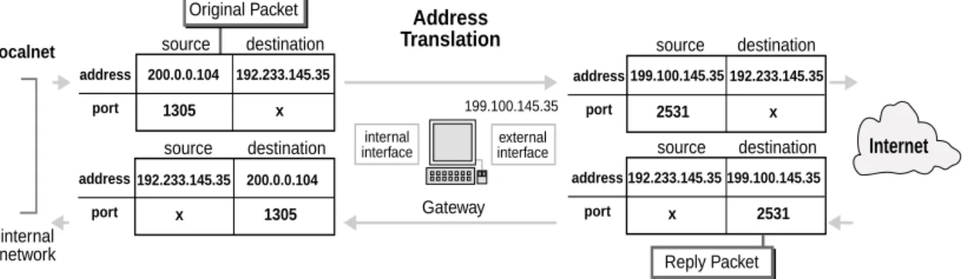
Source addresses of outbound packets from hosts in localnet will be translated to 199.100.145.35, as illustrated in FIGURE 2-3. The source port number serves to direct reply packets to the correct host.
FIGURE 2-3Hide Mode Address Translation
In FIGURE 2-4, the first rule must be manually inserted, and the second rule is automatically generated from the above definition (FIGURE 2-2 on page 73):
Original Packet Gateway internal network localnet Internet Address Translation address port source destination 200.0.0.104 192.233.145.35 1305 x address port source destination 192.233.145.35 199.100.145.35 199.100.145.35 199.100.145.35 2531 x address port source destination 200.0.0.104 192.233.145.35 1305 x address port internal
interface source destination
192.233.145.35 2531 x Reply Packet external interface