Land Instruments International Dronfield, S18 1DJ
England
Telephone: (01246) 417691 Facsimile: (01246) 410585 Email: [email protected] Internet: www.landinst.com
© Land Instruments International, 2004 Publication Nº: LSCB198.298 Issue: First 11/04 Land Instruments International 10 Friends Lane
Newtown PA 18940-1804 U.S.A. Telephone: (215) 504 8000 Facsimile: (215) 504 0879 Email: [email protected] Internet: www.landinstruments.net
User Guide
Quality Assurance 198.298
All packaging material used for this product is 100% recyclable.
This product complies with current European directives relating to electromagnetic compatibility and safety (EMC directive 89/336/EEC; Low voltage directive 73/23/EEC).
abcdefg
ABC
The Quality Management System of Land Instruments International Ltd. is approved to BS EN ISO9001:2000 for the design and manufacture, stockholding, in-house repair and site servicing of non contact temperature measuring instrumentation. Associated software designed and developed in accordance with TickIT.
Calibration certificates are available from our UKAS accredited Calibration Laboratory No. 0034. The Land calibration laboratory complies with the requirements of the international standard BS EN/IEC 17025.
Safety Information 198.298 SAFETY INFORMATION
SYMBOL PUBLICATION DESCRIPTION
3
IEC 417, No.5031 CurrentDirect
IEC 417, No.5032 Alternating
Current
IEC 417, No.5033 Both direct and alternating current
IEC 617-2, No.02-02-06 Three-phase alternating Current
IEC 417, No.5017 Earth
(ground) term inal
IEC 417, No.5019 Protective conductor terminal
IEC 417, No.5020 Fram e or chassis term inal
IEC 417, No.5021 Equipotentiality
IEC 417, No.5007 On (supply)
IEC 417, No.5008 Off (supply)
IEC 417, No.5172 Equipm ent protected throughout by double insulation or reinforced insulation (equivalent to Class
Safety Information 198.298
SYMBOL PUBLICATION DESCRIPTION
ISO 3864, No. B.3.6
Caution ISO 3864, No. B.3.1
WARNING Risk of electric shock
BS EN 100015 Observe precautions for
handling electrostatic discharge sensitive devices
Refer to the operating instructions BS EN 60825-1
WARNING Laser Radiation
Note
Contents 198.298
CONTENTS
QUALITY ASSURANCE
SAFETY INFORMATION
CONTENTS (This Page)
PREFACE
1.0 INTRODUCTION 1
2.0 SYSTEM OVERVIEW 2
2.1 Landscan Control Batch Processor 2.2 Configuration Software
3.0 PROCESSOR HARDWARE INSTALLATION 4
3.1 Landscan Control Batch Processor Dimensions
4.0 SYSTEM CABLE CONNECTIONS 5
4.1 Landscan Control Batch Processor Front Panel 4.2 Landscan Control Batch Processor Rear Panel 4.3 Mains Power
4.4 Encoder Input (X1) 4.5 Encoder I/O (X2)
4.6 External Communications - Ethernet (2-off) (X6/X7) 4.7 External Communications - Serial RS232C (X9) 4.8 System Alarm (X10)
4.9 Remote Laser Control Input (X11) 4.10 Scan Valid Retransmit (X12)
4.11 LSP/LS Linescanning Thermometer Connection (X13) 4.12 Digital/Analog Input/Output Cards (X14/X15/X16) 4.13 RS232C Terminal Connector (Front Panel)
5.0 SYSTEM DISPLAY 15
5.1 System Display LED's
Contents 198.298 CONTENTS (Continued)
7.0 QUICK-START GUIDE 17
7.1 Select the Ethernet ID Setting 7.2 Applying Power to the Processor 7.3 Display System Status
7.4 Connection of the Processor to the Personal / Laptop Computer 7.5 Communicating with the Processor
7.6 Temperature Data Capture
8.0 ROTARY MACHINE APPLICATIONS 21
8.1 Overview
8.2 Installation of Hardware 8.3 Software
9.0 ACCESSORIES 22
10.0 MAINTENANCE 23
Preface 198.298
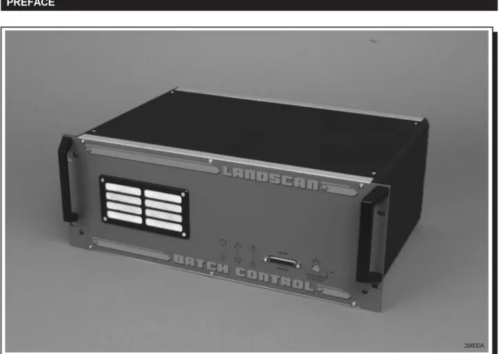
PREFACE
Fig. A - Landscan Control Batch (LSC-B) Processor
These instructions should be used in conjunction with the information detailed within the Landscan Control Batch (LSC-B) Processor Installation Guide.
Any instructions undertaken must be carried out by suitably trained personnel.
Page 1 198.298
1.0 INTRODUCTION
This User Guide provides a system overview describing the hardware installation and introduces the processor Configuration Software, utilised for interrogation, setup and modification of the system's operating parameters. A more comprehensive User Guide accompanies the Configuration Software which describes the configuration of the software in detail and provides information about the processing operations.
The Landscan Control Batch processor can be used with Landscan LSP series or Landscan LS series equipment, the selection of a system determined by the setting of jumper links on the X13 PCB.
Page 2 198.298
Fig. 1 - Typical Landscan Control Batch System Overview
2.0 SYSTEM OVERVIEW
The Landscan Control Batch Processor provides a dedicated data input, mathematical processing facility for use with Landscan sensor heads for process control applications.
The processor provides external communications interfaces for system configuration and for the transmission of scan line information to host computers. This can be achieved using RS232C or an Ethernet connection when the transmission of large quantities of data at high speed is required. In addition, the Landscan Control Batch Processor provides optional digital and analogue I/O, allowing the processor to perform process monitoring and control. The processor has been designed to function automatically and continuously with in-built self-analysis of system events, plus comprehensive diagnostic information accessible through the configuration software and front panel display.
The processor supports up to four simultaneous Ethernet connections.
In addition, the processor captures data from any of the Landscan heads and manipulates the information into a 2-dimensional analysis grid.
The system can be considered to consist of two distinct components, the Control Batch Processor and the Configuration Software which runs on a portable PC and is used to configure the processor parameters.
298001
1 23
45
LSP SYSTEM
LSP Linescanning Thermometer
Landscan Control Batch Processor Ethernet Ethernet PROCESS CONTROL PROCESS MONITORING Landscan WCA Optional Software RS232 Serial Comms
Interconnection Cable Portable PC
Temporary Link RS232
Configuration Software X XX.XX X.XX X.XX
RS 23 2
Page 3 198.298
2.1 Landscan Control Batch Processor
2.2 Configuration Software
The Landscan Control Batch Processor is a rackmounted unit, that will sample 1000 data points per scan line, at scan speeds between 10Hz and 100Hz.
The processor can partition the previous product temperature data into up to 500 analysis fields. Within each of these fields, processing functions are applied including min, mean, max and standard deviation.
An analog 4 to 20mA output is provided that allows for remote control of the Landscan sensor head's emissivity settings. An additional alarm relay output is available to alert the user to conditions which may result in the data captured being invalid. (e.g. power loss at the Landscan sensor head)
The product edges can be detected by identifying where in the scan line the temperature rises above a preset threshold level. This is achieved automatically by analysing the peak product temperature in relation to the environmental background temperature. The system uses the edge detection information to align the field positions, allowing the fields to track a target which may be moving erratically within the sensor’s field of view. If the target moves, grows or shrinks within the sensor’s field of view, the fields follow these movements. Optional analogue and digital I/O can be used to provide process monitoring and control.
The processor provides an RS232 serial communication connection located on the front panel, which allows a laptop personal computer or similar to be connected temporarily to allow modifications to the system configuration. A second RS232 serial communications connection can be used for permanent monitoring. Ethernet communication is also provided on the processor to allow the connection of third party computer systems and also the Landscan WCA software. Calibrated temperature data and zone processed data are available in real time for the purposes of analysis and database storage by remote computer systems.
Configuration of the processor is fully supported by the Ethernet and RS232C communications, with the configuration software capable of setting up the processor for an appropriate network setting.
When the user has satisfactorily configured the system for a particular application, the parameters essential for operation are secured against power loss inside the system. The processor will continuously operate without interruption, utilising these settings until parameter changes are requested by the user.
The Configuration Software enables the user to communicate with the processor for initial setting up of the operating parameters and provides limited process monitoring capability. All operating parameters are securely retained in the non-volatile memory of the processor.
The Configuration Software features;
•
Configuration of: Scanner Type, Processor, Ethernet, Zones and Alarms, Optional Analogue and Digital I/O, Product Detection, Heater Fields and Heater Groups.•
Displays: Profile, Zone and Alarm Status, Scanner Status, Zone Profile, 2D Map, Product Display and Heater Field Display.•
Configuration Load and Save•
Processor Diagnostics•
Context Help•
RS232C or Ethernet CommunicationsPage 4 198.298
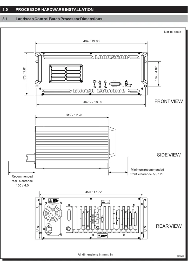
3.0 PROCESSOR HARDWARE INSTALLATION
3.1 Landscan Control Batch Processor Dimensions
298002
Fig. 2 - Landscan Control Batch Processor Dimensions
Not to scale
XXX. XXX. XXX. XX RS 232
TERMI NAL
484 / 19.06
178 / 7.01
467.2 / 18.39
102 / 4.02
312 / 12.28
Recommended rear clearance
100 / 4.0
Minimum recommended front clearance 50 / 2.0
450 / 17.72
SIDE VIEW
REAR VIEW
FRONT VIEW
Page 5 198.298
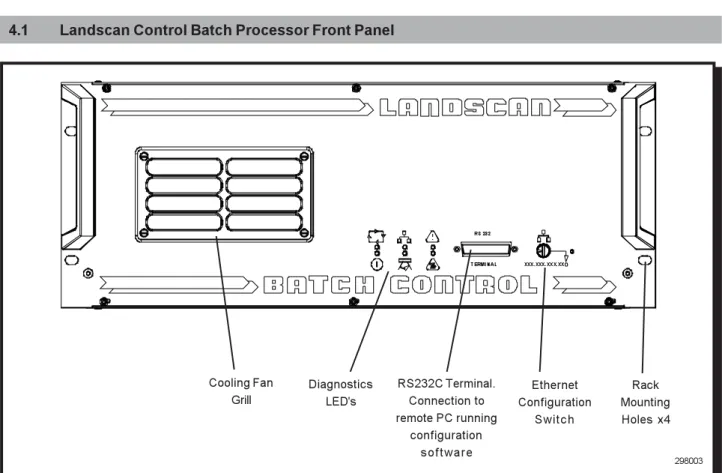
4.1 Landscan Control Batch Processor Front Panel
Fig. 3 - Landscan Control Batch Processor Front Panel
298003 4.0 SYSTEM CABLE CONNECTIONS
The front panel of the Landscan Control Batch Processor is shown in Fig. 3,
illustrating:-•
System Diagnostics LED's•
Ethernet Configuration Switch•
RS232C Terminal Connector for use with a PC or Laptop, running Configuration Software•
Cooling Fan Grill•
Rack Mounting Holes x4Ethernet Configuration
Switch RS232C Terminal.
Connection to remote PC running
configuration s o f t w a r e Diagnostics
LED's Cooling Fan
Grill
Rack Mounting Holes x4
XXX.XXX.XXX.XX RS 232
Page 6 198.298
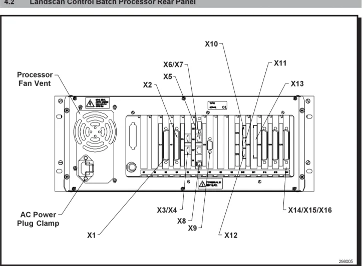
4.2 Landscan Control Batch Processor Rear Panel
Fig. 4 - Landscan Control Batch Processor Rear Panel The rear panel of the Landscan Control Batch Processor is shown in Fig. 4,
illustrating:-• X1 Encoder Input
• X2 Encoder I/O
• X3/X4/X5/X8 Service Interface Connections (Land Use Only)
•
X6/X7 Ethernet Connection• X9 RS232C Connection
• X10 System Alarm
• X11 Remote Laser Control
• X12 Scan Valid Retransmit
• X13 LSP Linescanning Thermometer Connector
• X14/X15/X16 DAIO Cards
298005
X1
X2
X6/X7 X11
X10
X9 X3/X4
X13
X14/X15/X16
X12 Processor
Fan Vent
AC Power
Plug Clamp X8
Page 7 198.298
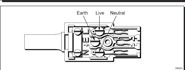
4.3 Mains Power
The processor requires a three-wire a.c.supply, that includes an earth ground connection.
Warning
RISK OF ELECTRIC SHOCK
The a.c. supply and associated wiring must conform to local regulations for voltage and power rating. Failure to provide an earth ground connection can cause electric shock and improper operation of the equipment. Ensure that the earth ground wire has a current carrying capacity equal to, or greater than the largest power conductor.
Ensure that the a.c. supply to this equipment is connected through an accessible isolator switch. The power consumption of the Landscan Control Batch Processor is approximately 60W and the unit must be fused independently with a 5amp fuse.
298004
Fig. 4 - IEC Mains Socket Wiring Diagram
Earth
Live
Neutral
4.4 Encoder Input (X1)
This 37-way 'D' type connector allows the interface of an incremental encoder (Land part no. 031.834) to the processor. The encoder input can be used for process correction in rotary applications and process speed corrections in linear applications.
4.5 Encoder I/O (X2)
This 37-way 'D' type connector allows the interface of up to two external digital input sensors (Land part no. 031.835) to the processor. The input signals from these sensors can be used to define start and stop parameters of a product as it passes the scanner head.
Page 8 198.298
4.6 External Communications - Ethernet (2-off) (X6/X7)
The ethernet connections (2-off) provide a high-speed communications interface. The user is able to request live data and remotely configure the processor parameters from a remote PC.
To make use of the external communications, commands must be sent to the processor using the LAND specified format. Full details of the LAND messaging interface are given in the Processor Configuration Software User Guide. The processor provides a connection for a 10BASE-T RJ45 Shielded Twisted Pair (STP) connector of CAT5 specification.
The general cable recommendation is to use shielded 10BASE-T LSOH Category 5/Level 5 STP cable.This provides protection from electromagnetic interference in industrial environments. The use of unshielded 10BASE-T LSOH Category 5/Level 5 UTP is only recommended for areas that are guaranteed to be free from severe electromagnetic interference.
The maximum cable length allowed is 100m / 328ft, which may be extended by utilising external network repeaters. For single head, single display systems, a 'peer to peer' network crossover cable is recommended.
Fig. 5 - Ethernet Connection
298005
X6/X7
4.7 External Communications - RS232C Connection (X9)
The serial connection provides the means by which a user can request statistical data and remotely configure the processor parameters from a remote PC.
To make use of the external communications, customers must send commands to the processor using the LAND specified format. Full details of the LAND messaging interface are given in the Processor Configuration Software User Guide.
The general recommendation for cable is 3-core with overall screen.
Fig. 6 - Serial RS232C Connection
298006
X9
Pin 3 : Transmit (Tx)Pin 2 : Receive (Rx)Page 9 198.298
4.9 Remote Laser Control Input (X11)
The remote laser control input allows the scanner head laser to be remotely operated. The laser contacts can be operated by utilising an external switch or relay contacts (closed contacts activate the scanner head laser and open contacts make the scanner head laser inactive).
Fig. 8 - Remote Laser Control Contacts
298008
1
2
X11
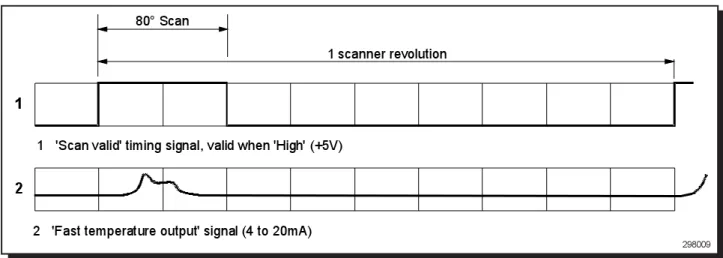
The processor provides a scanning head scan valid output. This signal can be used to synchronise the process to the scanner head data acquisition rate.
4.10 Scan Valid Retransmit (X12)
1
2
80° Scan
1 scanner revolution
1
2
'Scan valid' timing signal, valid when 'High' (+5V)
'Fast temperature output' signal (4 to 20mA)
Fig. 9 - Scan Valid Timing Diagram
298009
4.8 System Alarm (X10)
The processor provides a system alarm relay output that indicates system event warnings eg. scanner head faults. Three contacts are provided; [NO] 'Normally open', [NC] 'Normally Closed' and [C] 'Common'.
The relay rating is 2A @ 30V d.c. maximum.
Fig. 7 - System Alarm Contacts
298007
X10
NO
NC
C
Page 10 198.298
Fig. 10 - Scan Valid Contacts
298010
1
2
sv
X12
Pin 1 : +5V TTL Output Pin 2 : 0V
4.11 LSP/LS Linescanning Thermometer Connection (X13)
The X13 connector allows an LSP or LS series linescanning thermometer to be interfaced to the Landscan Control Batch Processor unit. The selection of either an LSP or LS system is determined by setting jumper links on the X13 PCB.
Fig. 11a - Connection Contacts
298011a S1 S2E1 E2 AT1 AT2 SV1 SV2 FT1 FT2V1 V2 SCR
X13
298011bFig. 11b - LSP and LS System Jumper Link Settings
LSP Scanners - 1&2 Linked (default)
LS Scanners - 2&3 Linked
Up to 3 Digital/Analog Input/Output Cards (DAIO) may be fitted. Each card provides the following inputs and outputs:
Fig. 12 - DAIO Card Inputs and Outputs (single card application)
298012
*The status of each channel is updated once per scan line.
INPUTS OUTPUTS No. OF CHANNELS SPECIFICATION
Digital 4* Closed contact with respect to isolated 24V,
active high
Analog 4* Differential, milliamp or voltage - link selectable.
0 to 1/2/5/10V range, scaling span and offset - independently software selectable
Digital 4* Voltage-free relay outputs
Analog 4* 0 to 20mA / 4 to 20mA,
- independently software selectable
Page 11 198.298
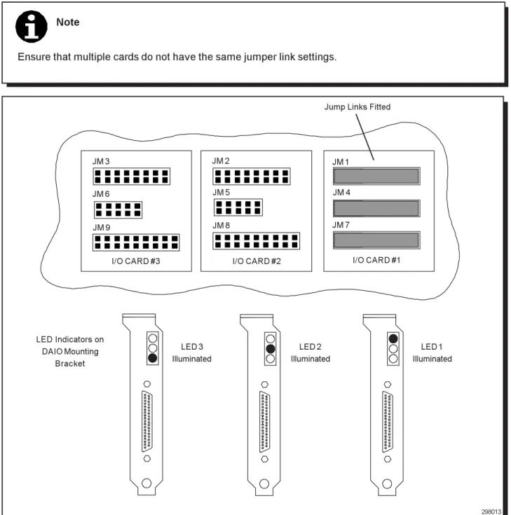
When used with the Landscan Control Batch Processor, each DAIO card fitted must be set to a unique card number. This is done by fitting the 3 jumper links on the headers in the appropriate card number position (see Fig. 13).
4.12.1 Card Programming
Note
Ensure that multiple cards do not have the same jumper link settings.
298013
JM 3 JM 2 JM 1
JM 6 JM 5 JM 4
JM 9 JM 8 JM 7
I/O CARD #3 I/O CARD #2 I/O CARD #1
Jump Links Fitted
Fig. 13 - DAIO Card Programming
LED Indicators on DAIO Mounting
Bracket
LED 3 Illuminated
LED 2 Illuminated
LED 1 Illuminated
Page 12 198.298
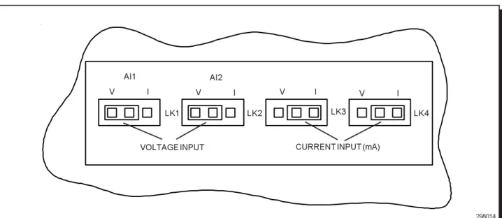
4.12.2 Analog Input Link Positions
The analog inputs can accept either voltage (V) or current (mA) signals. Each of the four channels may be independently set using jumper links.
For voltage input:
Set the appropriate link to "V" (see Fig. 14)
Select the required voltage input range in the Processor Configuration Software (see Processor Configuration Software User Guide)
For current input:
Set the appropriate link to "I" (see Fig. 14)
Select the voltage input range in the software to 0 to 5V.
4.12.3 Multiple DAIO Cards
When three DAIO cards are fitted, they provide a maximum of: 12 channels of Analog Output
12 channels of Digital Output 8 channels of Analog Input 8 channels of Digital Input
298014
Fig. 14 - Analog Input Link Positions
I V
LK4
VOLTAGE INPUT
LK3 LK2
LK1
I V I
V I
V
CURRENT INPUT (mA)
AI1 AI2
Note
When a third DAIO card is fitted, the Analog and Digital inputs of the card are disabled. This is because only 8 inputs are available at any time.
Page 13 198.298
37-WAY 'D' CONNECTOR PIN NO. FUNCTION CHANNEL
1 Digital Input Ch1
2 Digital Input Ch2
3 Digital Input Ch3
4 Digital Input Ch4
5 24V (Isolated)
6 24V (Isolated)
7 0V (Isolated)
8 0V (Isolated)
9 Digital Output Normally Open Ch4
10 Digital Output Normally Closed Ch4
11 Digital Output Common Ch4
12 Analog Output Ch1
13 Return Ch1
14 Analog Output Ch2
15 Return Ch2
16 Analog Output Ch3
17 Return Ch3
18 Analog Output Ch4
19 Return Ch4
20 Relay Output Normally Open Ch1
21 Relay Output Normally Closed Ch1
22 Relay Output Common Ch1
23 Relay Output Normally Open Ch2
24 Relay Output Normally Closed Ch2
25 Relay Output Common Ch2
26 Relay Output Normally Open Ch3
27 Relay Output Normally Closed Ch3
28 Relay Output Common Ch3
29 No Connection
-30 Analog Input + Ch1
31 Analog Input - Ch1
32 Analog Input + Ch2
33 Analog Input - Ch2
34 Analog Input + Ch3
35 Analog Input - Ch3
36 Analog Input + Ch4
37 Analog Input - Ch4
298015
Page 14 198.298
4.13 RS232C Terminal Connector (Front Panel)
The front panel RS232C terminal connector is intended to be used in conjunction with a laptop PC running the Processor Configuration Software.
A serial cable is supplied with the the Landscan Control Batch Processor for this purpose.
If the RS232C cable supplied is not suitable for the dedicated type of portable computer to be used, then an alternative can be supplied (upon request), or a suitable connector can be manufactured and wired as shown below:
Fig. 16 - Wiring Diagram for Processor to PC Connection Cable Consult the portable PC User Guide for pin connections to the serial port (COM1).
GND
Rx
Tx
7
3 2
Portable computer Serial Port (COM )1
Landscan Control Batch Processor front panel 25-way serial communications terminal connection
Page 15 198.298
5.0 SYSTEM DISPLAY
The Landscan Control Batch Processor has six LED's located on the front panel, which are used to indicate system events and system status. The LED's provide immediate diagnosis of the current status of the unit and allow detailed fault finding.
Fig. 17 - Front Panel LED's
298017 TERMINAL RS232 IP ADDRESS XXX.XXX.XXX.XX !
Each of the display LED's has a number of possible states which can be used to diagnose the current status of the system.
5.1 System Display LED's
Symbol Description LED Constant On LED Flashing On LED Off
Power - This indicates that power
has been applied to the unit
System Running - This indicates
that the software is running and acts as a visual watchdog
Scanner - This is an indication of the
status of the scanner
Ethernet Comms - This is an
indication of the status of the Ethernet network adapter and network activity
Temperature Alarm - This indicates
the processor and scanner internal ambient temperature sensor status
System Alarm - This is an indication
of the status of the system alarm
Power OK
Fault
Hardware OK
Stabilising Scan Valid Ethernet Adapter OK Network not active
High Temp trip
Fault
Fault
Running OK Software watchdog
Hardware OK Receiving valid data Ethernet Adapter OK Network activity
Highest Temp trip
System Alarm active
Fault Fault Fault Fault Temp OK System OK
It is possible to diagnose the system to individual hardware and software components using the display and the 'System Fault Diagnosis Chart' found in Appendix A.
Page 16 198.298
6.0 ETHERNET CONFIGURATION
The Ethernet network is configured using the Ethernet ID switch located on the processor front panel.
Fig. 18 - Ethernet ID Switch
298018
9
XXX.XXX.XXX.XX
IP ADDRESS
The rotating switch on the front panel allows the user to set a unique number for each unit. This number is the lowest digit of the IP addresses stored in the unit for each of the two network adapters.
XXX.XXX.XXX.XX_
On power-up, the unit then reads the switch and creates the unit's IP addresses from the base address plus the switch setting.
For example, if the base address of the unit was 10.1.10.100 and the switch setting was 5 the actual IP addresses used by the unit would be 10.1.10.105 and 10.1.10.115.
This allows for all units on the network to be configured with the same base address and have a unique switch setting. Using this system allows units to be moved around the network without the need to use configuration software to change network settings.
The base address of the unit can be changed using the Configuration Software, details of which are explained in the Configuration Software User Guide.
Note
The switch is only read on power-up of the unit and any changes to the switch position, following this, does not change the network IP address. It is therefore necessary when applying power to the unit, to ensure that the IP switch setting is in the relevant position.
Page 17 198.298
7.0 QUICK-START GUIDE
This section describes a sequence of actions which confirm that the system is functioning correctly.
In the event of verification failure, refer to the Processor Configuration Software User Guide. If any further problems are encountered, contact Land Instruments International for assistance.
7.1 Select the Ethernet ID Setting
Before the unit is powered-up, it is necessary to ensure that the Ethernet switch, located on the front panel of the processor, is set to the required value.
Refer to Section 6.0 for details of network configuration and Ethernet ID selection.
7.2 Applying Power to the Processor
When power has been applied to the processor unit, the display 'Power' LED should be illuminated. Refer to Section 5.0 for details of the display start-up sequence.
7.3 Display System Status
After the start-up procedure has ended, the display begins to indicate the current system status. This depends on the connections made to the unit at this point. The 'System Running' LED should be flashing to indicate that the unit is running correctly.
Refer to Section 5.0 for details of display status indication.
7.4 Connection of the Processor to the Personal / Laptop Computer
Connect the supplied RS232C Serial Comms lead to the 25-way terminal on the front panel of the processor and to the 9-way COM 1 serial port of the dedicated portable PC.
COM 1
SERIAL POWER
LSP PROCESSOR FRONT PANEL
RS 232C SERIAL COMMS CABLE (SUPPLIED)
PORTABLE COMPUTER REAR PANEL
9 - WAY CONNECTOR 25 - WAY CONNECTOR
RS232
TERMINAL XXX.XXX.XXX.XX I P A DD RE S S
Fig. 19 - Processor to Portable PC Connection
Page 18 198.298
7.5 Communicating with the Processor
The following section describes how to communicate with the processor for the purposes of system configuration and how to monitor data acquisition of the processor.
Ensure that the Processor Configuration Software has been fully installed.
Start the 'Processor Configuration Software' by selecting the desktop icon or the program menu option. The configuration software starts immediately and attempts to communicate with the processor.
Following successful communications with the processor, the user is prompted to perform an upload of the current processor configuration.
Confirm the upload. The following upload progress dialog box is then displayed.
Fig. 20 - Upload Dialog Box
298020
Following a successful processor configuration upload, the current processor configuration is displayed in the main window of the software.
Page 19 198.298
Fig. 21 - Main Window Dialog Box
298021
The status bar located at the bottom of the main window should indicate that the system is running correctly ('System OK') and the configuration status box should indicate that this is a live configuration ('Live Configuration'). The processor is now operating correctly and communicating with the Processor Configuration Software. The Processor Configuration Software indicates system faults by turning the 'Main Window' status bar to red. A description of the fault will be indicated on the status bar. Further diagnosis is possible from the processor diagnostics window.
Page 20 198.298
7.6 Temperature Data Capture
The following section assumes that a target temperature is available for verification.
After completing the steps detailed in the previous section, select the 'Configuration' dialog box and select the specific system parameters including 'Scanner Type' and 'Units of Measurement'.
Select the 'Processor Download' option from the toolbar and confirm the action. A 'Download Progress' dialog box will be displayed, indicating the successful download of the new configuration.
Fig. 22 - Download Dialog Box
298022
Select the 'Profile Display' option from the Processor Configuration Software toolbar. The 'Scanner Profile Display' window will be displayed, indicating the 'Target Temperature Profile'.
Fig. 23 - Temperature Profile Display
298023
Confirm that the data displayed is as expected for the current temperature and that the temperature range shown on the display matches the system scanner type.
Page 21 198.298
8.0 ROTARY MACHINE APPLICATIONS
8.1 Overview
On systems where a scanner head is utilised on a rotary machine, it is necessary to correct the image as it appears in the scanner field of view, because of distortion caused by the rotational effect.
To calculate this correction, the LSB requires a positional input and a machine reference point, that allow the processor to determine the current position of the product relative to the scanner datum. The positional input is provided by a rotary encoder and the machine reference point by a digital input sensor.
8.2 Installation of Hardware
8.2.1 Scanner
To allow the rotary geometry correction to be applied to the product data, the scanner head must be positioned in the correct orientation. The following criteria must be met;
•
The scan line is aligned with the centre of the machine.•
The scanner height must ensure a given scan width slightly greater than the maximum product size.8.2.2 Encoder
To ensure maximum efficiency of the machine encoder, the following criteria must be met;
•
The encoder should ideally be positioned as far away from the centre of the machine as possible. This ensures that the greatest measurement circumference and the highest possible position resolution are achieved.•
The encoder measurement wheel must remain in contact with the machine for the full machine revolution.•
The encoder mounting bracket should be fitted with the contact spring compressed to approximately 50% of its full compression (approx. 25mm). This ensures that the spring maintains tension between the machine surface and the measurement wheel during movement in both directions.8.2.3 Digital Input sensor
To ensure maximum efficiency of the digital input sensor, the following criteria must be met;
•
The magnetic digital input sensor should be mounted onto the machine such that it provides a trigger signal to the processor, just prior to one of the product stations passing through the scanner field of view.•
The magnet should be positioned on the rotating section of the machine, with the sensor mounted to a fixed point between 10mm and 20mm from the magnet. The sensor incorporates an indicator lamp which illuminates when the sensor and the magnet are positioned and activated correctly.8.3 Software
The setup and configuration of the hardware used in a rotary machine application is carried out utilising the Landscan Configuration software. The use of this software is described in detail in the Landscan Configuration Software User Guide and the accompanying on-line help facility.
Page 22 198.298
9.0 ACCESSORIES
The following accessories are available from Land Instruments International:
DAIO Board Upgrade .. 031.788
Up to 3 DAIO boards may be fitted to the Landscan Control Processor. If the following accessories are to be utilised, then each DAIO card used requires a cable and termination block.
DAIO Connection Cable 1m/3.3ft .. 203.879
This 1m cable is supplied with the relevant connectors pre-wired, to interface a DAIO card to a DIN rail mounted DAIO I/O Termination Block.
DAIO Connection Cable 2m/6.6ft .. 203.880
As 1m cable.
DAIO Connection Cable 4m/13.2ft .. 203.881
As 1m cable.
DAIO Connection Cable 6m/19.8ft .. 203.882
As 1m cable.
Air Intake Filter .. 031.784
This replacement filter is used in the processor fan air intake assembly. (See section 10.0 MAINTENANCE for details on filter replacement)
37-Pin, D-Connector For DAIO Card .. Connector 206.599
.. Backshell 206.600
Replacement 37-pin, D-type connector and backshell assembly.
Plug, X13 Board Connector .. Plug 212.388
.. Cover 212.391
Replacement plug and cover for the X13 board connector.
DAIO I/O Termination Block (DIN Rail Mounting) .. 212.414
This DIN rail mounted termination block allows easy connection of I/O from the Landscan Control Batch Processor to the system control panel.
Digital Sensor Assembly .. 031.835
The digital sensor assembly can be used in conjunction with the position pack, to provide product trigger signals for the LSB.
212.414
Encoder Sensor Assembly .. 031.834
The encoder sensor assembly provides a position or speed input to the LSB processor, when used in conjunction with the position pack.
Position Pack .. 031.850
The position pack provides connection terminals and supply voltage for the optional encoder sensor and digital sensor assemblies.
Page 23 198.298
10.0 MAINTENANCE
The Landscan Control Batch Processor requires no scheduled maintenance, but it is recommended that the unit is kept clean and free from any contaminants.
The processor cabinet utilises two internal fan assemblies to continuously circulate air around the components of the processor. The air intake for these fans has a cover assembly containing a filter that requires changing when found to be contaminated. The following procedure details how to replace the cabinet filter:
•
Ensure that the power to the processor is turned off.•
Remove the M3 countersunk slot-head screws (x4) from the air intake cover.•
Remove the filter cover assembly (cover, filter and filter grill) from the processor cabinet air intake.•
The removed items should easily dismantle, allowing the contaminated filter to be replaced.•
Place the new filter into the recess in the filter cover and position the filter grill on top of the filter.•
When the filter cover assembly is correctly positioned over the air intake, secure using the M3 screws.•
Apply power to the unit and ensure that the cabinet fans are functioning correctly.Note
It is important that the cabinet filter is changed when required. Failure to do so may result in component overheating and subsequent damage.
Page 24 198.298
Appendix A SYSTEM FAULT DIAGNOSIS CHART
Faulty Processor Card Faulty Processor Card OFF OFF Flashing Unit In Run Mode Power LED Run LED Faulty Power Supply ON LED Flashing ? System Alarm LED Flashing ? Scanner LED LED Flashing ? Temp LED Ethernet LED LED Flashing ? Faulty Processor Card No Scan Valid Signal Faulty Processor Card Comms Driver Problem Faulty Processor Card Ambient Temperature OK Faulty Processor Card System OK Faulty Processor Card No Valid Data Available Faulty Processor Card Comms OK Not Active Faulty Processor Card Temperature >55°C Faulty Processor Card Fault Faulty Processor Card Receiving Valid Data Faulty Processor Card Comms OK Active Faulty Processor Card Temperature >60°C Faulty Processor Card System Alarm Active
NO NO NO NO
OFF OFF OFF OFF ON ON ON ON
YES YES YES YES
Warning