Simulation of an Inverter-Based Dg System by Using Voltage Control of DC
Link for Islanding Detection
V PRAVEEN KUMAR
P.G. scholar, Dept of EEE
Trr Engineering College,
Hyderabad, Telangana, India
Abstract
-
This paper presents a novel strategy for islanding detection of distributed generation (DG). During islanding condition the main idea of this paper is to change the dc-link voltage considering the PCC voltage changes. A simple islanding detection scheme has been designed based on this idea. The proposed method has been studied under multiple-DG operation modes and the UL 1741 islanding tests. The simulations results are carried out in MATLAB/SIMULINK environment. The proposed method is capable of detecting islanding accurately within the minimum standard time and it has a small non detection zone as simulated in the paper.INTRODUCTION
With the increasing distributed generation penetration in to the power system the protection and islanding detection of DGs is necessary for its stable and reliable operation.[1]. Islanding protection is one of the most important issues to address in DG applications. In [2] and [3], the islanding is defined as a condition in which a portion of an electric power system is solely energized and separated from the rest of the electric power system. The DG unit should detect the islanding and disconnect the islanded system in a timely manner to avoid damages [2]. Unintentional islanding of DG may result in power-quality (PQ) issues, interference with protection devices, and reliability reduction for customers. There are three main methods of islanding detection: 1) passive, 2) active, and 3) communication-based methods [4].
Passive methods continuously monitor the system parameters, such as voltage, frequency, harmonic distortion, etc. In this technique, one or more of these parameters has/have been considerably changed when the grid is islanded. Setting a proper threshold can help to differentiate between the islanding and grid-connected conditions. The over/under frequency protection method uses upper and lower frequency thresholds, which are usually set at 60.5 and 59.3 Hz, respectively [3]–[5]. The
over/under voltage protection method uses upper and lower voltage thresholds, which are set at 110% and 88% of the nominal voltage value , respectively [3]–
[5]. Upper and lower thresholds have been used to avoid unwanted tripping of the DG due to other system disturbances [4]. Sometimes the load closely matches the DG capacity. In this case, the amount of frequency or voltage deviation will not be sufficient to trigger the islanding detection system [4]. Several passive islanding detection methods are available, such as under voltage/overvoltage [6], [7]; under frequency/over frequency [6], [7]; rate of change of active power [8], [9]; rate of change of frequency (ROCOF) [7], [10]; and [11] rate of change of frequency over power [12], voltage and power factor changes [13], phase jump detection [14], and voltage unbalance and total harmonic distortion [15], [16]. Passive islanding detection methods suffer from large non detection zones (NDZs) [3], [4]. NDZs are defined as a loading condition for which an islanding detection method would fail to operate in a timely manner.
Active techniques have been designed to force DG to be unstable in islanding mode [17] and interact with the operation of the power system directly [18]. The main advantage of active techniques over passive techniques is their small NDZ [7]–[19] and [20]. Active methods include slide-mode frequency shift [21], active frequency drift or frequency bias [22], Sandia frequency shift [23], and harmonic distortion base [19]. Active methods have a smaller NDZ and can degrade the PQ of the power system [24], [25]. Communication-based methods do not have any NDZ, but they are more expensive than the former methods [24].
controllable dc voltage source. The main idea of this paper is to change the dc-link voltage considering the PCC voltage changes during the islanding condition. A simple and easy-to-implement method, such as the over/under voltage protection (OVP/UVP), can be used to detect an islanding condition. Once the magnitude of voltage exceeds a determined threshold value, an islanding condition is detected and DG is disconnected.
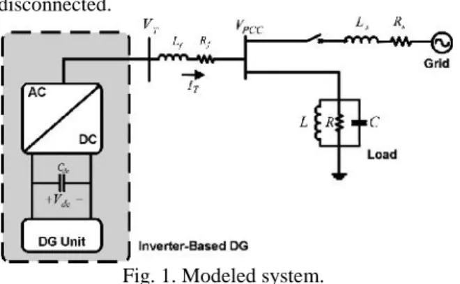
Fig. 1. Modeled system.
II. SYSTEM UNDER STUDY
The system, which has been studied in this paper, is shown in Fig. 1. This system consists of a distribution network modelled by a three-phase voltage source behind impedance, a load modelled by a three-phase constant impedance, and a DG system. The DG is modeled by a controllable dc voltage source behind a three-phase inverter. The rating of this inverter is 100 kW. The other parameters have been given in [4], [5], and [17].
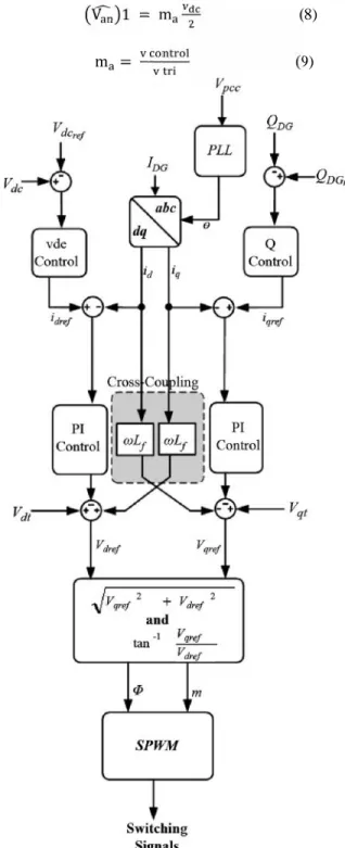
Fig. 2 shows the control scheme based on dq synchronous reference frame. In this system, the dc-link voltage controller and reactive-power controller determine d and q components, respectively. The input power extracted from the DG unit is fed into the dc link. Therefore, the voltage controller counteracts the voltage variation by specifying an adequate value of the axis inverter current to balance the power flow of the dc link [26].
The reactive power controller, shown in Fig. 2, specifies the reference value for the q component of the converter current. The reactive power reference value is set to zero in order to model a unity power factor DG operation. Also, Fig. 2 shows two proportional-integral (PI) controllers for the - and –
axis current controls. The outputs of these controllers obtain the reference voltages for the PWM signal generator. The main features of the current control strategy are the limitation of the converter output current during a fault condition, providing over current protection, and reducing the fault current contribution of the unit [26].
The instantaneous real and reactive power could be written in terms of the dq axis components, as follows [27], [28]:
=
(1)
=
(2)
Where is the phase peak value of the PCC voltage. and are orthogonal components of inverter currents. The dq components of the voltage and current are constant values in the steady-state condition. Therefore, the controller provides the independent regulation of d and q components [27], [28]. The instantaneous voltages of the three phases could be expressed by the following equation [27], [28]:
i (abc) = − i (abc) + v (abc) − v (abc)
(3)
where i( )represents the DG current three-phase components.R and Lare the filter resistance and inductance, respectively.v( ) and v ( ) represent the DG terminal and PCC three phase
voltages, respectively. By using Park’s
transformation [27], (3) can be transformed to the rotating synchronous reference frame, as follows [4], [27] and [28].
i
i =
ω −ω
i
i + VV −V−V
Or (4) i i = 0 0 i
i + uu (5)
u = V − V + ωL i (6)
u = V − V + ωL i (7)
The DG interface control is modified by using the set of equations shown in Fig. 2. The magnitude and angle of the modulating signal are calculated and then the switching pattern of the inverter has been determined.
constant input dc voltage [29]. In the linear region (i.e. m ≤ 1.0), the fundamental frequency component in the output voltage (V ) determines the amplitude modulation ratio (m ), by the following equation [29]:
V 1 = m (8)
m = (9)
Fig. 2. Block diagram of the DG inverter controller.
wherev control is the peak amplitude of the control signal andv tri the is the amplitude of the triangular signal. Therefore, the line-to-line rms voltage at the fundamental frequency can be written, as follows [29]:
V ( ; ) =√√ V 1 = √√ m v
≈ 0.612m v (m ≤ 1.0) (10)
Now, the following equations can be written for v and :v
v = 0.612. m v cos(∅) (11)
v = 0.612. m v sin(∅) (12)
where ∅is the angle by which the inverter voltage vector leads the line voltage vector. In a lossless inverter, the instantaneous power at the ac and dc terminals of the inverter is equal. This power balance can be written, as follows:
v . i = v i + v i (13)
At the dc link, we have
i = c . v (14)
By using (4) and (11)–(14), the following state equations can be written [27]:
i i
v =[A] i i
v +
0 0
0 0
v
v ∆
[A] =
⎣ ⎢ ⎢ ⎢
⎡ ω . cos ∅
−ω . sin ∅
∗ . cos ∅ ∗ . sin ∅ 0
⎦ ⎥ ⎥ ⎥ ⎤
(15)
III. PROPOSED ISLANDING DETECTION METHOD
A. Linearization of System State Equations
To measure the impact of deviation of
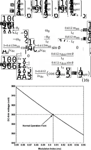
m on dc-link voltage,∅ has been kept constant and only m has been considered as a variable. As a result, (15) is a nonlinear equation. However, for a small perturbation around the equilibrium pointm , the following linear set of equations can be obtained, where subscript 0 denotes steady-state values [27], as shown in (16) at the bottom of the page.
The inverter steady-state model can be obtained from the dynamic model by setting the derivative terms equal to zero. After transformation from to reference frame, the voltages and the currents become dc quantities. Therefore, substituting
d dt
∆i ∆i
∆v = [∆A] ∆i ∆i
∆v + [∆B] ∆V ∆V ∆m [∆A] = ⎣ ⎢ ⎢ ⎢
⎡ ω . cos ∅
−ω . sin ∅
∗ .
cos ∅ ∗ . sin ∅ 0 ⎦⎥
⎥ ⎥ ⎤ [∆B] = ⎣ ⎢ ⎢ ⎢
⎡ 0 . . . ∅
0 . . . ∅
0 0 ∗ . cos ∅. i + sin ∅. i ⎦⎥ ⎥ ⎥ ⎤
(16)
Fig. 3. Steady-state variations of v versusm
v = v ,v = 0,i = I andi = I and Simplification of the steady-state model resulted in the following equation:
−R ωL 0.612m cos ∅
−ωL −R 0.612m sin ∅
0.612m cos ∅ 0.612m sin ∅ 0
I I I = V 0 0 (17)
By solving 17 fori ,i andv we have
I = ( ∅) . V (18)
I = ( ∅). V (19)
V = ( . . . ∅) ( . . . ∅).V
(20) Considering (18) and (19), it is obvious that i and
i do not depend on the modulation index(m ). For the given system, the variations of v versusm can be determined by using (20). By considering it as a constant value, (20) becomes a hyperbolic
equation. But the partm < 0 is not acceptable and just the part 0< m < 1 is the dominant. By scalingm between 0.8 and 1, it can be seen that the deviation of m versus v is linear and usually the normal operating point of the inverter is in this range. The v − m curve of this range has been shown in Fig. 3 Considering (10), we have
V = . . (21)
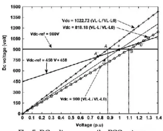
Fig. 4. DC voltage versus PCC voltage characteristic (DG andV are set to 900 V).
In steady-state condition, (10) can be written as follows:
V = . . (22)
V = V . . (23) Considering (20) and Fig. 3, it is obvious that the deviation of m around the operating point does not have any major impact on drifting of the dc-link voltage. Therefore, the modulation index can be assumed to be constant (i.e,m = m ). Then, (23) can be written as follows:
V = V . . (24)
B. − Characteristic
The v − v (v ) characteristic of DG and dc reference voltage have been shown in Fig. 4. In this figure, there are 2 lines which presenting the lower and upper dc voltage limits. Using (24) and assumingv equal to 1 p.u, the slope of these lines
(v )can be determined forv = 900 V and the dc voltage limits. The intersect point of DG and dc-link reference voltage curves is called the islanding operating point. Inthis figure, points “ A” and “ B” represent the operating point of the lower and upper dc-link voltage limits, respectively. Each operating point between these two lines is in the NDZ. In addition, in any kind of loading condition, the dc-link voltage would be placed within or without these boundaries. If v is accommodated within these limits, the voltage deviation will be in the allowable values, and the islanding can occur and will not be detected (NDZ).
In this paper, the DG reference dc voltage curve has been modified and expressed by the PCC voltage-dependent line. This line should cross the point which has the rated dc voltage at the rated PCC voltage. It can be expressed by the following equation:
V = K .V + K (25)
Fig. 5. DC voltage versus the PCC voltage characteristic for DG and modifiedV
Fig. 5 presents the dc voltage versus the PCC voltage lines for three (dc voltage) conditions. By changing
“A” and “ B” points to “ ” and “ ” the NDZ is
smaller, because these new points are outside the allowable voltage limits (88% and 110% of nominal voltage), so this condition can be easily detected. As an example, the DG reference dc voltage can be rewritten, as follows:
V = 450.V + 450 (26)
The load condition, which intersects the DG voltage
line at point “ Q” has an active power of100 kW and the voltage of 1 . Equation (26) intersects the
lower and upper limits at points “ A” and “B ,”
respectively. These two points correspond to voltage levels that are beyond the allowable voltage levels. Thus, these loading conditions can be easily detected by using the over/under voltage protection (OVP/UVP) methods. As a result, a reduction in the NDZ can be achieved. The reference dc voltage can be expressed by a negative slope, as follows:
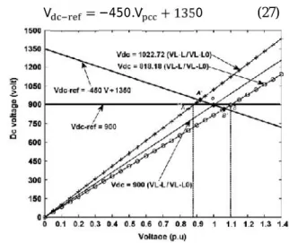
V = −450.V + 1350 (27)
Fig 6 DC voltage versus the PCC voltage characteristic, effect of negative slope.
Fig. 6 presents the dc voltage versus PCC voltage lines for the same conditions, presented in Fig. 5. The lower and upper limits intersect the new DG line by
(27) at points “ ” and “ ,” respectively. The voltage levels of these two points are in the NDZ. Therefore, these loading conditions will not be detected
by using OVP/UVP methods. Therefore, the negative slope in (27) will lead to an increase in the NDZ and the positive slope can reduce the NDZ. The values of parameters k and k have been chosen so that the DG v − v slope is placed higher than the slope of all possible load lines within the NDZ. Considering 24), the following equations have been used to tunek andk
= |V = V | (28)
= (29)
V = V (30)
Fig. 7. DC voltage versus the PCC voltage characteristic, with an effect of the selection of (31).
Based on these equations, it can be stated that
k =vv (v = 900volts, v = 1 p. u. )
And k =0are a suitable condition. But it must be mentioned that k cannot be equal to zero. This is because ifk = 900 andk 0, then the system will be very sensitive to PCC voltage perturbations and it will lead to undesirable system tripping. To protect the system from this situation, based on the simulation results and IEEE 1547 Standard and other power system standards (the allowable voltage deviation for DGs below 500 kVA is 10% of the nominal voltage), it is supposed to have a good selection for ,k when it is about 10% of the dc link voltage. As a result, (25) has been changed into the following form:
V = 810.V + 90 (31)
Fig. 8. NDZ of theV − V characteristic for a different amount ofK andK
C. Performance Evaluation
The performance of the proposed islanding detection method as well as its NDZ depends on the
variation (Δv) will result in a dc-link voltage variation which could be expressed, as follows:
V = V . = K . V + K (32)
(V + ∆V ) ( ∆ ) =K × V (1 +
∆V+K2 (33)
(V + ∆v ) = K ∗ V (1 + ∆V)(1 + ∆V) + K
(34)
Table I shows the calculated NDZs for different values ofk andk presented in this paper. It can be seen that the selection of thev − v characteristic will have a great impact on NDZ. If the boundary between lower and upper limits of NDZ is a large number, it will lead to a wide NDZ. In some cases, NDZ has a large gap (e.g., case No. 2),
This paper examines the NDZ of an OVP/UVP and OFP/UVP islanding scheme in case of using the implemented v − v characteristic for different amounts ofk andk . The results have been plotted in Fig. 8. small (e.g., case No. 3). NDZ can either be represented in terms of power mismatch or in terms of the load and accurate presentation of the NDZ can be found in [17]. This paper examines the NDZ of an OVP/UVP and OFP/UVP islanding scheme in case of using the implemented V −
V characteristic for different amounts of and . The results have been plotted in Fig. 8
IV. SIMULATIONRESULTS
In this section, the test system shown in Fig. 1 has been simulated by MATLAB/SIMULINK. The system, DG, and load parameters are listed in Table II. The parameter has been set to 0 MVAR. The Islanding detection method has been tested for load with a quality factor of 1.77. The proposed islanding detection method has been also tested for various loading conditions specified in the UL 1741 Standard [3].
A. UL 1741 Testing
Based on the UL 1741 Standard, the active load power is adjusted to set the inverter at 25%, 50%, 100%, and 125% of the rated output power of the inverter. The reactive power has been adjusted between 95% and 105% of the balanced condition (unity power factor loading) in 1% steps [3]. The islanding detection scheme is tested based on the procedure presented in [3]. But all results have not been presented in this section. The DG interface has been equipped with theV characteristic given in (31) and islanding has occurred at t=0.8 s. The first simulation result using the proposed method is shown in Fig. 9. This figure shows the voltage at the PCC during an islanding condition, for the active load power adjusted at 50%, of its rated output power. The reactive power has been adjusted at 100% of the balanced condition. As can be seen in
Fig. 9. PCC voltage using the proposedV − V characteristic for different loads.
Fig. 9, the PCC voltage exceeds the OVP/UVP thresholds in less than 100 ms (after the occurrence of islanding). Fig. 10 shows the voltage at the PCC during an islanding condition, for the following cases
Fig 10(a) Case( 1) The load has been adjusted to operate at 100% of rated active power with 101%
Fig 10(b) Case (2) The load has been adjusted at 100% of the rated active power with 100% reactive
power.
Case 3) The load has been adjusted at 100% of its rated active power with 99% reactive power.
It can be seen in Fig. 10 that the operation of the DG unit is stable as long as it is connected to the grid. After islanding instant t = 0.8 s), the DG loses its stable operation, and the PCC voltage exceeds the OVP/UVP threshold values in less than 110 ms
B. Effect of Load Switching
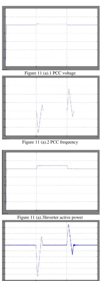
The proposed islanding detection method has been tested for load switching in the grid-connected operation mode. In parallel with the old load, which has been presented in Fig. 1, the new load has been switched at t= 0.5 s and disconnected at t =1 s. Three cases have been simulated in this test. In all cases, the load apparent power is equal to 100 but the power factor is 0.8 lead, 1.0 and 0.8 lag. The simulation results that include the PCC voltage and frequency, and the DG active and reactive power outputs for three different loading conditions have been presented in Fig. 11 (a) shows the 100kva load with o.8 lead power factor
Figure 11 (a).1 PCC voltage
Figure 11 (a).2 PCC frequency
Figure 11 (a).3Inverter active power
Figure 11(b) shows the 100 KVA load with a unity power factor
Figure 11 (b).1 PCC voltage
Figure 11 (b).2 PCC frequency
Figure 11 (b).3 Inverter active power
Figure 11 (b).4 Inverter reactive power Figure 3 shows 100kva load with 0.8 lagging power
factor
Figure 11 (c).1 PCC voltage
Figure 11 (c).2 PCC frequency
Figure 11 (c).3 Inverter active power
The voltage and frequency variations can be seen when the load is switched on and off. For simulated cases, the voltage and frequency variations are within the standard values. It is obvious that the proposed method does not interfere with the power system operation during normal conditions figure
C. Effect of Load Quality Factor
The IEEE Standard 929 proposes the use of
Q ≤ 2.5 for tests. Yet, recent standards (IEEE 1547.1) propose testing islanding with loads having a quality factor of 1 [30]. The UL 1741 test specifies that an islanding detection method must succeed in detecting the islanding phenomenon within 2 s for RLC loads withQ ≤1.8 [4]. For the system shown in Fig. 1,Q has changed in the range of 0.5 to 4.2 by adjusting the load inductance and capacitance
Fig 12(a) PCC voltage for =0.5
Fig 12(b) PCC voltage for =1
Fig 12(c) PCC voltage for =1.77
Fig 12(d) PCC voltage for =2.12
Fig 12(e) PCC voltage of =3
Fig 12(f) PCC voltage for =4.2
Fig. 12 (a-f) shows the PCC voltage for different values of As can be seen in this figure, the voltage has exceeded the OVP/UVP thresholds in less than
VI. CONCLUSION
This paper proposes a novel method for islanding detection of an inverter-based DG unit in this dc link voltage is being changed by comparison with the PCC. The characteristic has been chosen so that the DG maintains its stable operation in grid-connected and islanding condition modes. Applying the proposed characteristic to the DG results in a simple islanding detection method. which can be similar to OVP/UVP protections. The method is being simulated for the inverter-based DG unit under the DG operation mode and the UL 1741 test conditions. The simulation results show the effectiveness of the new islanding detection method for different operating conditions as simulated in the paper. In addition, it has been shown that this method does not distort any voltage or current waveforms by injecting perturbations and, thus, it has high performance from a PQ point of view. This method accurately detects the islanding condition with in a minimum standard time with the smaller NDZ.
REFERENCES
[1] C. Ma, Z. Lu, W. H. Tang, Q. H.Wu, and J. Fitch,
“An agent brokeringbased scheme for anti-islanding
protection of distributed generation,”in Proc. Power Energy Soc. Gen. Meeting, Calgary, AB, Canada, 2009, pp. 1–8.
[2] IEEE Standard for Interconnecting Distributed Resources With Electric Power Systems, IEEE Std. 1547-2003, Jul. 2003.
[3] Static Inverter and Charge Controllers for Use in Photovoltaic Systems Standard UL. Northbrook, IL: Underwriters Laboratories, Inc., 2001.
[4] H. H. Zeineldin, “A droop curve for facilitating Islanding detection of inverter-based distributed
generation,” IEEE Trans. Power Electron., vol. 24, no. 3, pp. 665–673, Mar. 2009.
[5] H. H. Zeineldin and J. L. Kirtley, “A simple
technique for Islanding detection with negligible nondetectionzone,” IEEE Trans Power Del.,
vol. 24, no. 2, pp. 779–786, Apr. 2009.
[6] K. Tunlasakun, K. Kirtikara, S. Thepa, and V.
Monyakul, “CPLD basedIslanding detection for mini
grid connected inverter in renewable energy,” in Proc. IEEE TENCON Conf., Nov. 2004, vol. 4, pp. 175–178.
[7] W. Freitas, W. Xu, C. M. Affonso, and Z. Huang,
“Comparative analysis between ROCOF and vector surge relays for distributed generation applications,”
IEEE Trans. Power Del., vol. 20, no. 2, pt. 2, pp.
1315–1324, Apr. 2005.
[8] F. De mango, M. Liserre, and A. D. Aquila,
“Overview of Anti Islanding Algorithms for PV
Systems. Part II: Active Methods,” in
Proc. IEEE Power Electronics and Motion Control Conf., Jan. 2007, pp. 1884–1889.
[9] M. A. Redfern, O. Usta, and G. Fielding,
“Protection against loss of utility grid supply for a
dispersed storage and generation unit,” IEEE
Trans. Power Del., vol. 8, no. 3, pp. 948–954, Jul. 1993.
[10] J. C. M. Vieira, W. Freitas, W. Xu, and A.
Morelato, “Efficient coordination of ROCOF and frequency relays for distributed generation protection
by using the application region,” IEEE Trans. Power
Del., vol. 21, no. 4, pp. 1878–1884, Oct. 2006. [11] J. P. Moore, J. H. Allmeling, and A. T. Jhns,
“Frequency relaying based on instantaneous frequency measurement (Power Systems),”
IEEE Trans. Power Del., vol. 11, no. 4, pp. 1737–
1742, Oct. 1996.
V.PRAVEEN KUMAR currently pursuing his