105
The Effect of Code Generation Parameters on VEX VLIW Processor
Motahhareh Moravvej HamedaniUniversity of Tehran, Electrical and Computer Engineering Master Graduated,
Received: 14, June , 2018 Accepted: 18, July, 2018 Online Published: 24, September, 2018
Abstract
Embedded systems have a significant character in the present day computing which their domain of applications has extended into many filed like manufacturing, remedy and home automation. In this paper we wants to search about influences of one of such processors in recent technologies. For doing this, in the first section of this paper, we provide reader with general information about Nios processors, and we review some of the main characteristics of this chipset family in comparison with others. In the second section, we review about different flags which are existed in these processors, and how to use such flags. Section 3, will present some real tests on such processors and test the optimality of these processors.
Keywords: Chipset design, VLIW Processor, Code generation parameter.
1. INTRODUCTION
ios II processor is a general-purpose processor with Reduced Instruction Set Computer (RISC) architecture and in the original implementation from Altera, it is
implemented as a 5-stage pipelined design [1].
It has lots of features which can be configured by the user to meet the demands of a desired system. The processor can be implemented in three different configurations [1,2]:
Nios II/f is a "fast" version designed for superior performance.
Nios II/s is a "standard" version that requires fewer resources in an FPGA device as a trade-off for reduced performance.
Nios II/e is an "economy" version which requires the
least amount of FPGA resources, but also has the most limited set of user-configurable features. Its arithmetic and logic operations are performed on operands in the general purpose registers. Nios processor features a large windowed general purpose register file. The size of the register file can be selected among the three predefined values (128, 256, 512), but only a window of 32 registers is visible to programs at
any given time [3].
The data is moved between the memory and these registers by means of Load and Store instructions. The word length of the Nios II processor is 32 bits. All registers are 32 bits long. Byte addresses in a 32-bit
word are assigned in little-endian style, in which the
lower byte addresses are used for the less significant bytes of the word. The Nios II architecture uses separate instruction and data buses, which is often
referred to as the Harvard architecture
The Nios II processor can be used with a variety of other components to form a complete system. These components include a number of standard peripherals, but it is also possible to define custom peripherals. Altera’s DE2 Development and Education board contains several components that can be integrated into a Nios II system. So Nios II processor system is equivalent to a microcontroller or “computer on a chip”
that includes a processor and a combination of
peripherals and memory on a single chip. Figure [1]
shows an example of such a system [4].
Fig1. A Nios II system implemented on the DE2 board
Nios instruction set is optimized for embedded applications. Since the available memory in the embedded systems is limited, all instructions are 16 bits wide, which typically results in reduced code size compared to the architectures with 32-bit instruction word. Nios uses the two-operand instruction format, and several addressing modes. Since 16-bit instruction word severely limits the size of the immediate operands, special 11-bit register (K register) is used to form larger operands. It is preloaded with an immediate value using PFX instruction, and the value in the register can be used by the instruction following
the PFX [4].
Embedded systems play an important role in today computing which their domain of applications has extended into many filed like industry, medicine and home automation. They pose important cost factors like energy dissipation, area and required performance. N
106 Usually they are designed to perform a predefined
function or behavior[2].
Hence profiling is a reasonable method to evaluate the design for a certain application.
To increase instruction level parallelism, VLIW architecture has been proposed in the literature as an alternative to dynamically scheduled superscalar machines in which the compiler statically manages the parallelism. Today, VLIW architectures are employed in high performance servers and digital signal processing (DSP) market. DSPs usually contain hot and small loops called kernels which are good candidates for instruction level parallelism.
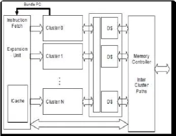
VEX framework is a modular VLIW platform with re-targetable compiler and simulator allowing much
flexibility to wide range of configuration. Figure [1]
shows the VEX architecture which has multiple clusters[1].
Fig2. VEX processor architecture with multiple clusters
2. CODE GENERATION FLAGS
Techniques involving code generation can significantly improve system performance. Some techniques can improve for this purpose, having good information about application and hardware platform techniques can significantly improve performance metric of an applications[2].
VEX compiler efforts plenty of code generation techniques which help the system designer to better meet the design constraints. In this part we explored some of these flags and observed their impact on our design constraints, execution time and code size. The
next section describes the used flags in details [1].
3. VEX STATIC AND DYNAMIC PROFLING
VEX compiler determines the available average ILP per function based on the available resources upon compilation. These values are generated by averaging the ILPs of different traces of the scheduled functions and can be calculated for each function in generated
assembly files by pcntl utility [5].
Also by appropriate flags like “-mas_G” application can be instrumented to measure its dynamic ILP at run
time. Static ILP estimation is bound to a basic block which can be a loop or a function. Dynamic ILP on the other hand is calculated for the whole application. Hence static and dynamic ILPs are not easily comparable and they can vary dramatically. This is mostly due to different data flow and control flow of application. It is important to know that stalls also limit the ILP. Table [1] shows the calculation of static ILP for crc32 buf() function by averaging the IPC for different traces during compilation. Tables [2, 3, 4, 5,
6, and 7] show the static and dynamic ILP for different
benchmarsk: CRC, dijkstra, Rijndael and MPEG2 from
Mediabench and Mibench suites [6].
Trace Cycles Opers NOPs IPC
3 2 3 0 1.5
1 45 57 12 1.27
9 2 3 0 1.5
8 2 3 0 1.5
7 2 3 0 1.5
6 2 3 0 1.5
5 2 3 0 1.5
4 2 2 0 1.5
Total= 59 77 12 1.365
Table 1. crc32buf static ILP calculation
Routine Static ILP Dynamic ILP
Main 1.166 -
Crc32file 1.073 -
Crc32buf 1.365 -
Updatecrc32 1 -
Total with stalls - 0.88
Total without stalls - 1
TABLE 2. PROFILING OF CRC32 BENCHMARK
Routine Static ILP Dynamic ILP
Main 1.161 -
Dijkstra 1.337 -
Enqueue 1.365 -
Dequeue 1 -
Qcount 0.66 -
Print_path 0.66 -
Total with stalls - 1.12
Total without stalls - 1.3
Table 3. profiling information of Dijkstra benchmark
Routine Static ILP Dynamic ILP
Set_key 1.5 -
Encrypt 2.55 -
decrypt 2.48 -
Total with stalls - 2.21
Total without
stalls - 2.07
Table 4. profiling information of rijndael encode benchmark
Routine Static ILP Dynamic ILP
107
Encrypt 2.55 -
decrypt 2.48 -
Total with stalls - 2.08
Total without
stalls - 1.96
Table 5. profiling information of rijndael decode benchmark
Routine Static ILP Dynamic ILP
idct 1.26 -
idctcol 1.28 -
idctrow 1.93 -
Quant_intra 1.44 -
Quant_non_intra 1.39 -
Total with stalls - 1.19
Total without stalls - 0.96
Table 6. profiling information of MPEG2 encode benchmark
Routine Static ILP Dynamic ILP
idct 1.26 -
idctcol 1.28 -
idctrow 1.93 -
Quant_intra 1.44 -
Quant_non_intra 1.39 -
Total with stalls - 1.78
Total without stalls - 1.55
Table7. profiling information of MPEG2 decode benchmark
4.RESULT
We test each of ten structures above and recording the information about execution of the program including total cycles, execution cycle, stall cycles and the number of NOP instructions and the size of loaded code. With these data we want to examine the effect of
loop unrolling pragma on the execution time. Table 5
shows the results for each configuration.
As depicted in Table 6 the result of each configuration
which differs in n1 parameter and IssueWidth is listed here. This table shows Total cycles, Execution cycles
and Stall cycles of each configuration. Table 3 shows
the result of more statistical analysis on both execution time and code size which forms the Cost function value
[8].
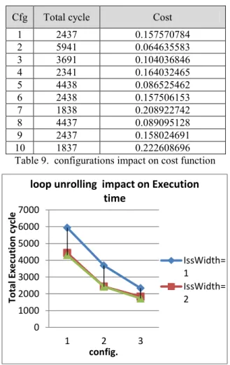
With increasing the IssueWidth and n1 parameter one can achieve lower total execution cycle. On the other hand we can see there is a trade off in choosing the best
configuration between configuration two and three.
These results are depicted in figure 2 and figure 3
[9,10].
Cfg Total cycle cycle Exec Stall cycle
1 2437 1778 659
2 5941 5032 909
3 3691 3032 659
4 2341 1832 509
5 4438 3529 909
6 2438 1779 659
7 1838 1329 509
8 4437 3528 909
9 2437 1778 659
10 1837 1328 509
Table 8. configurations impact on EXECUTION CYCLES
Cfg Total cycle Cost
1 2437 0.157570784
2 5941 0.064635583
3 3691 0.104036846
4 2341 0.164032465
5 4438 0.086525462
6 2438 0.157506153
7 1838 0.208922742
8 4437 0.089095128
9 2437 0.158024691
10 1837 0.222608696
Table 9. configurations impact on cost function
Fig. 3.Loop unrolling impact on Execution time
Explore and evaluation
For better finding the impacts of loop unrolling, we continued the increasing number of loop unrolling time
till 999 times. Fig. 4 shows the result of this
exploration which the exact execution time decreases
but the total execution time increase [6 – 10].
0 1000 2000 3000 4000 5000 6000 7000
1 2 3
To
tal E
xec
u
tion
c
yc
le
config.
loop unrolling impact on Execution
time
IssWidth= 1
108 We found that the increase in total execution time is due to increase in the I-cache memory miss rate which
generates stalls and add it to the execution time. Fig.5
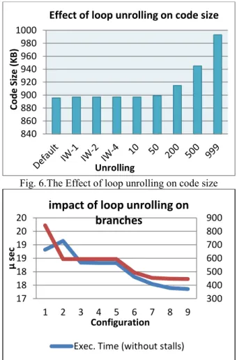
shows the impact of miss rate. It is really important which why the miss rate increase while increasing the loop unrolling amount? We will answer this question with a comparison on the code size generated by loop
unrolling factor. As you see in Fig 5 the code size
increases while the number of unrolling amount becomes bigger, because the loop body is being repeated [7].
Fig. 4.Loop unrolling impact on cost
3. DISCUSSION
In this experiment we tried to discuss on the subject of loop unrolling from different aspects including execution time, total execution time, code size, number of branches and etc. so for choosing the best unrolling amount we should consider these concerns and the
grate number of tradeoffs between them [8].
Another exploration on the result of generetaed logs, showd us that loop unrolling will reduce the number of branches and the overhead of checking condition for
each loop iteration. As depicted in Fig 6, loop unrolling
redues the number of branches so that it decrease the execution time.
Fig 5.The Extreme case for loop unrolling
Fig. 6.The Effect of loop unrolling on code size
Fig. 7.The Effect of loop unrolling on branches
SUMMARY AND CONCLUSION
In this computer assignment we became familiar with the impact of different compile time parameters on execution time of programs and benchmarks. It is really important to know that choosing the best parameters for code optimization faces different trade-offs which should be considered.
FUNDING/SUPPORT
Not mentioned any Funding/Support by authors.
ACKNOWLEDGMENT
Not mentioned.
AUTHORS CONTRIBUTION
This work was carried out in collaboration among all authors.
CONFLICT OF INTEREST
The author (s) declared no potential conflicts of interests with respect to the authorship and/or publication of this paper.
REFERENCES
1. Anjam F, Nadeem M, Wong S. Targeting code
diversity with run-time adjustable issue-slots in a chip multiprocessor. InDesign, Automation & Test 840 860 880 900 920 940 960 980 1000 Co d e S ize (K B ) Unrolling
Effect of loop unrolling on code size
300 400 500 600 700 800 900 17 18 18 19 19 20 20
1 2 3 4 5 6 7 8 9
µ
se
c
Configuration
impact of loop unrolling on
branches
Exec. Time (without stalls)
17 18 19 20 21 22 23 24 25 26 27 De fau lt IW-1 IW-2
IW-4 10 50
20 0 50 0 99 9 µ sec Unrolling
Unrolling Impact on Execution
time
Total Exec. Time 0 0.05 0.1 0.15 0.2 0.251 2 3
1 /to tal c yc le *c o d e si ze config.
Config. impact on size/total cycle
109 in Europe Conference & Exhibition (DATE), 2011
2011 Mar 14 (pp. 1-6). IEEE.[Scholar]
2. Brandon A, Wong S. Support for dynamic issue
width in VLIW processors using generic binaries. InDesign, Automation & Test in Europe Conference & Exhibition (DATE), 2013 2013 Mar
18 (pp. 827-832). IEEE.[Scholar]
3. Abadi M, Budiu M, Erlingsson Ú, Ligatti J.
Control-flow integrity principles, implementations,
and applications. ACM Transactions on
Information and System Security (TISSEC). 2009
Oct 1;13(1):4. [Scholar]
4. Aktas E, Ghose K. DARE: A framework for
dynamic authentication of remote executions. InComputer Security Applications Conference, 2008. ACSAC 2008. Annual 2008 Dec 8 (pp.
453-462). IEEE. [Scholar]
5. Arora D, Ravi S, Raghunathan A, Jha NK.
Hardware-assisted run-time monitoring for secure program execution on embedded processors. IEEE Transactions on Very Large Scale Integration (VLSI) Systems. 2006 Dec;14(12):1295-308..
[Scholar]
6. Payne A, Frow P. A strategic framework for
customer relationship management. Journal of
marketing. 2005 Oct 1;69(4):167-76.. [Scholar]
7. Rostamzadeh C, Canavero F, Kashefi F, Darbandi
M. Automotive AM-band radiated emission mitigation techniques, a practical approach. InElectromagnetic Compatibility (EMC), 2012 IEEE International Symposium on 2012 Aug 6
(pp. 162-166). IEEE. [Scholar]
8. Darbandi M, Shahbazi P, Setayesh S, Granmo OC.
New novel idea for Cloud Computing: How can we use Kalman filter in security of Cloud Computing. InApplication of Information and Communication Technologies (AICT), 2012 6th International Conference on 2012 Oct 17 (pp. 1-5).
IEEE. [Scholar]
9. Bletsch T, Jiang X, Freeh V. Mitigating
code-reuse attacks with control-flow locking.
InProceedings of the 27th Annual Computer Security Applications Conference 2011 Dec 5 (pp.
353-362). ACM. [Scholar]
10. Bletsch T, Jiang X, Freeh VW, Liang Z.
Jump-oriented programming: a new class of code-reuse attack. InProceedings of the 6th ACM Symposium on Information, Computer and Communications Security 2011 Mar 22 (pp. 30-40). ACM.