http://jpst.ripi.ir Journal of Petroleum Science and Technology 2019, 9(1), 28-43
ABSTRACT
In this paper, a system for efficient removal of carbon dioxide by hollow fiber membranes is proposed. The system is compact, and it is very useful for application in the offshore energy industries. In particular, it is used to removing CO2 from the exhaust of power generation facilities on offshore platforms.
The proposed dual membrane contactor contains two types of membranes (polypropylene membrane and silicone rubber membrane); moreover, the dual membrane contactor was designed and constructed for gas absorption processes. The module performance was evaluated based on permeation flux experiments. The experimental results were compared with the predictions from a numerical model developed in our previous studies. Furthermore, the mass transfer resistance in the fabricated module was investigated using resistance-in-series model. It is proposed that the computational techniques be used to develop design techniques in these kinds of complex systems. In addition, experimental methodologies have been used for the design and optimization of cross-flow hollow fiber membrane modules to absorb or desorb the gas. However, the experiments can be expensive and time consuming.
Numerical simulations used in conjunction with experiments can decrease the number of required experiments, thus reduce the required costs and time. In this work, a new modelling approach using computational fluid dynamics (CFD) is proposed to improve modelling flow within cross-flow membrane modules, and subsequently as a design means for such modules. In the CFD model, the fiber bundle is modeled as a porous medium to capture flow characteristics through the fiber bundle.
Also, mass transfer equations in the fiber and shell sides are coupled and solved using an iteration algorithm by taking consideration of the influence of flow behavior of both gas phase and liquid phase. In parallel, experimental study was also carried out to validate the results of computational modeling.
The CFD modeling results correlated well with the experimental data obtained from a lab scale cross-flow membrane module with uniform distributed fibers. The developed model was then used to examine the performance of modules with more complex geometries such as baffled modules and modules containing unevenly distributed fiber bundles. Finally, it was demonstrated that the CFD simulation is a promising approach in developing and optimizing cross-flow membrane module.
Keywords: Foam flooding, Low permeability, Heterogeneities. Majid Abedinzadegan Abdi*, Jing Jing Cai, and Kelly Hawboldt
Department of Process Engineering, Faculty of Engineering and Applied Science, Memorial University of Newfoundland, St. John’s, NL, Canada
CO
2Capture by Dual Hollow Fiber Membrane Systems
*Corresponding author Majid Abedinzadegan Abdi Email: mabdi@mun.ca Tel: +1 709 753 2461 Fax: +1 709 753 2461
Article history
Received: April 09, 2018
Received in revised form: August 03, 2018 Accepted: August 04, 2018
http://jpst.ripi.ir
Journal of Petroleum Science and Technology 2019, 9(1), 28-43
© 2019 Research Institute of Petroleum Industry (RIPI)
INTRODUCTION
Membrane based gas separation systems have been used in industries varying from petroleum to municipal water treatment. In addition, membrane systems offer the advantage of a high surface area to volume ratio, and therefore a relatively small equipment footprint. This combined with ease of operation make them particularly attractive for gas separations in remote and lightly manned or unmanned locations such as offshore oil and gas platforms. The ability to treat the produced gas to injection/fuel standards is limited due to the space restrictions on the platform. Most traditional gas treatment systems such as absorption contactors require a significant amount of space for equipment and chemical storage and use, and can be susceptible to the platform motion. Hollow fiber membrane contactors (HFMC) are used in gas treating due to high surface area per unit contactor volume, independent control of gas and liquid flow rates without any flooding, loading, weeping, foaming, or entrainment problems encountered in traditional absorber columns. HFMCs usually have smaller equipment footprints and require lower energy consumption than conventional absorption columns, which makes them particularly favored for offshore gas processing where space is limited. HFMCs can be operated under either cross flow mode or parallel flow mode, depending on the relative flow directions of both fluids. In general, cross flow membrane modules are favored because they can offer higher mass transfer coefficient, better shell side flow distribution and lower pressure drop compared to that of parallel flow modules. When the solvent is passed through shell side, the continuous splitting, and remixing of the liquid phase enhances the mass transfer coefficient,
which results in overall better performance. This paper summarizes many years of dual membrane contactor research at our laboratories at Memorial University of Newfoundland. The methodology used to approach the problem is briefly described with reference to our earlier publications and then the experimental systems are described in a few words. In addition, the modeling approach using analytical and computational fluid dynamics (CFD) approaches will be described. The most common approach to predict module mass transfer is to develop empirical. This approach is effective in predicting overall module performance but cannot provide information on concentration profile and local concentration driving force in the shell side. Moreover, a numerical model based on mass balance to describe the performance of a dual membrane cross flow module where the solvent flows on the shell side was developed [1]. One critical assumption made in this model is that the solvent is uniformly distributed throughout the shell, which limits its application to modules with simple geometries. In addition, the model cannot account for flow distribution in the shell, which has proved to be a critical factor affecting module performance. Hence, efforts are still needed in developing more rigorous models that can be used to predict shell side flow and performance of modules with complex geometries by taking consideration of the effect of module design on shell side flow pattern.
Journal of Petroleum Science and Technology2019, 9(1), 28-43 http://jpst.ripi.ir
equations to approximate the actual behavior. For modules containing thousands of fibres, it is impractical to discretize and model each individual fiber. The objective of this study is to develop a CFD modelling approach which can be used to predict mass transfer in cross flow modules for gas absorption. Modelling of the shell side flow takes consideration of the effect of module geometry by including membrane core, inlet, and outlet effects. The fiber bundle is treated as a porous medium in the CFD simulation for the shell side flow. An overall mass transfer coefficient correlation developed in previous work [1] is incorporated into the CFD model. Flow through the fiber is simulated in a separate CFD model. The two CFD models are solved using an iterative process (described below) to simulate mass transfer in the whole module. The combined CFD model was validated from experiments from a lab scale HFMC. The proposed modelling approach can be used as a tool for scale-up and design optimization of HFMC.
Dual Membrane Contactors
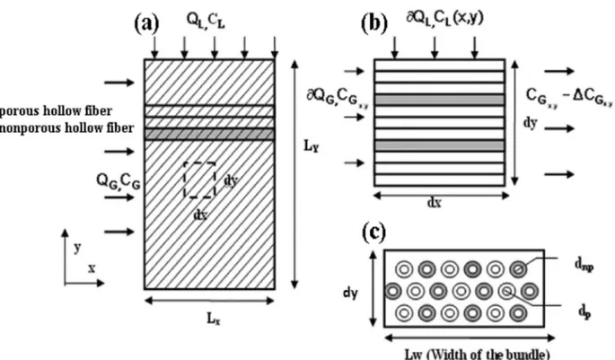
In the present study, two configurations of HFMC were investigated based on our previous studies[2]. The proposed modules comprise two types of hollow fibers. The porous hollow fibers containing feed gas are in the same contactor as nonporous fibers, which are used for solvent regeneration. An aqueous solution flows through shell side. In Module I (outlined in Figure 1-a), a low pressure is maintained on the permeate side of nonporous membrane. The differential pressure across nonporous membrane can improve contaminant removal from the solvent and partially regenerate the solvent stream simultaneously with the absorption process. This results in better
absorption efficiency. To further improve the removal efficiency, baffles are added in Module II (shown in Figure 1-b). Based on studies conducted by Wang and Cussler in 2003 [3], and those in heat exchanger, the baffles can improve mass transfer efficiency by minimizing shell-side bypass and providing a velocity component normal to the membrane surface.
Figure 1-a: Module I - Cross flow Dual HFMC.
Depending on the type of solvent, the absorption of contaminant can be either chemical or physical. Solutions of chemical solvents such as amines and alkali-metal salts are widely used in natural gas treating plants. However, regeneration of these chemical solvents is energy and space intensive and is unattractive for offshore platforms. Hence, this work mainly focuses on physical solvents. To analyze and predict the absorption performance of the proposed modules, a mathematical model has also been developed. A numerical model for liquid phase flowing in shell side was developed in this work to predict module performance. It takes impact of regeneration into consideration on absorption at the same time. The results were validated by previous experiment data from other researchers and published by our team [1]. Further, absorption performance of proposed
module for CO2 removal is compared with ordinary
http://jpst.ripi.ir
Journal of Petroleum Science and Technology 2019, 9(1), 28-43
© 2019 Research Institute of Petroleum Industry (RIPI)
EXPERIMENTAL PROCEDURES
Summary of Model Development
To model the performance of the dual membrane contactors a numerical model was developed to describe the mass transfer in the membrane, liquid phase and the gas phase. For details please refer to our paper [1]. The model is based on the following simplifying assumptions:
1. Contactor is operated under steady state and isothermal conditions.
2. Physical properties including diffusion coefficient, Henry’s constant, density, viscosity etc. are constant along the membrane.
3. No chemical reaction is involved, only physical mass transfer is modeled.
Figure 2: Cross section and modeling parameters in cross flow membrane contactor: (a) simplified module of cross flow dual HFMC, (b) side view of differential segment, and (c) front view of differential segment.
4. Membranes are under the non-wetted mode (gas-filled pores).
5. The pressure in gas phase is constant along the membrane.
6. The flow rate of fluid in the shell side is assumed to be steady through the contactor.
Overall Mass Transfer in Liquid Phase
Using the above assumptions, a material balance is applied on a differential segment of the module. In addition, the change of mass in liquid phase is due to loss of contaminant in gas in porous hollow fiber and gain of contaminant in the nonporous hollow fiber, it can be expressed as follows (as seen in Equation 1):
np G G L
L C Q C q
Q ∆ =∂ ∆ −∂
Journal of Petroleum Science and Technology2019, 9(1), 28-43 http://jpst.ripi.ir
By using the basic mass balance equations, the mass transfer in the liquid phase can be depicted by Equation 2:
0 0 0
= = =
∂ = − − −
∂ L X P G L X NP L X SNP
C M ( HC C ) M ( C C )
Y (2)
This expression can be solved as one of the boundary conditions on the gas side. The second boundary condition can be defined as:
i in
I L
L C
C = , ,at y = 0 (3)
Gas Phase Mass Balance with in Porous
Membrane
The transfer of contaminant molecules from gas phase to the liquid consists of three steps: transfer from bulk of the gas phase to the membrane, diffusion through the gas-filled pores, and transfer from membranes into bulk of the liquid phase. The mass transfer in the gas phase can be described by Equation 4:
0 0 = = ∂ = − ∂ in ,i
in ,i i i
G
y G L G y
C
M ( C HC )
x (4)
This expression is the boundary condition on the liquid side.
Gas Phase Mass Balance with Nonporous
Membranes
The contaminant absorbed in the liquid phase permeates the nonporous membrane through diffusion mechanism. The flux is proportional to partial pressure difference and inversely proportional to the membrane thickness:
∂ = per SNP −
NP out NP
NP
k C RT
q ( P ) d x
t H
π
∆
(5)where, Kper denotes nonporous permeability for
the gas contaminant and the membrane thickness
tNP is assumed to be small and therefore the
outer and inner surface areas are equal. Similar analysis is also applied to the baffled module, each
segment of Module I can be modeled by a set of partial differential equations. Moreover, the outlet concentrations of the previous segment in both gas and liquid phases are the initial and boundary conditions for the next segment.
In the gas phase, the concentration distribution of contaminant in the y direction is negligible compared to the liquid phase since the diffusion coefficient in gas phase is typically much larger than in the liquid phase. That is, the gas phase is completely mixed in y direction and the concentration profile of contaminant in the gas phase is a function of only x.
Model Validation
To validate the numerical model, the results were compared to the experimental data from Dindore et al in 2005 [4]. The module developed by Dindore differs from proposed module that the liquid solvent flows through the fibers and the mixture gas through the shell side and only one type of membrane is used. The model parameters were adjusted accordingly for comparison. However, it should be noted that the solution methodology remained the same.
Pure water was used as physical solvent to remove
CO2 from CO2/N2 mixture in the model validation
as this combination was used by Dindore et al in 2005 [4].
Our numerical model was modified to conform with the module proposed by Dindore et al in 2005:
G
G G L
C M ( HC C )
x
∂ = − −
∂ (6)
C
Gi
= C
Gin,i, for x = 0
(7)L
P G L
C M ( HC C ) y
∂ = −
∂ (8)
C
Lhttp://jpst.ripi.ir
Journal of Petroleum Science and Technology 2019, 9(1), 28-43
© 2019 Research Institute of Petroleum Industry (RIPI)
Absorption of CO2 with inlet concentration of
14.62 mol/m3 and 39.33 mol/m3 CO
2 at a constant
inlet gas flow rate of 2.21 x 10⁻⁴ m3/s were compared
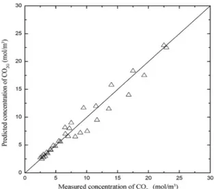
to experiment results from Dindore et al in 2005. Figures 3 and 4 compare the model data with the experimental data. The parity plots of measured
CO2 concentration in both gas outlet and liquid
outlet match well with the experiment data. The absorption of CO2 in both cases is relatively low due to the low gas residence time as a result of a high gas flow rate.
Figure 3: Parity plot of model results and the
experimental data of Dindore et al in 2005 for CO2
concentration at gas outlet (QG=2.21×10⁻⁴ m3/s).
Figure 4: Parity plot of model results and the
experimental data of Dindore et al in 2005 for CO2
concentration at liquid outlet (QG=2.21×10⁻⁴ m3/s).
All the analysis and predictions regarding the novel dual membrane contactor were based on mathematical models, and supporting experiments would be needed. Also, liquid velocity was assumed to be constant through the module, which is not the case in practice. Fluid dynamics of liquid flow in shell side and its impacts on mass transfer coefficients is in the next phase of this research. Moreover, it is planned by us to study this both computationally and experimentally.
Proving the basis of our modeling approach, it is attempted by us to build an experimental system to validate our modelling approach for a dual membrane system. There is an important tip that the previous experimental data belong to others and we had to simplify our model to verify the accuracy.
Fabrication and Assembly of Lab Scale
Dual Membrane Contactor
Journal of Petroleum Science and Technology2019, 9(1), 28-43 http://jpst.ripi.ir
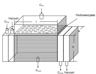
(a) (b)
Figure 5 (a): Schematic drawing of membrane core and arrangement of dual hollow fiber membranes in lab scale module; (b) Schematic drawing of dual membrane contactor.
The specification of the module is shown in Table 1.
Table 1: Specifications of lab scale dual membrane module.
Length (cm) Width(cm) Height(cm) Porous membraneArea (m2) Nonporous membrane area (m2) Voidage
10.3000 8.0000 8.0000 0.1800 0.0832 0.8500
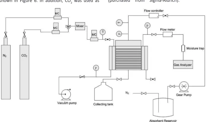
Experimental Set-up
The experimental set-up to evaluate the performance of dual membrane contactor is shown in Figure 6. In addition, CO2 was used as
the targeted component to be removed from a
gas stream of CO2/N2 mixture. Solvents tested
included distilled water and propylene carbonate (purchased from Sigma-Aldrich).
http://jpst.ripi.ir
Journal of Petroleum Science and Technology 2019, 9(1), 28-43
© 2019 Research Institute of Petroleum Industry (RIPI) In all experiments, the liquid phase was continuously fed into the shell side through a gear pressure pump and liquid flow rate was controlled by a digital mass flow controller.
Experiments were conducted in the fabricated
module for CO2 absorption where water was used
as the solvent. The feed gas contained 5% CO2 and
was passed through the tube side at a constant flow
rate of 1.63 L/min. A sweep gas of N2 flowed through
the nonporous fibers at a flowrate of 4 L/min. The CO2 concentration in the gas outlet was read off
through gas analyzer while CO2 concentration in
liquid phase was determined by titration using 0.4 M sodium hydroxide. Phenolphthalein was used as the indicator for the titration. The mass transfer
coefficient, Sherwood number (Sh), and Reynolds
number were then calculated accordingly using the known data of feed flow and module dimensions. Based on the results of experiments and calculated
values of Re and Sh numbers, it is proposed that the
following equation be used for predicting the mass transfer coefficient in a dual hollow fiber membrane system [5] :
Sh = 0.78 Re0.5226 Sc0.33 (9)
The relationship between Sherwood number and Reynolds number is a strong function of shell side flow and module geometry, which however should be independent of solvent selections and operation mode on the permeate side. To further confirm this assumption, experiments were carried out in this study by replacing water with propylene carbonate as solvent. Meanwhile, low vacuum was applied on the permeated side instead of sweeping gas with the vacuum pressure was maintained below 2 kPa. The Sherwood number derived based on experimental results were compared against
those calculated from the proposed correlation in the parity plot shown in Figure 7. It demonstrates that the proposed correlation can be used to predict the fiber side mass transfer coefficient in case of organic solvents. Moreover, it confirms that the Sherwood number indeed depends mainly on the module geometry of membrane contactor and independent of operation condition on permeation side.
Figure 7: Parity plots of Sherwood number received. Figure 8 compares mass transfer coefficients when two different solvent, water and propylene carbonate, were used and also demonstrates the effect of liquid flow rate on mass transfer. All the parameters and physical constants used in this study for calculation are given in Table 2.
Table 2: The parameters used in the model.
Parameter Value (Data for 298K) References
Water
Density (ρ) 995 kg/m3 Ref. [1,5]
Dynamic viscosity (ν) 1×10⁻⁶ kg/(m s) Ref. [1,5]
Henry’s constant (H) 0.82 (CL/ CG) (at
equilibrium) Ref. [1,5]
Diffusivity (D) 2×10⁻⁹ m2/s Ref. [1,5]
Propylene carbonate
Density (ρ) 1,210 kg/m3 Ref. [1,5]
Viscosity (ν) 2.5×10⁻⁶ kg/(m s) Ref. [1,5]
Henry’s constant (H) 3.5(CL/ CG) (at
equilibrium) Ref. [1,5]
Journal of Petroleum Science and Technology2019, 9(1), 28-43 http://jpst.ripi.ir
Figure 8: Mass transfer coefficient of dual hollow fiber membrane contactor for both solvents tested.
Afterward, a series of tests was started by us to confirm the validity of our modelling approach for dual membrane systems where absorption and partial regeneration of the solvent could occur simultaneously. The effect of operational conditions on module performance was investigated in the absorption of a
dilute gas mixture in which CO2 concentration in feed
gas was maintained at or below 5%. Absorption of concentrated gas and the effect of solute concentration on module performance were also studied in the following section. In these experiments, a feed gas
containing 5% CO2 was passed through porous fibers
at a constant flow rate of 1.63 L/min while a flow of N2
was passed through the non-porous fibers at a flow rate of 4 L/min. Through all testing, temperature was kept constant at 25 °C under atmospheric pressure. The effect of liquid and gas flow rates are shown in
Figures 9 to 11. In general, CO2 concentration in both
gas phase and liquid phase decreases as liquid velocity increases. This further confirms that the mass transfer strongly relies on the shell side flow. Better module performance is achieved when liquid phase passes through membrane core at a higher flow rate. The predictions from the proposed model were in a good agreement with experimental results in both phases.
Figure 9: Effect of liquid (water) flow rate on absorption flux. Overall, higher absorption flux was achieved when propylene carbonate was used rather than
water due to higher solubility of CO2 in propylene
carbonate than water. However, the effect of sweep gas stripping on overall absorption is not as pronounced as in the experiments using water. This is probably could be explained by the higher affinity of
propylene carbonate for CO2, which makes it difficult
for CO2 to be stripped out of the liquid phase. The improvement in module performance through solvent regeneration is not as significant as that in water.
Figure 10: Effect of liquid flow rate on absorption flux using propylene carbonate as solvent.
The effect of gas flow rate on absorption flux is summarized in Figure 11. The experiments were carried out using water as absorbent at a constant
Mass tr
ans
fer c
oe
ffcien
t k × 10
-5(m/
s)
Liquid flow rate × 10-6(m3/s)
Ab
sorp
tion Flux × 10
-5(mol/m
2/s
)
Liquid flow rate × 10-6(m3/s)
Ab
sorp
tion Flux × 10
-5(mol/m
2/s
)
http://jpst.ripi.ir
Journal of Petroleum Science and Technology 2019, 9(1), 28-43
© 2019 Research Institute of Petroleum Industry (RIPI) flow rate of 2×10⁻⁶ m3/s. A sweep gas of N
2 was passed
through nonporous fibres at a flow rate of 4 L/min. For comparison purposes, parallel experiments were also conducted without sweep gas. Gas flow rates were varied from 3.7×10⁻⁶ m3/s to 23.3×10⁻⁶ m3/s. The
CO2 concentration at the gas outlet decreased with increasing gas flow rate while the absorption flux almost stays constant. This further confirms that for physical absorption in liquid-gas membrane contactor, the transfer resistance lies mainly in liquid phase. The sweep gas improved flux by approximately 50%. The lower gas flow rates show better removal from the gas due to the longer gas residence time. However, it is worth mentioning that sweep gas degassing plays a more important role at higher gas flow rates. At a relatively low gas flow rate of 3.7×10⁻⁶m3/s, 26.9%
CO2 was removed with the sweep gas in comparison
with 19.3% without sweep gas, which improves the overall absorption efficiency by 39%. At a higher gas flow rate of 2.3×10⁻⁵m3/s, total removal efficiency
decreases in both cases due to reduced gas residence time in the module. By applying a sweep gas stripping, the removal efficiency was improved from 2.46% to 4.4%, improved by 78%. It implies that simultaneous degassing during absorption has a great potential in the case that operating flow rate is high.
Figure 11: Effect of gas flow rate on absorption flux using water as solvent.
The impact of other parameters on the performance of dual membrane contactors were also investigated and summarized in our publication [5].
In this work, an experimental study of a lab scale dual membrane module was carried out to investigate its performance over conventional membrane contactor and to validate the numerical model developed to simulate the system. The concept of dual membrane module was first proposed by Wang et al in 2006 [2], which was never been validated through experiment studies. In this study, a lab scale membrane contactor composed of polypropylene porous fibres and nonporous silicone rubber tubing was built, and its performance was demonstrated through removal
of CO2 out from N2/CO2 mixed gas. Empirical
correlations tailored for the proposed module was developed and the correlation was validated through experiments results. The mass transfer resistance in the designed module was also investigated using resistance in series model. The experimental results show that the resistance mainly comes from liquid film while the membrane resistance also contributes to 7% of the total resistance. Based on the results, mass transfer coefficient was quantified through correlation for the proposed module and the experiments were then further extended to
CO2 absorption along with simultaneous degassing
through nonporous membrane. Two operations were alternatively applied for degassing in nonporous membrane namely a sweep gas and a vacuum pressure. The experimental results were found in a good agreement with numerical modelling developed in previous work. In addition, it was
found that by stripping dissolved CO2 out from
liquid phase through nonporous membrane, absorption on the side of porous membrane can Liquid flow rate × 10-6(m3/s)
Ab
sorp
tion Flux × 10
-5(mol/m
2/s
Journal of Petroleum Science and Technology2019, 9(1), 28-43 http://jpst.ripi.ir
be effectively improved. The enhancement was especially significant for the application running at high gas flow rate. High liquid flow rate and vacuum pressure are the favored conditions for the contactor to achieve maximum performance. Finally, this work served to both validate our model and to test various operational conditions.
Numerical Study of Gas
Absorption-desorption in Dual Membrane Contactors
Using CFD Modeling
We had used CFD modelling for other applications very successfully and were aware that CFD modeling approach could be used as an effective design tool for optimization of membrane module design for gas absorption. Therefore, the modeling was adapted and tailored for gas absorption-desorption in the lab scale dual hollow fiber membrane contactor described previously. Since the dual membrane module is designed to be operated with solvent in shell side, CFD simulations can provide a better understanding of the liquid flow dynamics in the shell side. A CFD model is presented here which is then divided into two integrated simulations. In the first part of the CFD model, the flow distribution in the shell side is simulated by modelling the fiber bundle as a porous medium. Results from the shell side simulation are then fed to a CFD simulation of fiber side mass transfer. Then experiments of
CO2 absorption were undertaken in a lab scale
dual membrane contactor while the experimental results were compared with modeled results to verify the proposed model. The developed model was subsequently used as a design tool to study the performance of HFMC with more complex geometries such as baffled modules and modules containing unevenly distributed fibre bundles. The
results of the effort was published in our paper[1]. A summary of the modeling approach ad results will be presented here.
Model Development
In the proposed methodology, the following assumptions were made:
1. Steady state in both shell and fiber,
2. Each hollow fiber is assumed to have the same flow rate feed flow. The assumption was proven valid in the study of membrane oxygenator which shows the flow distribution in each hollow fiber is almost the same [19]; 3. In shell side, the fiber bundle was considered as a continuum (porous medium) where the gas phase was treated as source term in the governing equation and defined on per-unit total volume.
These assumptions will be discussed in detail below.
CFD Model for Shell Side
The cross-flow module used in our previous studies is shown in Figure 12.
Figure 12: Schematic drawing of lab scale module and a sample of meshed simulation field.
http://jpst.ripi.ir
Journal of Petroleum Science and Technology 2019, 9(1), 28-43
© 2019 Research Institute of Petroleum Industry (RIPI) flow regime; therefore, the velocity distribution of solvent in shell side can be described by the Navier Stokes equation.
CFD Model for Fiber Side Flow and Mass
Transfer
The arrangement of two types of fiber membrane is shown in Figure 13.
Figure 13: Schematic of fiber bundles in the shell side of cross flow dual membrane module.
The flow through porous and porous membrane is shown in Figure 14.
Figure 14: Schematic drawing of computational domain for fiber side in the cross flow dual membrane contactor.
The purpose of the model is not to simulate the non-porous membrane removal independently, but rather the impact of liquid flow dynamics on the removal rate. As such, to save computational time the liquid and non-porous fibers are grouped together as a sink term (see above).
Solution Methodologies and Computer
Algorithm
The computational domain of the lab scale cross flow module was generated using computer-aided design software (Workbench from ANSYS (Analysis Systems Software)). The computational domain is
then divided into a mesh. The resolution of the final mesh was determined varying grid resolutions (coarse to fine) to ascertain that the results were grid-independent and converged quickly. Fluent (v6.2.16, ANSYS, U.S.A.) was used to solve the governing transport equations. The equations describing shell side flow are solved first to calculate the distribution of velocity and concentration in the shell side. Since the initial concentration distribution in the gas phase is unknown, for the first iteration the concentration in the gas phase is assumed to be constant along the length of the fiber and equal to the inlet concentration. In addition, the velocity and concentrations obtained from shell side CFD model were used as input to the fiber side CFD model. The fiber side CFD model was then run and updated gas concentration profiles in the fibers side (CG). The results were fed back to the shell CFD model to generate updated concentrations in the liquid. This process was repeated until the gas concentration in the liquid and gas phase converge.
Experimental Validation of CFD Model
Experiments were carried out in our lab scale module
for CO2 removal from a gas mixture of N2/CO2 using
water as solvent. Two sets of experiments were carried out using gas mixtures containing 5% and 30%
CO2 respectively. The experimental results were
compared with the simulation results from CFD
analysis in terms of CO2 concentration at gas outlet
Journal of Petroleum Science and Technology2019, 9(1), 28-43 http://jpst.ripi.ir
Figure 15: A comparison of modelled results with
experimental measurement (CO2in% = 5%, Qg= 5.6×10⁻⁶ m3/s).
In cross flow mode, the CO2 concentration not only
varies along the fiber length, but also varies with the module height. Therefore, the concentration in Figure 15 is an averaged concentration at the gas outlet. The CFD model was further verified by comparing the modelled results for absorption operated under different gas flow rates. In addition,
CO2 concentration in feed gas was kept constant at
5%. The CO2 concentration from experiments at
gas outlet and liquid outlet are compared with CFD model results in Figures 16 and 17 respectively. The predicted concentration in both phases is in a good agreement with experimental results. These two plots further validate the CFD model.
Figure 16: Comparison of CO2 at gas outlet between
experiment and CFD model (CO2in 5%, QL was varied
from 10-6 m3/s to 8.33×10⁻⁶ m3/s).
Figure 17: Comparison of CO2 at liquid outlet between
experiment and CFD model. CO2in 5%, QL was varied
from 10-6 m3/s to 8.33×10⁻⁶ m3/s).
The distribution of velocity and concentration is important with respect to scale up and optimization.
A cross sectional view of CO2 concentration
distribution predicted by the CFD model through the fiber bundle along the centerline is shown in
Figure 18 for a liquid flow rate of 6.6 ×10⁻⁶ m3/s.
The concentration profile is not uniform as the concentration in the center is lower than at the module boundary, which is mainly caused by the entrance effect. This is not unexpected; however, the question is this effect module performance, as these effects would only be enhanced with scale-up. The following sections investigate these effects.
Figure 18: CO2 concentration distribution (mol/m3) in
porous media (fiber bundles) (CO2in 30%, QL=6.6 ×10⁻⁶ m3/s,
QG=5.6×10⁻⁶ m3/s).
CFD Application to Design
http://jpst.ripi.ir
Journal of Petroleum Science and Technology 2019, 9(1), 28-43
© 2019 Research Institute of Petroleum Industry (RIPI) distribution and hence improve module performance is to add baffles into the shell side.
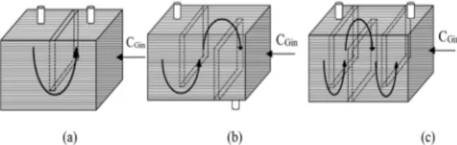
Modules with different numbers of baffle were modeled (shown in Figure 19). These models have the same specification as the un-baffled lab scale module. The thickness of the fiber is 1 mm.
Figure 19: Schematic of baffled modules (a) module with 1 baffle; (b) module with 2 baffles; (c) module with 3 baffles.
The CFD model was used to simulate the baffled
modules with CO2- N2 mixed gas containing 30%
CO2 using water as solvent. The gas flow rate was
kept constant at 1.8×10⁻⁵ m3/s while the solvent
flow rate was varied from 1.4×10⁻⁶ m3/s to 2.8×10⁻⁵
m3/s. The effect of baffles on module performance
is shown in Figure 20 by varying the numbers of baffles in the module. In general, the absorption flux is improved as the number of baffles increases in the shell side. At higher flow rates, the enhancement of performance due to the baffles is more pronounced than that at lower flow rates.
Figure 20: Effect of baffle numbers on absorption flux
(CO2in 30%, QG=5.6×10⁻⁶m3/s).
Adding more baffles adds cost to modules; therefore; there is a balance between enhanced performance and expense. Figure 21 summarizes the impact of number of baffles on performance
for a feed gas containing 30% and 100% CO2
respectively while the gas flow rate and liquid flow rate was kept at 5.6×10⁻⁶ m3/s and 5.6×10⁻⁶
m3/s respectively. Overall, the absorption flux
for absorption of concentrated gas (100% CO2) is
higher than absorption of dilute gas (30% CO2), due
to the higher concentration gradient. However, the effect of baffles on module performance is less significant for dilute gas systems.
Figure 21: Effect of solute concentration on the
performance of baffled module for CO2 absorption
(QG=5.6×10⁻⁶ m3/s, Q
L=5.6×10⁻⁶ m3/s).
Effect of Fiber Arrangement on Mass
Transfer
One critical design parameter in HFMC is the distance between fibers and the fiber arrangement. For loosely packed modules, fibres can be potted one by one and therefore achieve uniform fiber distribution (i.e. equal distance between each fiber). However, fibers are usually non-uniformly distributed in tightly packed modules. To study the effect of fiber distribution, a constant local (and overall) packing density was compared with
Absorption Flux × 10
-4(mol/m/s)
Absorption Flux × 10
Journal of Petroleum Science and Technology2019, 9(1), 28-43 http://jpst.ripi.ir
the module with varied local packing density. To achieve variable local packing density the CFD model membrane core was divided into three sections with different local packing densities (8%, 13%, and 20%). The overall packing density was 15% for both cases. Also, the feed gas flow rate
was kept constant at 5.6×10⁻⁶m3/s, and liquid flow
rate varied from 1.33 ×10⁻⁵ to 1.6×10⁻⁴ m3/s. Figure
22 outlines the results. The cross flow module with variable local packing densities did not perform as well in comparison with a module with uniform packing density.
Figure 22: Effect of non-uniform fibre distribution on
CO2 absorption flux in cross flow module (CO2% in feed
gas=30%, QG=5.6×10⁻⁶ m3/s).
CONCLUSIONS
In this work, a summary of our research in the use of a novel dual membrane contactor system was presented. The systems are compact and perform superior as compared to other types of liquid gas contact devices given the advantage that the solvent is partially or fully regenerated in the system, and therefore the mass transfer performance is significantly improved. Different modelling approaches were adopted to predict the performance of the system. Experimental systems were designed and fabricated to validate
our modelling approach. The agreement between the experimental tests and our modelling results were very satisfactory, however optimizing the performance and improving the design required more complicated modelling approaches. Modern design techniques including a CFD model were developed as design and optimization tools. The CFD model was developed to incorporate the shell side flow distribution into the overall model. In the shell side, the fibre bundles were treated as porous medium to avoid the discretization of computational geometry for each single fibre. As a result, the flow field and shell side mixing which are a strong function of module design and flow dynamics can be reflected. The proposed CFD model was validated through experiments using a dual membrane contactor of bench scale size. It was then used to study various design parameters for HFMC. The velocity and concentration distribution in cross flow module shows that the velocity in the center of the fiber bundle is much higher than the boundary. This is not unexpected, however, the CFD model gives one tool to determine the extent of the impact and vary design accordingly. An analysis of adding baffles showed that baffles enhance mass transfer. The impact of fiber arrangement on module performance was also studied through CFD analysis. The result confirmed that mass transfer is a strong function of shell side flow distribution. Modules with more evenly distributed fiber bundles tend to result in better performance.
We believe that this system is a more suitable
contactor system for CO2 capture applications in
offshore industries where the footprint area and real estate is at premium.
http://jpst.ripi.ir
Journal of Petroleum Science and Technology 2019, 9(1), 28-43
© 2019 Research Institute of Petroleum Industry (RIPI)
NOMENCLATURES
CFD : Computational Fluid Dynamics ANSYS : Analysis Systems Software
REFERENCES
1. Cai J., Hawboldt K., and Abedinzadegan Abdi M., “Contaminant Removal from Natural Gas Using Dual Hollow Fiber Membrane
Contactors,” Journal of Membrane Science,
397–398, 2012, 9-16.
2. Wang S. Y., Hawboldt K., and Abdi M., “Novel Dual-Membrane Gas-Liquid Contactors: Modeling
and Concept Analysis,” Industrial and Engineering
Chemistry Research, 2006, 45, 7882-789.
3. Wang K. L. and Cussler E.L., “Baffled Membrane
Modules Made with Hollow Fiber Fabric,” Journal
of Membrane Science, 2003, 85, 265-278. 4. Dindore V. Y., Brilman D. W. F., and Versteeg G. F.,
“Modelling of Cross-flow Membrane Contactors:
Physical Mass Transfer Processes,” Journal of
Membrane Science, 2005, 251, 209-222
5. Cai J, Hawboldt K., and Abedinzadegan Abdi M., “Improving Gas Absorption Efficiency Using a
Novel Dual Membrane,” Journal of Membrane