Resolution Utilization of Arbitrary Displays
Taimur Khan, Daniel Schneider, Yasmin I. Al-Zokari, Dirk Zeckzer,
and Hans Hagen
11 University of Kaiserslautern
67653 Kaiserslautern, Germany
{tkhan,d_schnei,alzokari,zeckzer,hagen}@informatik.uni-kl.de
Abstract
Scalable large high-resolution displays such as tiled displays are imperative for the visualization of large and complex datasets. In recent times, the relatively low costs for setting up large display systems have led to an highly increased usage of such devices. However, it is equally vital to optimally utilize their size and resolution to effectively explore such data through a combination of diverse visualizations, views, and interaction mechanisms. In this paper, we present a lightweight dispatcher framework which facilitates input management, focus management, and the execution of several interrelated yet independent visualizations. The approach is deliberately kept flexible to not only tackle different hardware configurations but also the amount of visualization applications to be implemented. This is demonstrated through a scenario that executes four interrelated visualizations equally well on both a 5 PC tiled-wall and a single desktop. The key contribution of this work is the ability to extend the tiled-wall to work with multiple applications for enhanced size and resolution utilization of such displays.
1998 ACM Subject Classification I.3 Computer graphics, I.3.3 Picture and Image Generation Keywords and phrases Large and High res Displays, Coordinated and Multiple Views, Human
Computer Interaction
Digital Object Identifier 10.4230/DFU.Vol2.SciViz.2011.144
1
Introduction
Innovations in large wall-sized displays have been yielding benefits to visualizations in industry and academia: to cater to a larger audience, for more efficient collaborative work, to further immerse the client in virtual reality applications, and to facilitate the visualization of large and complex datasets by maintaining both overview and detail views simultaneously [5]. It is these improvements that have led to the growth of large display implementations despite the limitations in size of a single such display and the costs associated with them. The single most influential factor in this progression has been the advent of tiled display systems - a large display consisting of tiled smaller ones driven by clusters of off-the-shelf PC systems. This leads to complete physical scalability over the eventual size of the display while keeping the costs relatively low. These facts have led to a number of research projects that have incorporated tiled displays and made it amongst the top ten visualization research topics in recent times [15].
Effective exploration of truly large complex datasets is a quandary that researchers are constantly trying to tackle in a number of domains. In the recent past various solutions have been employed including multiple views, data aggregation, and filter techniques. There is no single solution to this problem, as it varies depending on the nature of the domain,
© Taimur Khan, Daniel Schneider, Yasmin I. Al-Zokari, Dirk Zeckzer, and Hans Hagen; licensed under Creative Commons License NC-ND
Scientific Visualization: Interactions, Features, Metaphors.Dagstuhl Follow-Ups, Vol. 2. Editor: Hans Hagen; pp. 144–159
Dagstuhl Publishing
the dataset, and the experts involved. However, the work presented in this paper proposes the use of coordinated multiple applications / views on tiled-wall displays as a means to efficiently explore such datasets irrespective of the domain. The core idea is to divide the tiled-wall into a large work area that utilizes a distributed rendering framework and several other subsections that run coordinated applications. The emphasis of this work has been on the management of different concurrent applications running on a tiled-wall through a dispatcher framework that handles coordination and input management.
There are a number of tiled-display rendering frameworks available that vary in their sophistication and as a consequence in their complexity and functionality as well [16, 22]. However, these choices were significantly reduced while imposing the following requisites: to hide the display setup from the developer, to have the flexibility to execute on several display configurations, and to keep the implementation relatively simple. These rationales assisted us in choosing TileRenderer [5] as an appropriate rendering framework, as the other frameworks examined (CAVELib [14], VRjuggler [3], Syzygy [19], Jinx [21], Chromium [9], NAVER [11], and CGLX [6]) were quite heavy-weight with extensive APIs. The common theme amongst the frameworks mentioned is that they provide extensive libraries for interactions, interfaces, and virtual contents for virtual reality environments. It is due to the various libraries required and the sheer quantity of modules involved that makes their usage highly complex and heavy-weight. In comparison, Deller et al. formed TileRenderer with a small and easy to use library that allows developers to shape or alter existing OpenGL applications through the use of a few callback functions.
TileRenderer much like most existing such frameworks distributes the geometry and material data to render a single applications graphics database on multiple rendering clients while we aim to tackle multiple applications. This left three vital tasks for our dispatcher framework to perform: inter-application communication, interaction, and focus management. The only other viable solution would be to have a single scene with various viewports; however, we choose to refrain from this approach to eliminate the possibility of artifacts from one model appearing in the background of another and to a larger extent due to the interaction limitations within these viewports.
The organization of this paper is as follows: examine related work (Section 2), discuss the proposed dispatcher framework (Section 3), demonstrate it using a visualization case study (Section 4), and lastly look at possible future work (Section 5). In the case study, a visualization scenario is presented on two distinct hardware configurations that utilizes our framework in order to execute four visualization applications simultaneously, handle interactions between them, and manage input and focus remotely.
2
Related Work
In order to obtain a working prototype of the dispatcher framework, the following issue needed to be addressed: distribute and synchronize input devices and applications over the network. In this section, software solutions aimed at distributing input devices and applications are examined for comparison.
2.1
Distributed Device Data
In the related context of collaborative environments, co-located and synchronous interactions lead to a query of how a specific form of input supports an application realized on a shared display [8]. APIs such as CAVELib [14], Syzygy [19], and VR Juggler [3] have embedded support for collaborative interaction between remote applications. In the case of the latter,
this is in the form of a module called Gadgeteer, which distributes device data across machines and clusters.
Instead of integrating such a heavy-weight architecture, producing our own streamlined mechanism was preferred: switching thevirtual focus and passing encoded/decoded Simple DirectMedia Layer (SDL) [20] messages - see Section 3.4.
2.2
Distributed Applications
There are a few standards or technologies that are designed towards application integration. Common Object Request Broker Architecture (CORBA) was a revelation in allowing devel-opers to undertake distributed object-oriented programming to integrate diverse applications into heterogeneous distributed systems [24]. Similarly, the High Level Architecture (HLA) [4] has been instrumental in linking disparate simulations. Such frameworks provide rich func-tionality at the expense of API complexity, so we crafted our own method: each application registering for a message type with the dispatcher and processing it accordingly.
3
Framework Overview
The dispatcher framework presented in this paper works in conjunction with TileRenderer, however, it can be quite easily ported to any distributed rendering software such as the ones mentioned in Section 1.
First, TileRenderer was modified to work with Coin3D [12], an open source Open Inventor API, instead of pure OpenGL. With the incorporation of scene graphs the environment immediately improved significantly, providing two distinct advantages:
1. Improved rendering performance and optimal use of available hardware resources. Scene
graphs by nature maintain a "retained" model of the virtual world allowing additional optimizations such as processing culling and drawing in parallel, and state sorting [18].
2. Introducing a high-level programming interface to eliminate low-level OpenGL commands
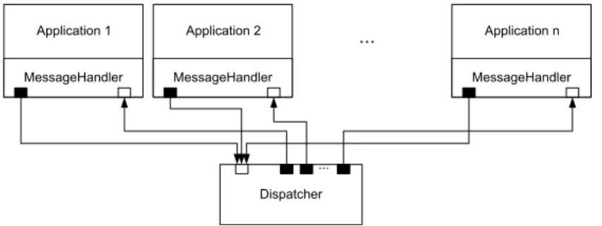
such as primitive drawing commands, state settings, and matrix manipulations [18]. The next vital step towards our goal of enhanced tiled wall utilization required the ability to handle multiple applications. This led to the development of the dispatcher framework that is explored further in the next sections. Its main functionality is to act as a centralized message center where all messages are received and forwarded as needed. The main components of this framework are depicted in the figure below and described thereafter.
NetMessages (see Section 3.1) are created by the applications and connected to the Dispatcher via theMessageHandler (see Section 3.3).
Individual applications register for a message type at theDispatcher (see Section 3.2). Appropriate messages are forwarded by theDispatcheronly to the subscribers (see Section 3.2).
Input is fed directly to the application running TileRenderer, for all others we incorporate the concept ofVirtual Input - a special type of message that is an encoded SDL event (see Section 3.4).
Figure 1 depicts the logical system structure of the dispatcher framework. The developer may add several disjoint applications to the framework, however these applications need to interface with the commonMessageHandler for both interaction and communication purposes. It is through the MessageHandler that the different applications are able to communicate with theDispatcher. Here, a particular communiqué is worth mentioning:
MessageHandler Application 1 MessageHandler Application n MessageHandler Application 2 Dispatcher ... ...
Figure 1Logical System Structure.
encoded SDL events that are used to pass thevirtual focus, hence providing the ability to interact with applications that may be running on a remote PC.
A centralized message center that is referred to as the Dispatcher is responsible for receiving and forwarding messages if necessary. The communication itself is realized by using sockets that are represented as black and white boxes in Figure 1. The distinction here is in the communication direction: a black box stands for an output socket while a white box stands for an input socket.
3.1
NetMessage
To be able to distinguish between differentNetMessages, enumerated message types are used. Alternatively, one might have encoded the message type in the text message itself leading to a more complex process. Depending on the type of message, the processing of the message text varies:
INVALID: An invalid message can not be processed. Non-blocking socket reading may return NULL, if there is no value to read. To avoid NULL references, this type is introduced.
DISPATCHER_REGISTRATION: To take part in the communication process, the applications have to register at the Dispatcher by using this type of message.
DISPATCHER_MESSAGE_SUBSCRIPTION: To be informed when a certain type of message is received at the Dispatcher, a client has to subscribe for it. This is done to avoid passing all messages to all the clients - flooding.
DISPATCHER_VIRTUALFOCUSCHANGE: To force a change in which application has the virtual focus, this type of message has to be sent.
VIRTUALFOCUS_RECEIVED: If an application receives this type of message, it has received the virtual focus. In case ofTileRendererthis implies processing theSDL_Events captured by the input devices locally.
VIRTUALFOCUS_LOST: If an application receives this type of message, it has lost the virtual focus. In case ofTileRenderer this means to forward theSDL_Events captured by the input devices to the Dispatcher.
SDLEVENT: This type of message signals that an SDL_Event is encoded in the NetMessage. This is described further in Section 3.4.
QUIT: An application has to finish its current task and shut down.
There are a number of other application specific messages that can be added to exchange specific information as required by the developer, examples of these are presented later in the case study.
3.2
Dispatcher
In this section, we examine the logical structure of theDispatcher (see Figure 2a) and the flow of its main loop (see Figure 2b). TheDispacherThread is at the heart of the logical structure: it periodically invokes the main loop, polls theInputSocket, and maintains the VirtualFocus and theRegistry.
TheDispatcherThread is an asynchronous thread that implements a non-blocking read by continuously polling theInputSocket for an encoded character stream. This encoded stream is used to fill aNetMessage data structure, where a key field is the enumerated message type that determines how to process such a message. If the received message is of type INVALID this means there is no data available and the nextNetMessage is polled. This action continues until there is valid data available on the socket - any message that is not of typeINVALID.
As soon as a valid message is received, it is checked at theRegistry whether there are subscribers for this type of message. If this is the case, theNetMessageis forwarded via the OutputSocket of the corresponding registry entry. Depending on the message type, further
processing may be required:
DISPATCHER_REGISTRATION: If the received message is of this type, a new applica-tion has to be registered. This is accomplished through a new applicaapplica-tion entry created at theRegistry that contains theOutputSocket connection to the remote application. DISPATCHER_MESSAGE_SUBSCRIPTION: If such a message is received, it implies that an application has subscribed for a new type of message at theDispatcher. Whenever a message with the corresponding type is received by theDispatcher, it will be forwarded to all its subscribers.
DISPATCHER_VIRTUALFOCUSCHANGE: This type of message forces thevirtual focusto switch to another application. The switching process is faciliated by the Virtual-FocusServer, responsible for the release of thevirtual focusfrom the previous application and for setting it to a new one. In other words, input device data captured by SDL is forwarded to the appropriate subscribing application.
QUIT: If a message of typeQUITis received, it is distributed to all registered applications in order to initiate their respective shutdown.
If some other type of message is received by the Dispatcher, it is simply ignored as it holds no significance for theDispatcher itself.
3.3
MessageHandler
It has been shown earlier in Figure 1 that all applications or views use theMessageHandler component to communicate with theDispatcher. Here it is important to note that the current configuration utilizes TCP for both input and output sockets, thus ensuring that events are received in the same order as they occur. In this section we shall further examine the logical structure of theMessageHandler as shown in Figure 3a and the typical behavior of a view as in Figure 3b.
When a new application or view starts up, it initializes the MessageHandler. It is theMessageHandler that communicates backwards to the registered applications or views, through the use of callbacks. Thus, the first step is to register all callbacks at the Message-Handler, which in turn registers itself automatically for the corresponding message types at theDispatcher. Once these callbacks are registered, both theInputThread as well as the OutputThread are started.
polls NetMessages periodically maintains Registry DispatcherThread VirtualFocus Server uses InputSocket Dispatcher Application pushes NetMessages OutputSocket pushes NetMessages
(a)Logical structure of the Dispatcher
Dispatcher Poll Message [type == INVALID] Forward message to all subscribers [type == DISPATCHER_ REGISTRATION] [type == DISPATCHER_ MESSAGE_ SUBSCRIPTION]
Add an entry for the Application at the Registry true
Add a subscription for the Application for a given message type true
[type == DISPATCHER_ VIRTUALFOCUS
CHANGE]
Release virtual focus from previously focussed Application true
Set virtual focus to new Application [type == QUIT] Quit Dispatcher true false true false
(b)Main loop of the Dispatcher
Figure 2Structure and flow of the Dispatcher.
The original thread continues with the execution of the applications main program loop. While this program loop is in operation, someNetMessagesmay be put into the SendQueue. Similarly, the InputThread continuously receives messages in a non-blocking way. Much like the dispatcher functionality described in Section 3.2, as long as no valid messages are received theInputThread simply waits. On the other hand, a valid message is pushed to the CallbackManager as soon as it is received. If there are callbacks registered for this type of message, the corresponding callback function is executed.
The VirtualFocusClient registers callbacks at the CallbackManager by default when it starts up. Further, if a received message is of the type VirtualFocusChange then the VirtualFocusClientis called and the virtual focus is handled automatically - by either grabbing or releasing the virtual focus in question.
The OutputThread continuously polls theSendQueue. If there are messages available, they are pushed to theOutputSocket and transmitted.
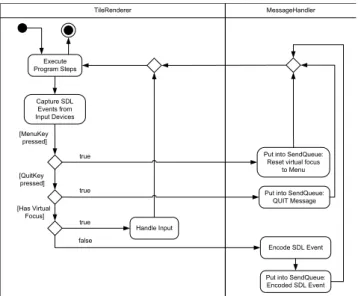
Input devices are physically connected only to theTileRenderer application, the extension point in Figure 3b for this application is refined further in Figure 4. The TileRenderer based application continuously captures input data from all its connected input devices as SDL_Events. If anSDL_Event representing a special menu key is pressed, a message is put into theSendQueue to switch the focus to theMenu View. If theSDL_Event represents the
Application
pushes NetMessages calls
pushes NetMessages Callback Manager InputThread SendQueue VirtualFocus Client InputSocket OutputSocket MessageHandler polls NetMessages maintains polls NetMessages pushes NetMessages OutputThread initializes and
starts threads registers
(a)Logical structure of the MessageHandler
Initialize
MessageHandler Application
Start up Register Callbacks
Receive NetMessage Send NetMessage Start InputThread and OutputThread Put NetMessage into SendQueue Execute callback functions [received a message] Program Loop Extension Point
(b)Typical behavior of a view during runtime
Figure 3Structure and behavior of the MessageHandler.
special quit key, in this case the ESC key, a message of typeQuitis put into theSendQueue. If theTileRendererholds the virtual focus, it processes theseSDL_Eventslocally. Alternatively, if it does not hold the virtual focus then theSDL_Events are encoded and put into the SendQueue, so that the remote application with the virtual focus can process it.
3.4
Virtual Input: Encoding/Decoding of SDL Events
The structure of anSDL_Event is shown in Figure 5. This is a streamlined structure as only theSDL_Event types which are used by our system are listed, further general SDL details are found on their Wiki documentation [20]. It is prominent from the above-mentioned diagram that eachSDL_Event type has its own specific structure:
SDL_MouseButtonEvent: this SDL event type signalizes a mouse button event and is followed by the fields: button, state, x, and y. These fields encode the following information: buttonencodes the mouse button index,stateis either set toSDL_PRESSED or SDL_RELEASED indicating if the button is pressed or released, x holds the x coordinate relative to the window, andy holds the y coordinate relative to the window. SDL_MouseMotionEvent: this field signalizes a mouse motion event and is followed by the fields: state, x,y, xrel, andyrel. These fields encode the following information: for state,x, andy refer above, whereasxrel andyrel hold the relative motion in the x and y screen directions respectively.
TileRenderer Execute Program Steps [MenuKey pressed] [QuitKey pressed]
Put into SendQueue: Reset virtual focus
to Menu true Handle Input Capture SDL Events from Input Devices
Put into SendQueue: QUIT Message true [Has Virtual Focus] true Encode SDL Event
Put into SendQueue: Encoded SDL Event false
MessageHandler
Figure 4Local and remote processing of SDL_Events.
SDL_MouseButtonEvent SDL_MouseMotionEvent SDL_UserEvent
SDL_KeyboardEvent
scancode: Uint8 sym: SDLKey mod: SDLMod unicode: Uint16
SDL Event Type Name
SDL Event Type Structure
button: Uint8 state: Uint8 x: Uint16 y: Uint16 state: Uint8 x: Uint16 y: Uint16 xrel: Sint16 yrel: Sint16
code: int data1: void* data2: void*
state: Uint8 keysym: SDL_keysym
Figure 5Structure of an SDL_Event.
SDL_UserEvent: this field refers to a user defined input device and is followed by the fields: code, data1, anddata2. These fields encode the following information: codeis a user defined event code, whereas data1 anddata2 are user defined data pointers that may be utilized as required.
SDL_KeyboardEvent: this field refers to a keyboard event and is followed by the fields: state andSDL_keysym. The state field can hold either the valueSDL_PRESSED or SDL_RELEASED indicating if a key is pressed or released. TheSDL_keysymstructure on the other hand is composed of several further fields: scancode,sym,mod, andunicode. Thescancodefield is normally not utilized; it contains a hardware-dependent scan-code returned by the keyboard. The sym field is the SDL-defined constant that represents the selected key and is often used while programming to inquire if a certain key has been pressed or released. The field mod stores the current state of the keyboard modifiers and unicodestores the unicode character corresponding to the key if it is enabled.
In the case ofTileRenderer having virtual focus, these SDL events are processed locally. On the other hand, when another application has the virtual focus we encode these SDL events into a character string and send them to that application via theDispatcher. It is possible to encode and then later decode these SDL events as knowledge of its datastructure is known beforehand. Once decoded, a new SDL event is created with the received values and pushed into the SDL event queue of the receiving application, hence the concept of
Virtual Input. The only exception to the above process was theSDL_UserEvent, where data1 and data2 are user defined data pointers. In our scenario (see Section 4), a space mouse was added as a user defined device. Here, knowledge of theRotation andTranslation datastructures utilized by the space mouse handler assisted in encoding and decodingdata1 anddata2 respectively.
4
Case Study: Safety and Security Analysis using CakES
The framework presented in this paper has been used to produce a safety visualization called CakES [1] that was designed to assist software engineers in the safety and security of embedded systems. This visualization system consists of multiple applications or views that visualize the physical model, the minimal cutsets, and the basic events of the fault tree. Our framework facilitates interaction amongst these different views, allowing the user to have different levels of focus and context simultaneously.
A brief introduction to these safety analysis topics is listed below with references for further readings:
Fault Trees (FTs)are tools in system safety, reliability, and availability studies [13]. Basic Events (BEs)are the lowest-level influence factors in theFT and they are repre-sented as the leaves. The hazard that is examined in the fault tree is called thetop event which is at its root [10].
Minimal Cut Sets (MCSs)are unique combinations of BEsthat can cause the top event to occur [2].
In addition to theNetMessages described in section 3.1, the following application specific messages were added to the framework:
MCS_SELECTION: A minimal cut set was selected.
MCS_BE_PROBABILITY: A basic event’s probability is sent. HOLDER_BOUNDS_CHANGED: Min and Max bounds changed. HOLDER_VALUES_CHANGED: Value of a holder changed.
4.1
Multiple Applications
The CakES system utilizes four distinct applications or views interconnected through the framework presented in this paper. The reason to employ these views as independent applications is two-folds: 1) give programming freedom to the developer, and 2) avoid different viewports in the same scene to avoid artifacts and interaction limitations. These views are described further in the following subsections.
4.1.1
Menu View
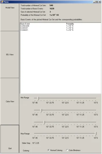
The menu (see Figure 6) functions as the primary interface between the other views that are discussed further in Sections 4.1.2, 4.1.3, and 4.1.4. It allows the user to switch the virtual focus between these different views. Additionally, it displays vital statistical data about the selectedMCS: size, probability, and details of itsBEs. Further, the user may reorganize the MCSsin theMCS Viewaccording to his preferred criteria by using either the sliders or radio buttons provided.
Figure 6Menu View.
4.1.2
Model View
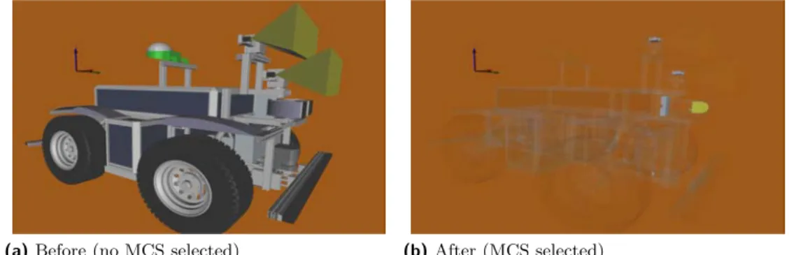
This view is employed to exhibit the physical parts of the RAVON model as shown in Figure 7a. The model depicted is of the Robot RAVON (Robust Autonomous Vehicle for Off-road Navigation); further details can be found on the AG Robotersysteme website [17]. The TileRenderer application drives this view as it is to be displayed on a stereo monitor in the configuration described in Section 4.2.1 and on the larger area of the tiled wall as in the configuration described in Section 4.2.2. Interaction mechanisms that allow the user to explore the model further are zooming, rotation, and translation. Further, it utilizes the framework by registering for anMCS_SELECTION, so that once anMCS is selected in the MCS View (see Section 4.1.3) appropriate data is received. As a consequence of this data exchange, the RAVON model is rendered transparent and the relevant BEs are rendered opaque (see Figure 7b).
4.1.3
MCS View
This view uses a Cake metaphor [1] to visualize theMCSs, their probabilities, and their BEs (see Figure 8). A text file containing information about theBE distribution is generated
(a)Before (no MCS selected) (b)After (MCS selected)
Figure 7Model View: Before and after receiving MCS data through Dispatcher.
(a)Before Virtual Picking (b)After Virtual Picking
Figure 8MCS View: Before and after Virtual picking.
using theESSaReltool [7] and is used in the intial formation of the Cake (see Figure 8a). The Cake consists of three separate levels depicted by red, yellow, and blue cylinders. Each cylinder represents anMCS and within eachMCS there are a certain number ofBEs. These three levels correspond to a range of fault probabilities that may also be adjusted via the Menu sliders. Further, each level uses saturation to distinguish between probabilities that lie in the same range.
The user is provided interaction mechanisms quite similar to theModel View 4.1.2. In addition, the concept ofVirtual Pickingwas utilized to handle virtual interactions within this view, as there was no real focus available - the user interacts through remote devices that send relevant data through our framework. Virtual Picking is accomplished by tracking relative mouse movements, drawing a ray through the current mouse position and the far clipping plane, and selecting the intersecting shape. When invoked, it makes anMCS transparent and one can see theBEswithin (see Figure 8b). Information regarding the selected MCS and itsBEs are then sent to the other views interested in them through theDispatcher.
4.1.4
BEs View
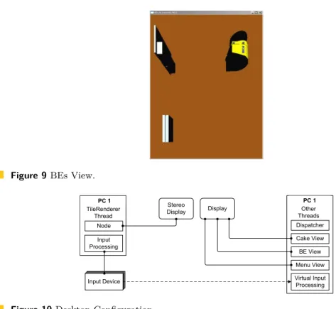
TheBEs View (see Figure 9) is directly related to theModel andMCS Views of Sections 4.1.2 and 4.1.3. In this view, the hardware components related to theBEswithin the selected MCS in theMCS View (Figure 8b) are displayed in more detail. Currently, there are no interaction mechanisms in this view.
Figure 9BEs View. Node TileRenderer Thread Input Processing Input Device Input Device Input Device Input Device PC 1 Dispatcher Cake View BE View Menu View Virtual Input Processing Other Threads PC 1 Stereo Display Display
Figure 10Desktop Configuration.
4.2
Hardware Configurations
The framework presented in this paper is highly flexible in terms of hardware configurations. A text file holds key information for each application such as: the name of the application, the port number associated to it, the PC host name, and a keyword indicating whether it is virtually focussable. Depending on the desired configuration, the developer would need to carry out the following two tasks for each application:
1. Provide the correct host name in the configuration file 2. Supply appropriate orientation and dimension for each view
For the CakES visualization, two different configurations were employed. The first is a two-monitor single-PC solution (see Section 4.2.1), while the second is a nine-monitor five-PC tiled-display solution (see Section 4.2.2).
4.2.1
Desktop
This configuration consisted of a standard monitor with 1920x1200 pixels and a Zalman Trimon passive-stereo monitor with a resolution of 1600x1050. The desktop PC ran on a Windows XP operating system and had the following key components: 2.60 GHz AMD Phenom™ 9950 Quad-Core Processor, 3.25 GB of RAM, and an NVIDIA GeForce GTX 280 graphics card. An additional user defined interaction device, the 3Dconnexion Space Navigator was added. This system was mainly used for development purposes and its physical layout is depicted in Figure 10.
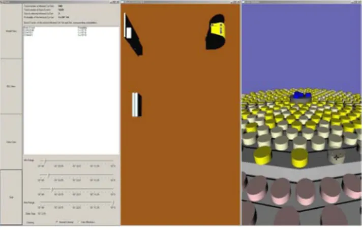
The stereo monitor was used to display the physical parts of the RAVON model as shown in Figure 7. On the other hand, the standard monitor was used to tile theMenu, BEs, and Cake Views next to each other as in Figure 11.
Figure 11Menu, BEs, and MCS Views tiled on a standard PC.
TileRenderer
Display Display Display
Display Display
Display
Display Display Display Node Node Anyscreen Master PC Input Processing Input Device Input Device Input Device Input Device Node Node Anyscreen Slave PC 2 Node Node Anyscreen Slave PC 1 Dispatcher Menu View PC 1 Virtual Input Processing Cake View BE View PC 2 Virtual Input Processing
Figure 12Tiled Wall Configuration.
4.2.2
Tiled Wall
A 3x3 tiled wall with five computers was implemented as depicted in Figure 12. This image is based on the ‘schematic view on a typical 3x3 tiled display’ figure presented by Deller et al. [5], it is modified to incorporate our dispatcher framework. As shown, the tiled wall consists of nine displays controlled by five network-connected PCs. Each computer ran on Windows XP and had the following hardware configuration: Intel® Core™ Dual Core @ 2.4 GHz, 4 GB of RAM, and two GeForce 7950 GX2 graphics cards. Each screen of the tiled wall has a resolution of 2500x1600 pixel, making the total resolution of the wall 7500x4800. Further, there is an upper and a lower separation of the Tiled-Wall:
The upper six displays are managed byTileRenderer - it uses three PCs for this task, where one of them acts as the Master-PC and controls the other two Slave-PCs via the network.
The lower three displays are controlled by the remaining two PCs. One of them runs theDispatcher framework and displays theMenu View on the lower-left screen of the Tiled-Wall. The other is used to visualize theBEs andMCS Views on the remaining two screens.
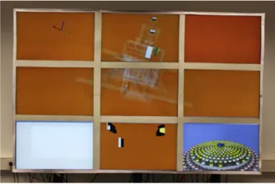
All the above mentioned applications are controlled by the same input devices, which are physically connected to the Master-PC of theTileRenderer. This configuration allows the Master-PC to process input events locally when theModel View application has the virtual focus. On the other hand, it forwards input data via the network to PC1 and PC2
Figure 13Real-Time Tiled-Wall Scenario.
when one of those two applications has thevirtual focus. A screen shot of these applications interacting with one another is illustrated in Figure 13.
5
Conclusion and Future Work
In this paper we have presented a light-weight yet flexible Dispatcher framework that facilitates the simultaneous execution of multiple inter-communicative visualizations built on Open Inventor scene graphs.
TileRenderer was the preferred tiled-display-rendering framework due to its simple yet robust rendering framework. As seen in the case study, it was responsible for rendering theModel View across a large section of the display area. However, the approach was kept flexible enough to let developers employ their own preferred distributed rendering framework. Additional stand-alone visualizations such as the Menu, theBEs View, and theMCS View were rendered separately on three of the tiled-wall displays. All of the above-mentioned visual applications had to be registered with theDispatcher in order to effectively communicate with one another and to appropriately handle the remote input devices via ourVirtual Input implementation.
Through the CakES case study that has been realized using our framework, we tackled our primary goal of efficient tiled-display size and resolution utilization by rendering four different applications and interacting between them. Further, we have been able to develop a system to assist model designers and safety analysts in the context of analyzing embedded system. These applications are highly adaptive, as the developer can easily switch the scene graph database files and still use all our interaction mechanisms. Additionally, there is complete freedom to the number of applications that may be incorporated - it is a simple matter of adding them to the configuration file and providing appropriate display parameters.
The resulting CakES solution worked remarkably well, with the exception of an initial minor glitch - once blending was triggered in theModel View, interaction with the applications through theDispatcherslowed down significantly. After studying this issue further we realized that this was an Open Inventor performance issue due to inadequate volatile memory. Once we increased the RAM from one gigabyte to four, interaction through theDispatcher became virtually real-time.
modules independent of the applications themselves. This would provide us with the ability to easily integrate suitable virtual reality interaction devices and for all the applications to handle interaction via our virtual input mechanism. Currently, only one application is integrated with a distributed rendering framework, we would like to add it to all of them, providing the operator a choice of which application he would like to be tiled. Alternatively, the MCS View may be tiled across a larger area and elements of the BEs View may be explored interactively. Also, projecting a low resolution image onto the bezels of the model view would improve the presentation of the model and the distinction between the different applications (see [5]).
Finally, another possible enhancement is to implement theMessage Handler via interrupts or callbacks instead of polling threads to save CPU cycles. It is planned to conduct a quantitative measure of the framework’s performance, once theDispatcher is improved.
Acknowledgements
I would like to thank the members of both the Computer Graphics and Visualization Group and the Robotics Research Lab in Kaiserslautern, as well as the members of the International Research Training Group (IRTG) for their cooperation. The IRTG is supported by the German Research Foundation (DFG) under contract DFG GK 1131. Furthermore, the authors wish to acknowledge Daniel Steffen from the German Research Center for Artificial Intelligence for his constructive comments and assistance with the TileRenderer framework. This work was supported by the German Federal Ministry of Education and Research (BMBF), under contract number 01 IM 08003, through project ViERforES [23].
References
1 Y. Al-Zokari, T. Khan, D. Schneider, D. Zeckzer, and H. Hagen. CakES: Cake Metaphor
for Analyzing Safety Issues of Embedded Systems. In Hans Hagen, editor, Scientific Vi-sualization: Interactions, Features, Metaphors., volume 2 of Dagstuhl Follow-Ups, pages 1–16, Wadern, Germany, 2011. Schloss Dagstuhl – Leibniz-Zentrum für Informatik. http://dx.doi.org/10.4230/DFU.Vol2.SciViz.2011.1.
2 T. Bedford and P. Gelder.Safety and Reliability : Proceedings of the ESREL 2003 Confer-ence, Maastricht the Netherlands, 15-18 June 2003. Taylor & Francis, 2003.
3 Allen Bierbaum, Christopher Just, Patrick Hartling, Kevin Meinert, Albert Baker, and
Carolina Cruz-Neira. VR Juggler: A Virtual Platform for Virtual Reality Application Development. In VR ’01: Proceedings of the Virtual Reality 2001 Conference (VR’01), page 89, Washington, DC, USA, 2001. IEEE Computer Society.
4 Judith S. Dahmann, Frederick S. Kuhl, and Richard M. Weatherly. Standards for
Simula-tion: As Simple As Possible But Not Simpler The High Level Architecture For Simulation. Simulation, 71(6):378–387, 1998.
5 Matthias Deller, Sebastian Thelen, Daniel Steffen, Peter-Scott Olech, Achim Ebert, Jan
Malburg, and Jörg Meyer. A Highly Scalable Rendering Framework for Arbitrary Display and Display-in-Display Configurations. In Hamid R. Arabnia and Leonidas Deligiannidis, editors,CGVR, pages 164–170. CSREA Press, 2009.
6 Kai-Uwe Doerr and Falko Kuester. CGLX: A Cross-Platform Cluster Graphics Library.
http://vis.ucsd.edu/mediawiki/index.php/Research_Projects:_CGLX; Online; Ac-cessed 23-January-2010.
7 ESSaRel. Background information — ESSaRel, 2002. http://www.essarel.de/ background/background.html; Online; Accessed 30-December-2009.
8 Otmar Hilliges, Lucia Terrenghi, Sebastian Boring, David Kim, Hendrik Richter, and
An-dreas Butz. Designing for collaborative creative problem solving. InC&C ’07: Proceedings of the 6th ACM SIGCHI conference on Creativity & cognition, pages 137–146, New York, NY, USA, 2007. ACM.
9 Greg Humphreys, Mike Houston, Ren Ng, Randall Frank, Sean Ahern, Peter D.
Kirch-ner, and James T. Klosowski. Chromium: a stream-processing framework for interactive rendering on clusters. ACM Trans. Graph., 21(3):693–702, 2002.
10 B. Kaiser, C. Gramlich, and M. Foerster. State/event fault trees - safety analysis model for
software-controlled systems. Reliability engineering & systems safety, 92:1521–1537, 2007.
11 KIST Imaging Media Research. IMRC Wiki: The NAVER framework. http://www.imrc. kist.re.kr/wiki/NAVER_Framework; Online; accessed 23-January-2010.
12 Kongsberg SIM AS. Coin3D: 3D Graphics Developer Kit. http://www.coin3d.org/; Online; Accessed 27-January-2010.
13 N. Limnios. Fault Trees (Control Systems, Robotics & Manufacturing Series). Wiley, John & Sons, 2007.
14 Mechdyne. CAVELib Application programmer interface (API). http://www. mechdyne.com/integratedSolutions/software/products/CAVELib/CAVELib.htm; On-line; Accessed 23-January-2010.
15 Tao Ni, Greg S. Schmidt, Oliver G. Staadt, Mark A. Livingston, Robert Ball, and Richard
May. A Survey of Large High-Resolution Display Technologies, Techniques, and Applica-tions. In VR ’06: Proceedings of the IEEE conference on Virtual Reality, pages 223–236, Washington, DC, USA, 2006. IEEE Computer Society.
16 Bruno Raffin and Luciano Soares. PC Clusters for Virtual Reality. InVR ’06: Proceedings of the IEEE conference on Virtual Reality, pages 215–222, Washington, DC, USA, 2006. IEEE Computer Society.
17 RAVON. AG Robotersysteme: Ravon, 2009. http://agrosy.informatik.uni-kl.de/ en/robots/ravon/; Online; Accessed 30-December-2009.
18 RealityPrime. Scenegraphs: Past, present, and future. http://www.realityprime.com/ articles/scenegraphs-past-present-and-future; Online; Accessed 29-January-2010.
19 Benjamin Schaeffer and Camille Goudeseune. Syzygy: Native PC Cluster VR. Virtual Reality Conference, IEEE, 0:15, 2003.
20 SDL: Simple DirectMedia Layer. A cross-platform multimedia library.http://www.libsdl. org/cgi/docwiki.cgi/; Online; Accessed 15-December-2009.
21 Luciano P. Soares and Marcelo K. Zuffo. JINX: an X3D browser for VR immersive
simu-lation based on clusters of commodity computers. InWeb3D ’04: Proceedings of the ninth international conference on 3D Web technology, pages 79–86, New York, NY, USA, 2004. ACM.
22 Munjae Song, Seongwon Park, and Yongbin Kang. A Survey on Projector-Based PC Cluster
Distributed Large Screen Displays and Shader Technologies. In Hamid R. Arabnia, editor, CGVR, pages 153–159. CSREA Press, 2007.
23 ViERforES. Virtuelle und Erweiterte Realität für höchste Sicherheit und Zuverlässigkeit
von Eingebetteten Systemen, 2009. http://www.vierfores.de/; Online; Accessed 02-February-2010.
24 S. Vinoski. CORBA: integrating diverse applications within distributed heterogeneous