Direct Numerical Simulation of Receptivity to
Roughness in a Swept-Wing Boundary Layer at High
Reynolds Numbers
Gary Nicholson
∗, Chao Zhang
†, Lian Duan
‡ Missouri University of Science and Technology, Rolla, MO 65409Mujeeb Malik
§, Fei Li
¶NASA Langley Research Center, Hampton, VA 23681
Ali Uzun
kNational Institute of Aerospace, Hampton, VA 23666
Direct numerical simulations (DNS) are performed to examine the receptivity to rough-ness in a spatially developing three-dimensional boundary layer over an infinite-swept natural-laminar-flow wing at a freestream Mach number of 0.75 and a chord Reynolds number of approximately 25million based on the long, swept chord. Stationary crossflow disturbances are excited by applying either critically spaced discrete cylinders of micron size or naturally occurring distributed roughness in the leading-edge region. The DNS data show that the spanwise spectral content of the excited crossflow disturbances is highly de-pendent upon the shape of roughness elements, and the initial growth of the crossflow structures is a nonlinear function of the element height. The linear growth rate of the excited crossflow disturbances predicted by DNS shows good agreement with linear parab-olized stability equations. The receptivity study lays the foundation for investigating the stabilization of the naturally most unstable steady crossflow mode by using spanwise peri-odic DREs.
Nomenclature
a speed of sound, m/s
c unswept chord measured in direction perpendicular to leading edge, m
cs long, swept chord measured in direction parallel to the incoming freestream velocity,cs=c/cos(Λ), m
dr diameter of cylindrical roughness elements, m
hr height of cylindrical roughness elements, m
Cp pressure coefficient,Cp= (p−p∞)/(0.5ρ∞Q2∞), dimensionless
M∞ freestream Mach number,M∞=Q∞/a∞, dimensionless
Rec Reynolds number based on unswept chordc,Rec≡ρ∞Q∞c/µ∞, dimensionless
Recs Reynolds number based on swept chordcs,Recs ≡ρ∞Q∞cs/µ∞, dimensionless Q∞ free flight velocity, m/s
T temperature, K
u chordwise velocity, m/s
v spanwise velocity, m/s
∗Graduate Research Assistant, Student member, AIAA †Graduate Research Assistant, Student member, AIAA ‡Assistant Professor. Senior member, AIAA
§Senior Aerodynamicist, Computational AeroSciences Branch, M.S. 128. Fellow, AIAA ¶Aerospace Technologist, Computational AeroSciences Branch, M.S. 128
kSenior Research Scientist. Senior member, AIAA
w normal-to-the-chord velocity, m/s
x Cartesian coordinate in the chordwise direction perpendicular to the leading edge of the swept wing
y Cartesian coordinate in the spanwise direction parallel to the leading edge of the swept wing
z Cartesian coordinate normal to the chord
i curvilinear coordinate along the vortex axis in the nonorthogonal system
j curvilinear coordinate parallel to the leading edge in the nonorthogonal system
k curvilinear coordinate defining the wall-normal direction in the nonorthogonal system
Lr spacing of the spanwise array of roughness elements, m
Ly spanwise domain size of DNS, m
As modal amplitude of the chordwise velocity perturbationAs= max
k |uˆs|, m/s
N logarithmic-amplification ratio,N = log(As(i)/As(i0)), dimensionless Λ wing sweep angle, degree
β0 fundamental disturbance spanwise wave number, m−1 Subscripts
r quantities related to roughness
rms root mean square w wall variables ∞ freestream variables
Superscripts
+ inner wall units
(·) unperturbed baseflow variables
(·)0 perturbation from the baseflow due to roughness (·)∗ complex conjugate
ˆ
(·) spanwise Fourier transformed variables
I.
Introduction
Skin-friction drag accounts for approximately one-half of the total drag for business jets and long-haul transport aircraft. Transition delay via laminar flow technology is an important component of drag reduction technologies. Although system studies have shown that 9–10% fuel savings can be achieved by delaying boundary-layer transition over major aerodynamic surfaces, the projected benefits can be significantly offset by uncertainties in transition prediction. To enable usable and robust designs for Natural Laminar Flow (NLF) and Hybrid Laminar Flow Control (HLFC), linking transition prediction to high-fidelity aircraft design tools is critical. One important technical gap that prevents accurate transition prediction in swept-wing boundary layers is the transition due to crossflow instability, which is extremely sensitive to surface roughness, especially near the wing leading edge.1, 2
In three-dimensional swept-wing boundary layers, crossflow instability often manifests itself in the form of stationary corotating streamwise vortices that originate at minute roughness sites. Amplitude of the induced stationary disturbances is directly related to the leading-edge surface finish. It has been found that the growth of these crossflow disturbances can be delayed by placing discrete roughness elements (DREs) of subcritical wavelengths near the wing leading edge.3, 4 The effectiveness of the DRE concept has been demonstrated in a bulk of the existing experimental and computational studies, and these studies were carried out for low-Mach-number (M∞<0.3) configurations with modest wing-chord Reynolds numbers of
up to approximately Recs = 8×10
6,1, 2, 5–10 and with pressure distributions that may not be optimal for wing designs for subsonic transport aircraft flying at Mach numbers between 0.75 and 0.90.
To further assess the potential capability of the DRE concept to control swept-wing transition at transonic Mach numbers and substantially higher chord Reynolds numbers than previous applications, a high-Reynolds-number flight experiment, referred to as the Subsonic Aircraft Roughness Glove Experiment (SARGE), was recently initiated to design high-Reynolds-number NLF wing configurations with a maximum possible chord Reynolds number approachingRecs = 30×10
6.11 For such configurations, Malik et al.12 and Li et al.13 conducted a computational assessment of the DRE concept using nonlinear parabolized stability equations (PSE) and secondary-instability analysis, with the particular conditions used for the assessment consisting of a freestream Mach number of 0.75 and chord Reynolds numbers of 17×106, 24×106, and 30×106. The computations demonstrated that DREs can suppress dominant boundary-layer disturbances
at the chosen Reynolds numbers. However, in their calculations the receptivity phase was not incorporated. Instead, a linear eigenmode was used to initialize the calculation while the impact of the actual surface rough-ness to initiate natural crossflow disturbances, as well as the control mode, was not simulated. Given that it is not known how far downstream of the DREs a crossflow eigenmode shape develops and what the relation of its amplitude to the height and shape of the roughness is, a further study of receptivity to roughness (i.e., the relation between the size and/or distribution of roughness and induced stationary disturbance in the boundary-layer) is needed for given DRE height, shape, and location in order to draw definitive conclusions on whether DREs can delay crossflow-induced transition.
Direct numerical simulation (DNS) is a valuable tool that can be combined with stability analysis to estimate the range of amplitudes of the stationary-crossflow instabilities excited by surface roughness. DNS can be used to elucidate features of roughness-induced flow fields8, 14and validate reduced-order receptivity models such as those based on PSE15 and linearized Navier-Stokes equations.16, 17 For instance, Tempel-mann et al.15 studied receptivity to DREs using a combination of DNS and PSE with the flow conditions corresponding to wind-tunnel experiments by Saric and coworkers at Arizona State University (ASU).18 In their study, DNS solutions were used to provide insight into different roughness parameter effects and to validate a receptivity model based on direct and adjoint PSEs. Rizzetta et al.8 studied the excitation of crossflow instabilities with critically spaced DREs placed near a swept-wing leading edge, with flow config-uration corresponding to the low-speed swept-wing flight test (SWIFT) by the Texas A&M University.1, 2 They found that the initial growth of the velocity amplitude displayed a nonlinear dependence on elemental height, indicating the necessity for performing a DNS for each roughness configuration in order to obtain meaningful perturbation quantities that may then be used to carry out stability calculations. The DNS were also fed into the downstream region as initial conditions for nonlinear PSE (NPSE) computations and the combined NPSE and DNS approach were found to produce nearly identical initial growth rates as the full DNS. As far as transition control with DREs is concerned, Wasserman and Kloker7conducted a DNS study of control of crossflow vortices in a three-dimensional (3-D) low-speed flat-plate boundary layer. Hosseini et al.10 further conducted DNS to study the stabilization of a swept-wing boundary layer by DREs with flow conditions representative of the ASU experiments. Both studies concluded that DREs stabilizes the primary crossflow modes and attenuates the growth of secondary instabilities. So far, none of the previous DNS of receptivity to DREs were carried out with Mach number, Reynolds number, and pressure distributions that are relevant to subsonic transport aircraft.
To complement the stability analysis by Malik et al.12 and Li et al.13 as well as to provide computational assessment of the DRE technology for potential application to transport aircraft, the current paper studies the receptivity to roughness using DNS of compressible Navier-Stokes equations for a spatially developing transonic 3-D boundary layer over a realistic NLF wing configuration at Reynolds numbers relevant to transport aircraft. DNS results are analyzed to determine the initial amplitude and mode shapes of induced stationary crossflow modes as well as to shed light on the relation of the modal amplitudes to the size and distribution of roughness.
The paper is structured as follows. The flow conditions and numerical methods are outlined in Sec-tion II. SecSec-tion III presents DNS results of the baseflow and the growth of roughness-induced disturbances. Section IV gives a summary of the current study.
II.
Flow Conditions and Numerical Methodology
The work in this paper considers the boundary layer over a swept NLF wing (G-IIB, TAMU-0706 wing glove) designed by Tufts et al.19 at Texas A & M University. The design of TAMU-0706 wing glove has improved upon that of Belisle et al.11 with a truly uniform flow in the spanwise direction and substantially improved stability characteristics. The target design conditions consist of M∞ = 0.75 at an altitude of
H = 40 kft, an angle of attack (AoA) of 3.7 degrees, a chord Reynolds number, Recs, of 24.77 million,
and a leading-edge sweep angle, Λ, of 30◦. The free flight conditions for the work described in this paper are summarized in Table 1. In this paper, we focus on an infinite-swept TAMU-0706 wing at an AoA of 1.9375 degrees. For the selected angle of attack, the surface pressure coefficientCp near the leading edge
of the infinite-swept wing matches as closely as possible that of the three-dimensional (3-D) finite-swept counterpart at the design AoA of 3.7 degrees (See Figure 5a in Section III).
For the selected configuration, two types of DNS are carried out. A DNS without roughness, referred to as DNS-I, is first computed to simulate the steady baseflow that serves to provide boundary conditions
Table 1. Free flight conditions for the DNS.
M∞ Q∞(m/s) ρ∞ (kg/m3) T∞ (K) c (m) Rec(×106) Recs(×10
6) 0.75 221.28 0.302 216.65 3.83 21.45 24.77
for a second DNS that includes roughness, referred to as DNS-II. To select a suitable domain for DNS-I, a precursor Reynolds-averaged Navier-Stokes (RANS) simulation of the flow for the entire wing is carried out and the flow field is explored. In the RANS, the Spalart-Allmaras turbulence model is used; and the flow is assumed to be homogeneous in the spanwise direction. The flow is set to be laminar over the first 61% of the wing on both the upper and lower surfaces and the turbulence model is only switched on outside of the laminar region. In DNS-II, surface roughness is incorporated to excite crossflow disturbances. The roughness elements implemented in the DNS include a spanwise periodic row of discrete circular cylinders of various height and diameters that is formed by displacing the corresponding mesh points at the wall (Section B) and naturally occurring distributed roughness that is modeled by an appropriate roughness model combined with inhomogeneous boundary conditions at the undisturbed wall (Section C).
The wing and the adopted coordinate systems are shown in Figure 1. A nonorthogonal coordinate system is used for the current DNS. In this coordinate system, the body-fitted curvilinear computational coordinateiis approximately aligned with the crossflow vortex axis rather than along the chordwise direction (xdirection). By doing so, the number of grid points, which is required in the streamwise direction due to the relatively slow evolution of crossflow modes along this direction, can be substantially reduced. The spanwise computational coordinatej is along theydirection, which is parallel to the leading edge of the wing and at an acute angle to thei-coordinate. Similar nonorthogonal systems have been chosen in spatially developing secondary instability analyses20 and DNS21, 22 for crossflow-dominated swept-wing boundary layers. Both DNS-I and DNS-II simulate the physical boundary layer over the TAMU wing extending approximately from x/c = 0.006 on the wing lower surface or windward side to x/c = 0.7 on the wing upper surface or leeward side. Only the flow field on the leeward side is of interest, while part of the windward side is retained to account for the asymmetry of the configuration. Negligible differences have been observed when the domain is further enlarged on the wing lower surface. The domain size in the spanwise direction is set to be equal to the spacingLrof the spanwise array of roughness elements. Sponge regions are inserted in both
types of DNS in order to minimize acoustic reflections at the lower and upper outlets and at the freestream boundary (Figure 2). Within these sponge regions, the flow is forced towards the RANS solution for the entire TAMU wing. On the wall, no-slip conditions are applied for the three velocity components and the temperature is extracted from the RANS solution in which an adiabatic condition is used; and the extracted wall temperature is prescribed as Dirichlet conditions in the DNS.
To simulate the boundary layer flow over the domain, the compressible Navier-Stokes equations are solved in generalized curvilinear coordinates. The working fluid is assumed to be an ideal gas with a linear (i.e., Newtonian) stress-strain relation. The Fourier law is used to compute the heat flux terms. A 7th-order weighted essentially nonoscillatory (WENO) scheme23is used to compute the convective flux terms. Given the subsonic nature of the flow without shock waves, the optimal 9-point WENO stencil is used in the simulations with WENO adaptation turned off to reduce numerical dissipation. For the viscous flux terms, a 4th-order central difference scheme is used. The 3rd-order low-storage Runge-Kutta scheme by Williamson24 is used for time integration.
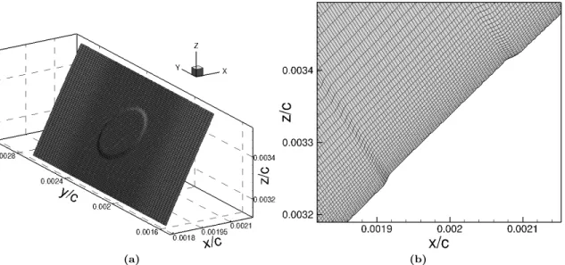
The total number of grid points is 4949, 320, and 295 in the streamwise (i), spanwise (j), and wall-normal (k) directions, respectively. The grid is clustered near the wall and close to the roughness element (Figure 3). The computational grid resolution is comparable to those reported in the literature in the context of previous simulations of turbulent wall-bounded flows using comparable numerical algorithms.22 Moreover, a grid convergence study shows that negligible differences are observed for the reported quantities by further refining the meshes in each direction, as illustrated in Figure 4.
Figure 1. Swept TAMU-0706 wing, with sweep angle Λ = 30◦ and the total incoming velocity
Q∞. The wing is at an angle-of-attack of1.9375◦. Here,(i, j, k)and(x, y, z)represent locally fitting
curvilinear and Cartesian coordinate systems, respectively. The colored contours denote the chordwise velocity (u) from the RANS. The blue lines represent the crossflow vortex axis.
(a) (b)
Figure 3. (a) Meshed cylindrical roughness element generated by displacing the corresponding mesh points at the wall; (b) A close-up of the mesh in a x-z plane (y= 0.5Lr) near the roughness
element.
Figure 4. Grid convergence study for chordwise evolution of disturbance amplitudes As of the
fundamental modeβ0 = 2π/Lr and the first superharmonic 2β0 for Case Cyl D1 H10 L8p5. As is
III.
Results
In this Section, the validity of the DNS-computed baseflow of the infinite-swept NLF wing is first verified; next, DNS results of receptivity to localized and natural surface roughness on the wing are introduced; finally, the stabilization of crossflow instabilities with subcritical DREs is simulated by the DNS.
A. Baseflow Results
To check the validity of the baseflow computed by the DNS, Figures 5a and 5b show comparisons in surface pressure coefficient and the density contours, respectively, between the full-wing RANS and DNS-I that consists of a partial wing. Excellent comparison between the RANS and the DNS is achieved for both quantities. In particular, Figure 5a shows that the RANS and DNS results for the infinite-swept wing closely match that of the 3D finite-swept wing with an AoA of 3.7 degrees forx/c <0.45. Small differences inCp
exist over the leading edge between the 3D and the infinite-swept wings. Such differences might be due to the slight geometric smoothing applied to the leading-edge region or due to the infinite-swept-wing assumption.
(a) (b)
Figure 5. (a) Surface pressure coefficientCp obtained from the DNS and RANS for the
infinite-swept wing (without roughness) in comparison with the results in Tufts et al.19 The inset provides a zoomed-in view of all Cp curves over the leading edge. (b) Density contours of the baseflow
obtained from the RANS calculation of the entire wing and the current DNS.
B. Receptivity to Discrete Surface Roughness
Next, DNS results of receptivity to a spanwise array of micron-sized circular cylinders are presented. In each DNS, stationary crossflow modes are excited by inserting a single roughness element in the form of a shallow cylindrical disk near the leading edge, and spanwise periodic boundary conditions are prescribed to mimic a row of spanwise periodic roughness. The use of a single roughness in the DNS domain with spanwise periodic boundary conditions has been shown to be adequate for modeling a spanwise cyclic roughness array.15 The roughness is inserted into the computational grid by deforming the baseline grid to accommodate the change in surface geometry as shown in Figure 3. The edges of cylindrical roughness elements are slightly rounded to avoid singularities in computations of grid metrics. Table 2 lists roughness parameters and provides an overview of the cases. The spanwise roughness spacing Lr is chosen to be 8.5 mm, corresponding to the
wavelength of the naturally most unstable stationary crossflow mode. The roughness elements are placed near the leading edge at 0.2% of the chord (x/c = 0.002). Different roughness heights and diameters are used to provide insight into the sensitivity of receptivity to roughness parameters.
Table 2. Overview of DNS cases for studying receptivity to localized surface roughness together with the respective roughness parameters.
Case Location Diameter Height Spacing
xr/c dr(mm) hr(µm) Lr(mm)
Cyl D1 H10 L8p5 0.002 1 10 8.5
Cyl D2 H10 L8p5 0.002 2 10 8.5
Cyl D1 H20 L8p5 0.002 1 20 8.5
Figure 6 depicts various planes of the total chordwise velocity ((u+u0)/Q∞) extracted from the flow
field downstream of the cylindrical roughness element (dr =1 mm andhr = 10 µm). Spanwise variations
of the flow field become apparent for x/c > 0.42, suggesting that the excited disturbance has reached an amplitude of the order of the baseflow at this location. The overturning flow structures forx/c >0.42 are characteristic of crossflow disturbances and conform to those observed by previous studies.5, 6, 18
Figure 6. Planes of the total velocity field(u+u0)/Q∞as predicted by DNS for roughness element
with dr =1 mm and hr = 10 µm (Case Cyl D1 H10 L8p5). The four slices of pseudocolors are
located atx/c= 0.35, 0.42, 0.48, 0.53. The flow is duplicated periodically in the spanwise direction.
Figure 7 plots the r.m.s. of the chordwise velocity disturbances u0
rms/Q∞ as a function of x/c for the
three roughness cases. As expected, the disturbance magnitude increases as the roughness size becomes larger. Similar increases inu0rms/Q∞are shown by either doubling the roughness height or by doubling the
diameter. For the baseline roughness case withdr=1 mm andhr= 10µm,u0rms/Q∞becomes approximately
7% atx/c= 0.42, which suggests a nonlinear interaction and is consistent with the apparent appearance of overturning-wave structures shown in Figure 6.
To characterize the initial spanwise content of the roughness-induced perturbations, Figure 8 plots the initial spanwise wavenumber spectra of the maximum chordwise velocity perturbation at multiple streamwise locationsx/c. The modal amplitudeAs is extracted from the DNS data by means of Fourier transform in
the spanwise direction, with the first (or fundamental) mode corresponding to the fundamental interelement spacingLr= 8.5 mm. Immediately downstream of the roughness atx/c= 0.004, there exists a wide range
of spanwise modes, and the initial spectral content is highly sensitive to the diameter and height of the roughness elements. Most of the small-wavelength disturbances decay over relatively short disturbances and
Figure 7. Chordwise evolution of crossflow disturbances for cylindrical roughness with differ-ent parameters (Cases Cyl D1 H10 L8p5, Cyl D2 H10 L8p5, Cyl D1 H20 L8p5) as predicted by DNS.
nonnegligible contributions to the spectral content is observed only for the first five modes afterx/c= 0.05. Shown in Figure 9 are the normalized spanwise wavenumber spectra, where the amplitude of each mode has been normalized by the corresponding amplitude for the baseline case with dr = 1 mm, hr = 10
µm (Case Cyl D1 H10 L8p5). Thus, all the normalized amplitudes are identically equal to 1.0 for Case Cyl D1 H10 L8p5, and the normalized values would be 2.0 for Cases Cyl D1 H20 L8p5 and Cyl D2 H10 L8p5 if the amplitudes varied linearly with element height and diameter. Figure 9 shows that the initial amplitude of the crossflow disturbances is a nonlinear function of the elemental height and diameter, although a roughly linear dependence has been found for the r.m.s of chordwise velocity perturbation in Figure 7. The nonlinear dependence of modal amplitude on roughness parameters is consistent with the finding of Rizzetta et al. in their DNS study of receptivity to DREs over the SWIFT configuration.8 Figure 10 further shows the downstream evolution of modal amplitudes, As, of the fundamental mode β0 = 2π/Lr and the
first four superharmonics for all cylindrical roughness elements. The fundamental 8.5-mm mode (β0) grows continuously through the domain, as expected, and becomes dominant afterx/c = 0.25. The other modes also grow initially, but modes decay further downstream before nonlinear interaction kicks in atx/c≈0.35. A similar trend has also been reported by Tempelmann et al.15 in their study of receptivity to DREs for the SWIFT configuration. The significant initial growth of the 4.25-mm mode (2β0) and the 2.833-mm mode (3β0) may suggest that either mode could be used as a “control mode” for controlling the most unstable 8.5-mm mode.
Figure 11 shows a comparison in N-factors of the fundamental modeβ0and the first superharmonic 2β0 between the DNS and the linear PSE. Good agreement is achieved between the results of DNS and PSE for 0.1 < x/c < 0.28. The discrepancies between DNS and linear PSE results for x/c >0.28 may be due to nonlinear interaction or additional nonmodal effects in the DNS that are not included in the linear PSE calculation.
C. Receptivity to Distributed Natural Surface Roughness
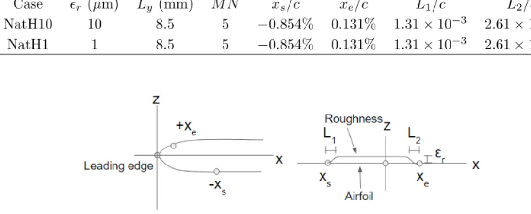
Further, the emergence of unstable crossflow modes due to the presence of natural surface roughness in the leading edge region is computed by DNS. We simulate the effect of natural surface roughness following a procedure proposed by Hosseini et al.,10 in which roughness is modeled by covering the leading-edge region of the infinite-swept wing with a spanwise periodic roughness strip of the form
hr(x, y) =rHβ(x) M N X n=1 sin(nβ0y+ϕn), with β0= 2π/Ly, Hβ(x) = S x−x s L1 −S x−x e L2 + 1 . (1)
(a)x/c= 0.004 (b)x/c= 0.05 (c)x/c= 0.1
Figure 8. Initial spanwise wavenumber spectra of the maximum chordwise velocity perturbation for all roughness elements: (a)x/c= 0.004; (b)x/c= 0.05; (c)x/c= 0.1.
(a)x/c= 0.004 (b)x/c= 0.05 (c)x/c= 0.1
Figure 9. Nondimensional initial spanwise wavenumber spectra of the maximum chordwise veloc-ity perturbation for all roughness elements, with the amplitude of each mode normalized by the corresponding amplitude of the Case Cyl D1 H1 L8p5 (dr = 1mm, hr = 10 µm): (a) x/c= 0.004;
(b)x/c= 0.05; (c) x/c= 0.1.
(a) (b) (c)
Figure 10. Disturbance amplitudes As of the fundamental modeβ0 (8.5-mm mode) and the first
four superhamonics (2β0, 3β0, 4β0, 5β0) as predicted by DNS for cylindrical roughness elements
with a spanwise spacing of Lr = 8.5 mm. (a) dr= 1 mm, hr = 10µm; (b)dr = 2 mm, hr= 10 µm;
Figure 11. Logarithmic-amplification ratios N of the fundamental mode β0 and the first
super-harmonic2β0 as predicted by DNS and linear PSE for roughness cases with Lr= 8.5mm.
Herehrdenotes the wall-normal displacement whose magnitude can be adjusted with the value ofr;β0and
Lyis the spanwise wavenumber and DNS domain size, respectively;xsandxedenote the starting and ending
chordwise locations of the roughness strip, respectively;L1andL2 are the lengths of the smoothing zone at the start and end of the roughness, respectively; S is a smooth step function defined in Schrader et al.;25 and ϕn is the modal phase chosen randomly. Because of the spanwise periodic boundary conditions, only
disturbances with a wavenumber ofnβ0 (n= 1, 2, ...) can be accounted for in the DNS. Figure 12 provides a schematic of the model parameters. The roughness model, referred to in this paper as “natural” surface roughness, is implemented as inhomogeneous boundary conditions by projecting the no-slip conditions on the surface of the roughness to the undisturbed wall using Taylor-series expansions as26
u|w=−hr ∂u ∂n w v|w=−hr ∂v ∂n w w|w=−hr ∂w ∂n w T|w=T|w−hr ∂T ∂n w . (2)
Table 3 lists the values of the model parameters for the DNS of receptivity to natural surface roughness. The roughness parameters are determined based on the lessons learned from the study of receptivity to cylindrical roughness elements as discussed in Section B. In particular, the mode numberM N is chosen to be 5 as the DNS of receptivity to cylindrical roughness elements show that only the 8.5-mm mode (β0) and the first four superhamonics (2β0, 3β0, 4β0, 5β0) grow significantly (Figure 10).
Figures 13a and 13b show the chordwise evolution of disturbance amplitudes As for the DNS cases
with natural surface roughness NatH10 and NatH1, respectively, while Figure 14 shows the logarithmic-amplification ratiosN. Receptivity of the laminar swept-wing boundary layer is sensitive to the distribution of roughness, with the initial amplitude of the crossflow disturbances excited by natural roughness significant larger than that induced by cylindrical roughness of the same height. The 8.5-mm mode (β0) and the first four superhamonics excited by natural surface roughness show a chordwise growth similar to those forced by cylindrical roughness before they become saturated due to nonlinear effects; the 8.5-mm mode becomes dominant over all the smaller wavelength modes afterx/c= 0.2 and remain unstable over longer streamwise disturbances, while all the smaller wavelength modes grow first (i.e., at small distance from the wing leading edge) but decay farther downstream. Among all the superhamonics, the 4.25-mm mode (2β0) and the
2.833-mm mode (3β0) experience strong initial growth and their initial amplitudes are maintained over a relatively large streamwise distance up tox/c≈0.2.
Table 3. Summary of roughness parameters for DNS study of receptivity to distributed natural surface roughness.
Case r(µm) Ly (mm) M N xs/c xe/c L1/c L2/c NatH10 10 8.5 5 −0.854% 0.131% 1.31×10⁻³ 2.61×10⁻⁴
NatH1 1 8.5 5 −0.854% 0.131% 1.31×10⁻³ 2.61×10⁻⁴
Figure 12. Schematic of the model parameters for natural roughness used in the DNS.
(a) (b)
Figure 13. Disturbance amplitudesAs as predicted by DNS for distributed natural surface
rough-ness (a) Case NatH10 (b) Case NatH1.
IV.
Summary
Direct numerical simulations (DNS) are performed to examine the receptivity to roughness in a spatially developing subsonic swept-wing boundary layer over an infinite-swept natural-laminar-flow wing configura-tion (GII-B, TAMU-0706) at high Reynolds numbers relevant to transport aircraft. The surface roughness is implemented in the DNS either as discrete meshed cylinders combined with cyclic boundary conditions, which mimics a spanwise periodic row of roughness elements, or as an appropriate simplified roughness model combined with inhomogeneous boundary conditions at the undisturbed wall, which mimics naturally occur-ring distributed roughness. Roughness parameters are varied in the DNS to explore the relation between the size and distribution of roughness and the induced crossflow disturbances in the boundary layer. The main observations and conclusions summarized as follows:
Figure 14. Logarithmic-amplification ratiosN as predicted by DNS for distributed natural surface roughness.
(i) Both cylindrical and natural roughness elements can excite a wide spectrum of spanwise modes. (ii) The initial spanwise spectral content is highly dependent upon the shape of roughness elements. (iii) The initial growth of the crossflow structures is a nonlinear function of the element height.
(iv) The linear growth of the excited unstable crossflow disturbances predicted by DNS shows good agree-ment with linear PSE.
The receptivity study lays the foundation for investigating the stabilization of the naturally most unstable steady crossflow mode by using spanwise periodic DREs. Currently DNS that implement both natural roughness and control cylinders are being conducted; the DNS simulate a typical experiment scenario in which multiple steady crossflow modes including the most unstable mode (i.e., the “target” mode) emerge because of the presence of naturally distributed surface roughness in the leading edge region and spanwise periodic control cylinders of subcritical wavelength are used to force small-wavelength disturbances (i.e., the control mode) for damping the target mode. The DNS results will be used to show the effectiveness of DREs in attenuating the naturally most unstable steady crossflow mode at high Reynolds numbers relevant to transport aircraft.
Acknowledgments
This work was originally sponsored under the NASA Environmentally Responsible Aviation Project.
References
1Carpenter, A. L., Saric, W. S., Reed, H. L., and Saric, W. S., “Laminar Flow Control on a Swept Wing with Distributed
Roughness,” AIAA Paper 2008-7335, 2008.
2Saric, W. S., Carpenter, A. L., and Reed, H. L., “Passive Control of Transition in Three-Dimensional Boundary Layers,
with Emphasis on Discrete Roughness Element,”Phil. Trans. R. Soc. A, Vol. 369, No. 1940, 2011, pp. 1352–1364.
3Saric, W. S., Carrillo, R. B., and Reibert, M. S., “Nonlinear Stability and Transition in 3-D Boundary Layers,”Meccanica,
Vol. 33, 1998, pp. 469–487.
4Saric, W. S., Carrillo, R. B., and Reibert, M. S., “Leading-edge Roughness as a Transition Control Mechanism,” AIAA
Paper 1998-0781, 1998.
5Malik, M. R., Li, F., Choudhari, M. M., and Chang, C. L., “Secondary Instability of Crossflow Vortices and Swept-Wing
Boundary-Layer Transition,”Journal of Fluid Mechanics, Vol. 399, 1999, pp. 85–115.
6Haynes, T. S. and Reed, H. L., “Simulation of Swept-Wing Vortices using Nonlinear Parabolized Stability Equations,”
7Wassermann, P. and Kloker, M., “Mechanisms and Passive Control of Crossflow-Vortex-Induced Transition in a
Three-Dimensional Boundary Layer,”Journal of Fluid Mechanics, Vol. 456, 2002, pp. 49–84.
8Rizzetta, D. P., Visbal, M. R., Reed, H. L., and Saric, W. S., “Direct Numerical Simulation of Discrete Roughness on a
Swept-Wing Leading Edge,”AIAA Journal, Vol. 48, No. 11, 2010, pp. 2660–2673.
9Li, F., Choudhari, M. M., Chang, C.-L., Streett, C., and Carpenter, M., “Computational Study of Laminar Flow Control
on a Subsonic Swept Wing Using Discrete Roughness Elements,”AIAA Journal, Vol. 49, No. 3, 2011, pp. 520–529.
10Hosseini, S. M., Tempelmann, D., Hanifi, A., and Henningson, D. S., “Stabilization of a Swept-Wing Boundary Layer by
Distributed Roughness Elements,”Journal of Fluid Mechanics, Vol. 718, 2013, pp. R1–R11.
11Belisle, M. J., Roberts, M. W., Tufts, M. W., Tucker, A. A., Williams, T., Saric, W. S., and Reed, H. L., “Design of the
Subsonic Aircraft Roughness Glove Experiment (SARGE),” AIAA Paper 2011-3524, 2011.
12Malik, M., Liao, W., Li, F., and Choudhari, M., “Discrete-Roughness-Element-Enhanced Swept-Wing Natural Laminar
Flow at High Reynolds Numbers,”AIAA Journal, Vol. 53, No. 8, 2015, pp. 2321–2334.
13Li, F., Choudhari, M. M., Carpenter, M., Malik, M., Chang, C.-L., and Streett, C., “Control of Crossflow Transition at
High Reynolds Numbers Using Discrete Roughness Elements,”AIAA Journal, Vol. 54, No. 1, 2016, pp. 39–52.
14Piot, E., Content, C., and Casalis, G., “Receptivity of Crossflow Instabilities to a Periodic Roughness Array on a Swept
Cylinder: Investigation of the Roughness Size Influence,” AIAA Paper 2008-0502, 2008.
15Tempelmann, D., Schrader, L. U., Hanifi, A., Brandt, L., and Henningson, D. S., “Swept Wing Boundary-Layer
Recep-tivity to Localized Surface Roughness,”Journal of Fluid Mechanics, Vol. 711, 2012, pp. 516–544.
16Collis, S. S. and Lele, S. K., “Receptivity to Surface Roughness Near a Swept Leading Edge,”Journal of Fluid Mechanics,
Vol. 380, 1999, pp. 141–168.
17Thomas, C., Mughal, S., and Ashworth, R., “On Predicting Receptivity to Surface Roughness in a Compressible Infinite
Swept Wing Boundary Layer,”Physics of Fluids, Vol. 29, No. 3, 2017, pp. 034102.
18Reibert, M. S.,Nonlinear Stability, Saturation, and Transition in Crossflow-Dominated Boundary Layers, Ph.D. thesis,
Arizona State University, 1996.
19Tufts, M. W., Reed, H. L., and Saric, W. S., “Design of an Infinite-Swept-Wing Glove for In-Flight
Discrete-Roughness-Element Experiment,”Journal of Aircraft, Vol. 51, No. 5, 2014, pp. 1618–1631.
20Li, F. and Choudhari, M. M., “Spatially Developing Secondary Instabilities and Attachment Line Instability in Supersonic
Boundary Layers,” AIAA Paper 2008-590, 2008.
21Jiang, L., Choudhari, M. M., Chang, C. L., and Liu, C., “Direct Numerical Simulations of Crossflow Disturbances in
Supersonic Boundary Layers,” AIAA Paper 2004-589, 2004.
22Duan, L., Choudhari, M. M., and Li, F., “Direct Numerical Simulation of Transition in a Swept Boundary Layer,” AIAA
Paper 2013-2617, 2013.
23Jiang, G. S. and Shu, C. W., “Efficient Implementation of Weighted ENO Schemes,”Journal of Computational Physics,
Vol. 126, No. 1, 1996, pp. 202–228.
24Williamson, J., “Low-Storage Runge-Kutta Schemes,”Journal of Computational Physics, Vol. 35, No. 1, 1980, pp. 48–56. 25Schrader, L. U., Brandt, L., and Henningson, D. S., “Receptivity Mechanisms in Three-Dimensional Boundary Layer
Flows,”Journal of Fluid Mechanics, Vol. 618, 2009, pp. 209–241.
26Choudhari, M. and Streett, C. L., “A Finite Reynolds-number Approach for the Prediction of Boundary-Layer Receptivity