Engineering Trustworthy Self-Adaptive Software
with Dynamic Assurance Cases
Radu Calinescu, Danny Weyns, Simos Gerasimou, M. Usman Iftikhar, Ibrahim Habli, and Tim Kelly
Abstract—Building on concepts drawn from control theory,self-adaptive softwarehandles environmental and internal uncertainties by dynamically adjusting its architecture and parameters in response to events such as workload changes and component failures. Self-adaptive software is increasingly expected to meet strict functional and non-functional requirements in applications from areas as diverse as manufacturing, healthcare and finance. To address this need, we introduce a methodology for the systematic ENgineering of TRUstworthy Self-adaptive sofTware (ENTRUST). ENTRUST uses a combination of (1) design-time and runtime modelling and verification, and (2) industry-adopted assurance processes to develop trustworthy self-adaptive softwareandassurance cases arguing the suitability of the software for its intended application. To evaluate the effectiveness of our methodology, we present a tool-supported instance of ENTRUST and its use to develop proof-of-concept self-adaptive software for embedded and service-based systems from the oceanic monitoring and e-finance domains, respectively. The experimental results show that ENTRUST can be used to engineer self-adaptive software systems in different application domains and to generate dynamic assurance cases for these systems. Index Terms—Self-adaptive software systems, software engineering methodology, assurance evidence, assurance cases.F
1 I
NTRODUCTIONSoftware systems are regularly used in applications charac-terised by uncertain environments, evolving requirements and unexpected failures. The correct operation of these applications depends on the ability of software to adapt to change, through the dynamic reconfiguration of its pa-rameters or architecture. When events such as variations in workload, changes in the required throughput or com-ponent failures are observed, alternative adaptation options are analysed, and a suitable new software configuration may be selected and applied.
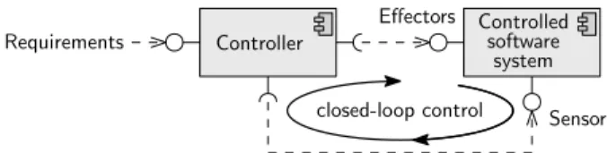
As software adaptation is often too complex or too costly to be performed by human operators, its automation has been the subject of intense research. Using concepts borrowed from the control of discrete-event systems [93], this research proposes the extension of software systems with closed-loop control. As shown in Fig. 1, the paradigm
involves using an external softwarecontrollerto monitor the
system and to adapt its architecture or configuration after environmental and internal changes. Inspired by the au-tonomic computing manifesto [68], [75] and by pioneering work on self-adaptive software [73], [88], this research has been very successful [122]. Over the past decade, numerous research projects proposed architectures [55], [78], [128] and frameworks [15], [44], [112], [127] for the engineering of self-adaptive systems. Extensive surveys of this research and its applications are available in [69], [91], [97].
In this paper, we are concerned with the use of self-adaptive software in systems with strict functional and • R. Calinescu, S. Gerasimou, I. Habli and T. Kelly are with the Department
of Computer Science at the University of York, UK.
• D. Weyns is with the Department of Computer Science of the Katholieke Universiteit Leuven, Belgium.
• M. U. Iftikhar is with the Department of Computer Science at Linnaeus University, Sweden. Effectors Controlled software system Controller Requirements Sensors closed-loop control
Fig. 1. Closed-loop control is used to automate software adaptation
non-functional requirements. A growing number of sys-tems are expected to fit this description in the near fu-ture. Service-based telehealth systems are envisaged to use self-adaptation to cope with service failures and workload variations [15], [45], [124], avoiding harm to patients. Au-tonomous robots used in applications ranging from man-ufacturing [41], [59] to oceanic monitoring [19], [56] will need to rely on self-adaptive software for completing their missions safely and effectively, without damage to, or loss of, expensive equipment. Employing self-adaptive software in these applications is very challenging, as it requires assurances about the correct operation of the software in scenarios affected by uncertainty.
Assurance has become a major concern for self-adaptive software only recently [26], [31], [37], [38], [98]. Accordingly, the research in the area is limited, and often confined to providing evidence that individual aspects of the self-adaptive software are correct (e.g. the software platform used to execute the controller, the controller functions, or the runtime adaptation decisions). However, such evidence is only one component of the established industry process for the assurance of software-based systems [11], [83], [114]. In real-world applications, assuring a software system requires
the provision of anassurance case, which standards such as
[115] define as
“a structured argument, supported by a body of evi-dence, that provides a compelling, comprehensible and valid case that a system is safe for a given application in a given environment”.
Our work addresses this discrepancy between the state of practice and the current research on assurances for self-adaptive software. To this end, we introduce a generic methodology for the joint development of trustworthy
self-adaptive software systems and their associated assurance
cases. Our methodology for the ENgineering of TRUstwor-thy Self-adaptive sofTware (ENTRUST) is underpinned by a combination of (1) design-time and runtime modelling and verification, and (2) an industry-adopted standard for the formalisation of assurance arguments [61], [105].
ENTRUST uses design-time modelling, verification and synthesis of assurance evidence for the control aspects of a self-adaptive system that are engineered before the sys-tem is deployed. These design-time activities support the initial controller enactment and the generation of a partial assurance case for the self-adaptive system. The dynamic selection of a system configuration (i.e., architecture and parameters) during the initial deployment and after internal and environmental changes involves further modelling and verification, and the synthesis of the additional assurance evidence required to complete the assurance case. These activities are fully automated and carried out at runtime.
The ENTRUST methodology is not prescriptive about the modelling, verification and assurance evidence gener-ation methods used in its design-time and runtime stages. This generality exploits the fact that the body of evidence underpinning an assurance case can combine verification evidence from activities including formal verification, test-ing and simulation. As such, ENTRUST assurance cases can use assurance evidence obtained through a combination of testing, simulation and formal verification, at both design time and runtime.
ENTRUST supports the systematic engineering and as-surance of self-adaptive systems. In line with other research on self-adaptive systems (see e.g. [97], [126]), we assume that the controlled software system from Fig. 1 already exists, and we focus on its enhancement with self-adaptation capabilities through the addition of a high-level monitor-analyse-plan-execute (MAPE) control loop. The components of the controlled software system may already support low-level, real-time adaptation to localised changes. For instance, the self-adaptive embedded system used in one of our case studies is a controlled unmanned vehicle that employs built-in low-level control to mabuilt-intabuilt-in the speed selected by its high-level ENTRUST controller. Mature approaches from the areas of robust control of discrete-event systems (e.g. [82], [93], [110], [130]) and real-time systems (e.g. [79], [84]) already exist for the engineering of such low-level control. Thus, real-time control is outside the scope of ENTRUST.
Likewise, established assurance processes are available for the non-self-adaptive aspects of software systems (e.g. [10], [11], [63], [66], [96]). We do not duplicate this work. Using these processes to construct assurance arguments for the correct design, development and operation of the controlled software system, and for the derivation, validity, completeness and formalisation of the requirements from Fig. 1 is outside the scope of our paper. Thus, ENTRUST focuses on the correct engineering of the controller and on the correct operation of self-adaptive system, assuming that the controlled system and its requirements are both correct.
The main contributions of our paper are:
1) The first end-to-end methodology for (a) engineering self-adaptive software systems with assurance evidence for the controller platform, its functions and the adapta-tion decisions; and (b) devising assurance cases whose assurance arguments bring together this evidence. 2) A novel assurance argument pattern for self-adaptive
systems, expressed in the Goal Structuring Notation (GSN) standard [61] that is widely used for assurance case development in industry [105].
3) An instantiation of our methodology whose stages are supported by the established modelling and verification tools UPPAAL [7] and PRISM [81].
These contributions include four significant extensions of complementary results from our previously separate strands of work on developing formally verified control loops [70], [71], runtime probabilistic model checking [20] and dynamic assurance cases [39]. First, the instantiation of the ENTRUST methodology is based on a formally verifiable controller architecture where the controller from [70] was extended to use probabilistic model checking at runtime [20]. Second, building on [71], we introduce a set of generic properties that ENTRUST controllers must satisfy. Third, we extend our preliminary work from [39] with a realisation of the principles of dynamic assurance case continuity, updatability, proactivity, automation and formality that we suggested in [39]. Fourth, we devise the first assurance argument pattern for self-adaptive systems. In addition, we integrate these extended building blocks into a complete methodology for the engineering of self-adaptive systems.
To ensure the generality of ENTRUST, these contribu-tions are evaluated using two case studies with differ-ent characteristics (e.g. types of system, requiremdiffer-ents and adaptation actions) and belonging to different application domains (i.e. oceanic monitoring and exchange trade). We chose for these case studies systems that have been used to evaluate related software engineering research [19], [56], [58], [101], as these systems are already known to the re-search community – one of them as an “exemplar” for the evaluation of new approaches to engineering self-adaptive systems [57].
The remainder of the paper is organised as follows. In Section 2, we provide background information on assurance cases, GSN and assurance argument patterns. Section 3 in-troduces the self-adaptive systems used in our case studies, and Section 4 describes the generic ENTRUST methodol-ogy. Sections 5 and 6 present the tool-supported ENTRUST instance and its use to develop the self-adaptive systems from the two case studies, respectively. Section 7 presents our evaluation results, which show that the methodology can be used for the effective engineering of self-adaptive systems from different domains and for the generation of dynamic assurance cases for these systems. In Section 8, we overview the existing approaches to providing assurances for self-adaptive software systems, and we compare them to ENTRUST. Finally, Section 9 concludes the paper with a discussion and a summary of future work directions.
2 P
RELIMINARIESThis section provides background information on assurance cases, introducing the assurance-related terminology and
fGoal Identifierg fContext Identifierg fJustification Identifierg
fAssumption Identifierg fStrategy Identifierg
fAway Goal Identifierg fSolution Identifierg Supported by In context of Multiplicity Optionality n Choice Uninstantiated Undeveloped Entity Entity
hGoal Statementi hContext Statementi hJustification Statementi
hStrategy Statementi hAssumption Statementi
hGoal Statementi hModule Identifieri hSolution Statementi J A
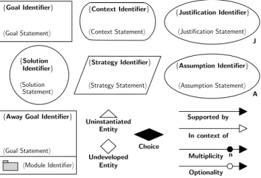
Fig. 2. Core GSN elements
concepts used in the rest of the paper. We start by defining assurance cases and their components in Section 2.1. Next, we introduce a commonly used notation for the specification of assurance cases in Section 2.2. Finally, we introduce the concept of an assurance argument pattern in Section 2.3. 2.1 Assurance Cases
An assurance case1 is a report that supports a specificclaim
about the requirements of a system [10]. As an example, the assurance case in [87] provides documented assurance that the “implementation and operation of North European Functional Airspace Block (NEFAB) is acceptably safe ac-cording to ICAO, EC and EUROCONTROL safety require-ments.” The documented assurance within an assurance
case comprises (1) evidence and (2) structured arguments
that link the evidence to the claim [10], possibly through intermediate claims.
Assurance cases are becoming mandatory for software systems used in safety-critical and mission-critical applica-tions [11], [83], [114]. They are used in domains ranging from nuclear energy [116] and medical devices [118] to air traffic control [46] and defence [115]. A growing number of assurance cases from these and other domains are openly available (e.g., [87], [117]).
The development of assurance cases comprises processes carried out at all stages of the system life cycle [114]. Re-quirements analysis evidence and design evidence demon-strate that system reliability, safety, maintainability, etc. are considered in the early stages of the life cycle. Implementa-tion, validation and verification evidence are then generated as the system is developed. Finally, evidence collected at runtime is used to update assurance cases during system maintenance.
As aptly described in [114], the assurance case must be “a living, cradle-to-grave document.” This is particularly true for self-adaptive software systems. For these systems, existing evidence needs to be continuously combined with new adaptation evidence, i.e., evidence that the system will continue to operate safely after self-adaptation activities.
1. Assurance cases developed for safety-critical systems are also calledsafety cases. In this work, we are concerned with any self-adaptive software systems that must meet strict requirements, and therefore we talk about assurance cases and assurance arguments.
Context 1 Heating system
Strategy 1 Argument based on addressing the safety of system functions Goal 1
Heating system is safe
Context 2 Control and monitor system functions
Goal 2 Control system function is safe
Goal 3
All system functions are independent Goal 2’ Monitor system function is safe Solution 1 Simulation results Solution 2 Test results Solution 3 Formal proof
Fig. 3. Example of a GSN assurance argument
2.2 Goal Structuring Notation
The assurance cases for self-adaptive systems introduced
later in the paper are devised in theGoal Structuring Notation
(GSN) [74], a community standard [61] widely used for assurance case development in industry [105]. The main GSN elements (Fig. 2) can be used to construct an argument by showing how an assurance claim (represented in GSN
by agoal) is broken down into sub-claims (also represented
by GSN goals), until eventually it can be supported by
GSN solutions (i.e., assurance evidence from verification,
testing, etc.). Strategiesare used to partition the argument
and describe the nature of the inference that exists between
a goal and its supporting goal(s). The rationale (assumptions
and justifications) for individual elements of the argument
can be captured, along with thecontext(e.g. to describe the
operational environment) in which the claims are stated. In a GSN diagram, claims are linked to strategies,
sub-claims and ultimately to solutions using ‘supported by’
con-nectives, which are rendered as lines with a solid arrowhead and declare inferential or evidential relationships. ‘Sup-ported by’ connectives may be decorated with their multi-plicity or marked as optional. The ‘in context of’ connective, rendered as a line with a hollow arrowhead, declares a contextual relationship between a goal or strategy on the one hand and a context, assumption or justification on the other hand.
Large or complex sections of the assurance argument can
be organised into modules by means of GSN away goals
referenced in the main argument and defined separately.
Finally, GSN entities can be marked as uninstantiated to
indicate that they are placeholders that need to be replaced with a concrete instantiation, and GSN goals can be marked as undeveloped to indicate that they need to be further developed into sub-goals, strategies and solutions.
As an example, Fig. 3 shows a simple GSN assurance argument for the software part of a heating system. Its root
goal (Goal 1) claims that the system is safe at all times.
This claim is partitioned into sub-claims using a strategy (Strategy 1) that addresses the safety of the two system functions (i.e. control and monitoring) separately through
n (n=#functions) Context 1
{System X}
Strategy 1 Argument based on addressing the safety of system functions Goal 1 {System X} is safe Context 2 {List of system functions} Goal 2 {Function Y} is safe Goal 4 Interactions between system functions are non-hazardous Goal 3
All system functions are independent
1 of 2
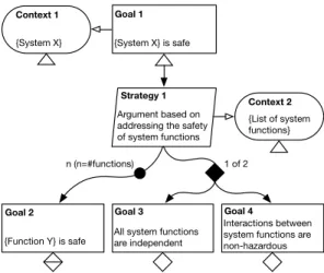
Fig. 4. Example of a GSN assurance argument pattern
sub-claimsGoal 2(for the control system) andGoal 2’(for
the monitor system), and includes sub-claim Goal 3 that
the two functions are independent. The three sub-claims are supported by three solutions comprising assurance evidence from simulation, testing and formal proof, respectively. 2.3 Assurance Argument Patterns
To reduce the significant effort required to develop assur-ance cases, in our previous work on software assurassur-ance [63], [65] we collaborated to the creation of a catalog of reusable GSNassurance argument patterns[64]. Each pattern considers the contribution made by the software to system hazards for a particular class of systems and scenarios. The GSN elements of a pattern that are generic to the entire class are fully developed and instantiated, whereas the entities that are specific to each system and scenario within the class are left undeveloped and/or uninstantiated.
As an example, Fig. 4 depicts an assurance argument pattern that is instantiated by the GSN assurance argument
from Fig. 3. The elements surrounded by curly brackets ‘{’
and ‘}’ in the pattern must beinstantiated for each
assur-ance argument based on the pattern, as further indicated by the triangular ‘uninstantiated’ symbol under the GSN
entities that contain them. Goal 2 is marked with both
this ‘uninstantiated’ symbol (because it contains elements in curly brackets) and a diamond-shaped ‘undeveloped’
symbol (because, like for the ‘choice’ sub-claimsGoal 3and
Goal 4, additional GSN entities must be added underneath to complete the assurance argument); the two symbols are
rendered overlapping underGoal 2.
In this paper, we devise a new assurance argument pat-tern, which is applicable to self-adaptive software systems.
3 S
ELF-
ADAPTIVES
YSTEMSU
SED IN THEC
ASES
TUDIESThis section introduces the self-adaptive software systems from the two case studies used to illustrate and evaluate our methodology. To assess the generality of ENTRUST, we chose different types of systems from different do-mains. The first system, introduced in Section 3.1, is an embedded unmanned underwater vehicle (UUV) system from the oceanic monitoring domain. The second system,
TABLE 1
Comparison of systems used to assess the generality of ENTRUST
UUV FX
Type embedded system service-based system
Domain oceanic monitoring exchange trade
Requirements throughput, resource use,
cost, safety reliability, response time,cost, safety Sensor data UUV sensor measure- service response time
ment rate and reliability
Adaptation switch sensors on/off, change service instance
actions change speed
Uncertainty continuous-time stochas- discrete-time stochastic modelling tic model of UUV sensors model of system
presented in Section 3.2, is a service-based system from the foreign exchange (FX) trade domain. Table 1 lists several additional characteristics that differ significantly between the two systems. These characteristics include the types of requirements, sensor data and adaptation actions of the sys-tems, and the types of models whose verification underpins their self-adaptation decisions.
3.1 Unmanned Underwater Vehicle (UUV) System The self-adaptive UUV embedded system is adapted from [56]. UUVs are increasingly used in a wide range of oceanographic and military tasks, including oceanic surveil-lance (e.g., to monitor pollution levels and ecosystems), undersea mapping and mine detection. Limitations due to their operating environment (e.g., impossibility to maintain UUV-operator communication during missions and unex-pected changes) require that UUV systems are self-adaptive. These systems are often mission critical (e.g., when used for mine detection) or business critical (e.g., they carry expensive equipment that should not be lost).
The self-adaptive system we use consists of a UUV deployed to carry out a data gathering mission. The UUV is
equipped withn 1on-board sensors that can measure the
same characteristic of the ocean environment (e.g., water current, salinity or temperature). When used, the sensors take measurements with different, variable ratesr1,r2, . . . ,
rn. The probability that each sensor produces measurements
that are sufficiently accurate for the purpose of the mission
depends on the UUV speed sp, and is given by p1, p2,
. . . , pn. For each measurement taken, a different amount
of energy is consumed, given bye1,e2, . . . ,en. Finally, the
nsensors can be switched on and off individually (e.g., to
save battery power when not required), but these operations
consume an amount of energy given by eon
1 , eon2 , . . . , eonn andeo↵
1 ,eo2↵, . . . ,eon↵, respectively. The UUV must adapt to
changes in the sensor measurement ratesr1,r2, . . . ,rn and
to sensor failures by dynamically adjusting:
(a) the UUV speedsp
(b) the sensor configurationx1,x2, . . . ,xn (wherexi = 1if
thei-th sensor is on andxi = 0otherwise)
in order to meet the quality-of-service requirements below: R1 (throughput): The UUV should take at least 20
mea-surements of sufficient accuracy for every 10 metres of mission distance.
R2 (resource usage): The energy consumption of the sen-sors should not exceed 120 Joules per 10 surveyed me-tres.
R3 (cost): If requirements R1 and R2 are satisfied by mul-tiple configurations, the UUV should use one of these configurations that minimises the cost function
cost=w1E+w2sp 1, (1)
where E is the energy used by the sensors to survey
a 10m mission distance, and w1, w2 > 0 are weights
that reflect the relative importance of carrying out the mission with reduced battery usage and completing the mission faster.2
R4 (safety): If a configuration that meets requirementsR1–
R3 is not identified within 2 seconds after a sensor
rate change, the UUV speed must be reduced to 0m/s. This ensures that the UUV does not advance more than the distance it can cover at its maximum speed within 2 seconds without taking appropriate measurements, and waits until the controller identifies a suitable con-figuration (e.g., after the UUV sensors recover) or new instructions are provided by a human operator.
3.2 Foreign Exchange Trading System
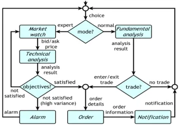
The service-based system from the area of foreign exchange trading is taken from our recent work in [58]. This system, which we anonymise as FX for confidentiality reasons, is used by an European foreign exchange brokerage company. The FX system implements the workflow shown in Fig. 5 and described below.
An FX customer (called a trader) can use the system in
two operation modes. In the expert mode, FX executes a
loop that analyses market activity, identifies patterns that satisfy the trader’s objectives, and automatically carries
out trades. Thus, the Market watch service extracts
real-time exchange rates (bid/ask price) of selected currency
pairs. This data is used by aTechnical analysis service that
evaluates the current trading conditions, predicts future price movement, and decides if the trader’s objectives are:
(i) “satisfied” (causing the invocation of an Order service
to carry out a trade); (ii) “unsatisfied” (resulting in a new
Market watch invocation); or (iii) “unsatisfied with high
variance” (triggering an Alarmservice invocation to notify
the trader about discrepancies/opportunities not covered by
the trading objectives). In thenormalmode, FX assesses the
economic outlook of a country using aFundamental analysis
service that collects, analyses and evaluates information such as news reports, economic data and political events, and provides an assessment on the country’s currency. If
satisfied with this assessment, the trader can use theOrder
service to sell or buy currency, in which case aNotification
service confirms the completion of the trade. We assume that the FX system has to dynamically select third-party implementations for each service from Fig. 5, in order to meet the following system requirements:
2. Cost (orutility) functions that employ weights to combine several performance, reliability, resource use and other quality attributes of software—accounting for differences in attribute value ranges and relative importance—are extensively used in self-adaptive software systems (e.g. [15], [44], [55], [97], [121]).
Fig. 5. Foreign exchange trading (FX) workflow
R1 (reliability): Workflow executions must complete suc-cessfully with probability at least 0.9.
R2 (response time): The total service response time per workflow execution must be at most 5s.
R3 (cost): If requirements R1 and R2 are satisfied by multi-ple configurations, the FX system should use one of these configurations that minimises the cost function:
cost=w1price+w2time, (2)
where price and time represent the total price of the
services invoked by a workflow execution and the re-sponse time for a workflow execution, respectively, and
w1, w2>0are weights that encode the desired trade-off
between price and response time.
R4 (safety): If a configuration that ensures requirements
R1–R3 cannot be identified within 2s after a change in
service characteristics is signalled by the sensors of the
self-adaptive FX system, the Orderservice invocation is
bypassed, so that the FX system does not carry out any trade that might be based on incorrect or stale data. Note that requirements R1–R3 express two constraints and an optimisation criterion that are qualitatively different from those specified by the requirements from our first case study (cf. Section 3.1). Nevertheless, our tool-supported instance of the ENTRUST methodology enabled the development of the self-adaptive FX system as described in Section 6.
4 T
HEENTRUST M
ETHODOLOGYThe ENTRUST methodology supports the systematic engi-neering and assurance of self-adaptive systems based on monitor-analyse-plan-execute (MAPE) control loops. This is by far the most common type of control loop used to devise self-adaptive software systems [14], [37], [38], [44], [69], [80], [85], [97]. The engineering of self-adaptive systems based on essentially different control techniques, such as the control theoretical paradigm [100], as for example proposed in [50], is not supported by our methodology.
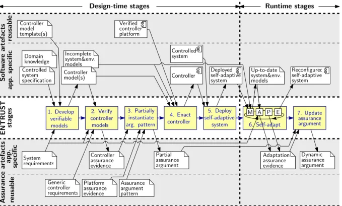
ENTRUST comprises the tool-supported design-time stages and the automated runtime stages shown in Fig. 6, and is underpinned by two key principles:
1. Develop verifiable models 2. Verify controller models 4. Enact controller 5. Deploy self-adaptive system 3. Partially instantiate arg. pattern 7. Update assurance argument ENTRUS T st age s S of tw ar e ar te fac ts ap p . sp ec ifi c re u sab le Incomplete system&env. models Controller model(s) Verified controller platform ap p . sp ec ifi c re u sab le Controller assurance evidence Assurance argument pattern Controller Dynamic assurance argument Adaptation assurance evidence M A P E 6. Self-adapt Deployed self-adaptive system Up-to-date system&env. models Reconfigured self-adaptive system Design-time stages A ss u ran ce ar te fac ts System requirements Controller model template(s) Generic controller requirements Domain knowledge Controlled system specification Platform assurance evidence Partial assurance argument Runtime stages Controlled system
Fig. 6. Stages and key artefacts of the ENTRUST methodology. In line with the two principles underpinning the methodology, its first stage involves the development of verifiable models for the controller, controlled system and environment of the self-adaptive system used throughout the remaining stages, and multiple stages reuse application-independent software and assurance artefacts.
1) Model-driven engineering is essential for developing trustwor-thy self-adaptive systems and their assurance cases.As em-phasised in the previous section, model-based analysis, simulation, testing and formal verification—at design time and during reconfiguration—represent the main sources of assurance evidence for self-adaptive software. As such, both the design-time and the runtime stages of our methodology are model driven. Models of the struc-ture and behaviour of the functional components, con-troller and environment are the basis for the engineering and assurance of ENTRUST self-adaptive systems. 2) Reuse of application-independent software and assurance
arte-facts significantly reduces the effort and expertise required to develop trustworthy self-adaptive systems. Assembling an assurance case for a software system is a costly process that requires considerable effort and expertise. There-fore, the reuse of both software and assurance artefacts is essential for ENTRUST. In particular, the reuse of application-independent controller components and of templates for developing application-specific controller elements also enables the reuse of assurance evidence that these software artefacts are trustworthy.
The ENTRUST stages and their exploitation of these two principles are described in the remainder of this section. 4.1 Design-time ENTRUST Stages
4.1.1 Stage 1: Development of Verifiable Models
In ENTRUST, the engineering of a self-adaptive system with the architecture from Fig. 1 starts with the development of models for:
1) The controller of the self-adaptive system;
2) The relevant aspects of the controlled software system and its environment.
A combination of structural and behavioural models may be produced, depending on the evidence needed to assem-ble the assurance case for the self-adaptive system under development. ENTRUST is not prescriptive in this respect.
However, we require that these models are verifiable, i.e.,
that they can be used in conjunction with methods such as model checking or simulation, to obtain evidence that the controller and the self-adaptive system meet their require-ments. As an example, finite state transition models may be produced for the controllers of our UUV and FX systems from Section 3, enabling the use of model checking to verify that these controllers are deadlock free.
The verifiable models are application-specific. As
illus-trated in Fig. 6, their development requires domain
knowl-edge,3 is based on acontrolled system specification, and is
in-formed by thesystem requirements. As in other areas of
soft-ware engineering, we envisage that tool-supported methods will typically be used to obtain these models. However, their manual development or fully automated synthesis are not precluded by ENTRUST.
In line with the “reuse of artefacts” principle, ENTRUST exploits the fact that the controllers of self-adaptive sys-tems implement the established MAPE workflow, and uses
application-independentcontroller model template(s)to devise
the controller model(s). These templates model the generic aspects of the MAPE workflow and contain placeholders for the application-specific elements of an ENTRUST controller. 3. The ENTRUST software and assurance artefacts that appear in italicsin the text are also shown in Fig. 6.
Given the environmental and internal uncertainty that
characterises self-adaptive systems, only incomplete system
and environment modelscan be produced in this ENTRUST stage. These incomplete models may include unknown or estimated parameters, nondeterminism (i.e., alternative options whose likelihoods are unknown), parts that are missing, or some combination of all of these. For example, parametric Markov chains may be devised to enable the runtime analysis of the requirements for our UVV and FX systems detailed in Sections 3.1 and 3.2, respectively, by means of probabilistic model checking or simulation.
4.1.2 Stage 2: Verification of Controller Models
The main role of the second ENTRUST stage is to produce
controller assurance evidence, i.e., compelling evidence that a controller based on the controller model(s) from Stage 1 will satisfy a set ofgeneric controller requirements. These are requirements that must be satisfied in any self-adaptive sys-tem (e.g., deadlock freeness) and are predefined in a format compatible with that of the controller model templates and with the method that will be used to verify the controller models. For example, if labelled transition systems are used to model the controller and model checking to establish its correctness as in [41], [42], these generic controller require-ments can be predefined as temporal logic formulae.
The controller assurance evidence must include evidence that the system requirements for application-specific fail-safe operating mode(s) are always satisfied. In this way, a minimal assurance case is always available for the scenario when the runtime assurance evidence for other system re-quirements cannot be obtained and the self-adaptive system needs to switch to a degraded, failsafe mode of operation. Several fallback levels as proposed in [41] can also be supported in this way, with only the most degraded fallback level ensured through assurance evidence obtained in this ENTRUST stage. For example, requirements R4 of our UUV and FX systems from Section 3 specify failsafe operating modes for the two systems, so we will need to show that these requirements are always met.
The assurance evidence generated in this stage of the methodology may be obtained using a range of methods that include formal verification, theorem proving and sim-ulation. The methods that can be used depend on the types of models produced in the previous ENTRUST stage, and on the generic controller requirements and system require-ments for which assurance is sought. The availability of tool support in the form of model checkers, theorem provers, SMT solvers, domain-specific simulators, etc. will influence the choice of these methods.
Preparing the design-time models, i.e., developing ver-ifiable models and verifying the controller models, comes with a cost. This cost can be reduced by using tool-supported methods and by exploiting reusable application-independent software, as done by the related approaches described in Section 8. Furthermore, these related ap-proaches that only provide a fraction of the assurances that ENTRUST achieves (as detailed when we discuss related work in Section 8) operate with design-time models that re-quire a comparable effort to specify the models and provide the controller assurance evidence.
4.1.3 Stage 3: Partial Instantiation of Assurance Argument Pattern
This ENTRUST stage uses the controller assurance evidence from Stage 2 to support the partial instantiation of a generic
assurance argument pattern for self-adaptive software. As explained in Section 2.3, this pattern is an incomplete as-surance argument containing placeholders for the system-specific assurance evidence. A subset of the placeholders correspond to the controller assurance evidence obtained in Stage 2, and are therefore instantiated using this evidence.
The result is a partial assurance argument, which still
con-tains placeholders for the assurance evidence that cannot be obtained until the uncertainties associated with the self-adaptive system are resolved at runtime.
For example, the partial assurance argument for our UUV and FX systems should contain evidence that their controllers are deadlock free and that their failsafe require-ments R4 are always satisfied. These requirerequire-ments can be verified at design time. In contrast, requirements R1–R3 for the two systems cannot be verified until runtime, when the controller acquires information about the measurement rates of the UUV sensors and the third-party services avail-able for the FX operations, respectively. Assurance evidence that requirements R1–R3 are satisfied can only be obtained at runtime.
In addition to the two types of placeholders, the as-surance argument pattern used as input for this stage in-cludes assurance evidence that is application independent. In particular, it includes evidence about the correct opera-tion of the verified controller platform, i.e. the software that implements application-independent controller
functional-ity used to execute the ENTRUST controllers. Thisplatform
assurance evidenceis reusable across self-adaptive systems.
4.1.4 Stage 4: Enactment of the Controller
This ENTRUST stage assembles the controller of the
self-adaptive system. The process involves integrating the ver-ified controller platform with the application-specific con-troller elements, and with the sensors and effectors that interface the controller with the controlled software system from Fig. 1.
The application-specific controller elements must be de-vised from the verified controller models, by using a trusted model-driven engineering method. This can be done using
model-to-text transformation, a method that employs a trusted
model compilerto generate a low-level executable represen-tation of the controller models. Alternatively, the ENTRUST verified controller platform may include a trusted virtual
machine4 able to directly interpret and run the controller
models. The second, model interpretationmethod [104], has
the advantage that it eliminates the need to generate con-troller code and to provide additional assurances for it.
4.1.5 Stage 5: Deployment of the Self-Adaptive System
In the last design-time stage, the integrated controller and controlled components of the self-adaptive system are installed, preconfigured and activated by means of an 4. Throughout the paper, the term “virtual machine” refers to a software component capable to interpret and execute controller models, much like a Java virtual machine executes Java code.
application-specific process. The pconfiguration is re-sponsible for setting the deployment-specific parameters and architectural aspects of the system. For example, the pre-configuration of the UUV system from Section 3.1 in-volves selecting the initial speed and active sensor set for the UUV, whereas for the FX system from Section 3.2 it involves choosing initial third-party implementations for each FX service.
Thedeployed self-adaptive systemwill be fully configured and a complete assurance argument will be available only after the first execution of the MAPE control loop. This execution is typically triggered by the system activation, to ensure that the newly deployed self-adaptive system takes into account the current state of its environment as described next.
4.2 Runtime ENTRUST Stages
4.2.1 Stage 6: Self-adaptation
In this ENTRUST stage, the deployed self-adaptive system is dynamically adjusting its parameters and architecture in line with observed internal and environmental changes. To this end, the controller executes a typical MAPE loop that monitors the system and its environment, using the information obtained in this way to resolve the “unknowns” from the incomplete system and environment models. The
resulting up-to-date system and environment models enable
the MAPE loop to analyse the system compliance with its requirements after changes, and to plan and execute suitable reconfigurations if necessary.
Whenever the MAPE loop produces a reconfigured
self-adaptive system, its analysis and planning steps generate
adaptation assurance evidence confirming the correctness of the analysis results and of the reconfiguration plan devised on the basis of these results. This assurance evidence is a by-product of analysis and planning methods that may include runtime verification, simulation and runtime model check-ing. Irrespective of the methods that produce it, the adapta-tion assurance evidence is essential for the development of a complete assurance argument in the next ENTRUST stage.
4.2.2 Stage 7: Synthesis of Dynamic Assurance Argument
The final ENTRUST stage uses the adaptation correct-ness evidence produced by the MAPE loop to fill in the placeholders from the partial assurance argument, and to devise the complete assurance case for the reconfigured self-adaptive system. For example, runtime evidence that requirements R1–R3 of the UUV and FX systems from Section 3 are met will be used to complete the remaining placeholders from their partial assurance arguments. Thus,
an ENTRUST assurance case is underpinned by a dynamic
assurance argumentthat is updated after each reconfiguration of the system parameters and architecture. This assurance case captures both the full assurance argument and the evidence that justifies the active configuration of the self-adaptive system.
The ENTRUST assurance case versions generated for every system reconfiguration have two key uses. First, they allow decision makers and auditors to understand and assess the present and past versions of the assurance case. Second, they allow human operators to endorse major
reconfiguration plans in human-supervised self-adaptive systems. This type of self-adaptive systems is of particular interest in domains where human supervision represents an important risk mitigation factor or may be required by regulations. As an example, UK Civil Aviation Authority regulations [113] permit self-adaptation in certain functions (e.g., power management, flight management and collision avoidance) of unmanned aircraft of no more than 20 kg provided that the aircraft operates within the visual line of sight of a human operator.
5 T
OOL-S
UPPORTEDI
NSTANCE OFENTRUST
This section presents an instance of ENTRUST in which the stages described in Section 4 are supported by the modelling and verification tools UPPAAL [7] and PRISM [81]. We start with an overview of this tool-supported ENTRUST instance in Section 5.1, followed by a description of each of its stages in Section 5.2.
5.1 Overview
The ENTRUST methodology can be used with different combinations of modelling, verification and controller en-actment methods, which may employ different self-adaptive system architectures and types of assurance evidence. This section presents a tool-supported instance of ENTRUST that uses one such combination of methods. We developed this instance of the methodology with the aim to validate ENTRUST and to ease its adoption.
Our ENTRUST instance supports the engineering of self-adaptive systems with the architecture shown in Fig. 7. The reusable verified controller platform at the core of this architecture comprises:
1) A Trusted Virtual Machine that directly interprets and executes models of the four steps from the MAPE control
loop5(i.e., the ENTRUST controller models).
2) A Probabilistic Verification Engine that is used to verify stochastic models of the controlled system and its envi-ronment during the analysis step of the MAPE loop.
Using theTrusted Virtual Machinefor controller model
inter-pretation eliminates the need for a model-to-text transfor-mation of the controller models into executable code, which is a complex, error-prone operation. Not having to devise this transformation and to provide assurance evidence for it are major benefits of our ENTRUST instance. Although we still need assurance evidence for the virtual machine, this was obtained when we developed and verified the virtual
machine,6 and is part of the reusable platform assurance
evidencefor the ENTRUST instance.
The Probabilistic Verification Engine consists of the verification libraries of the probabilistic model checker PRISM [81] and is used by the analysis step of the MAPE control loop. As such, our ENTRUST instance works with:
5. Hence the controller models are depicted as software components in Fig. 7.
6. This assurance evidence is in the form of a comprehensive test suite and a report describing its successful execution by the virtual machine, both of which are available on our ENTRUST project website at https://www-users.cs.york.ac.uk/simos/ENTRUST/.
Controller
Controlled software system
Sensors Effectors
Probabilistic Verification Engine
Trusted Virtual Machine Monitor Analyzer Planner Executor
Controller models
Verified controller platform Knowledge Repository Partial assurance argument Adaptation assurance evidence Dynamic assurance argument Stochastic system&env. models System requirements
Fig. 7. Architecture of an ENTRUST self-adaptive system
1) Stochastic finite state transition models of the controlled system and the environment, defined in the PRISM high-level modelling language. Incomplete versions of these models are devised in Stage 1 of ENTRUST, and have their unknowns resolved at runtime. All types of models that PRISM can analyse are supported, including discrete- and continuous-time Markov chains (DTMCs and CTMCs), Markov decision processes (MDPs) and probabilistic automata (PAs).
2) Runtime-assured system requirements expressed in the appropriate variant of probabilistic temporal logic, i.e., probabilistic computation tree logic (PCTL) for DTMCs, MDPs and PAs, and continuous stochastic logic (CSL) for CTMCs.
This makes our instantiation of the generic ENTRUST methodology applicable to self-adaptive systems whose non-functional (e.g., reliability, performance, resource usage and cost-related) requirements can be specified in the above logics, and whose behaviour related to these requirements can be described using stochastic models. As shown by the recent work of multiple research groups (e.g., [15], [20], [24], [28], [45], [48], [51], [92], [107]), this represents a broad and important class of self-adaptive software that includes a wide range of service-based systems, web applications, resource management systems, and embedded systems.
Also developed in Stage 1 of ENTRUST, the four con-troller models form an application-specific network of inter-acting timed automata [2], and are expressed in the mod-elling language of the UPPAAL verification tool suite [7].
Accordingly, UPPAAL is used in Stage 2 of ENTRUST to verify the compliance of the controller models with
the generic controller requirements and with any system requirements that can be assured at design time. These re-quirements are defined in computation tree logic (CTL) [32]. In Stage 3 of our ENTRUST instance, a partial assurance argument is devised starting from an assurance argument
pattern represented ingoal structuring notation(GSN) [74].
The controller enactment from Stage 4 involves integrat-ing the timed-automata controller models with our verified controller platform.
In Stage 5 of ENTRUST, the controlled software system and its enacted controller are deployed, together with a
Knowledge Repository that supports the operation of the controller. Initially, this repository contains: (i) the partial assurance argument from Stage 3; (ii) the system require-ments to be assured at runtime; and (iii) the (incomplete) stochastic system and environment models from Stage 1.
During the execution of the MAPE loop in Stage 6 of
ENTRUST, the Monitor obtains information about the
sys-tem and its environment throughSensors. This information
is used to resolve the unknowns from the stochastic models of the controlled system and its environment. Examples of such unknowns include probabilities of transition to ‘failure’ states for a DTMC, MDP or PA, rates of transition to ‘success’ states for a CTMC, and sets of states and transitions modelling certain system behaviours. After each update of
the stochastic system and environment models, theAnalyzer
reverifies the compliance of the self-adaptive system with its runtime-assured requirements. When the requirements
are no longer met, theAnalyzeruses the verification results
to identify a new system configuration that restores this compliance, or to find out that such a configuration does not exist and to select a predefined failsafe configuration. The step-by-step actions needed to achieve the new
configura-tion are then established by thePlannerand implemented by
theExecutorthrough theEffectorsof the controlled system.
Using theProbabilistic Verification Engineenables the
An-alyzerandPlannerto produce assurance evidence justifying their selection of new configurations and of plans for tran-sitioning the system to these configurations, respectively. This adaptation assurance evidence is used to synthesise a fully-fledged, dynamic GSN assurance argument in Stage 7 of our ENTRUST instance. As indicated in Fig. 7, versions of the adaptation assurance evidence and of the dynamic assurance argument justifying each reconfiguration of the
self-adaptive system are stored in theKnowledge Repository.
The implementation of the ENTRUST stages in our tool-supported instance of the methodology is summarised in Table 2 and described in further detail in Section 5.2. 5.2 Stage Descriptions
5.2.1 Development of Verifiable Models
Controller models.We devised two types of templates for
the four controller models from Fig. 7: (i) event triggered,
in which the monitor automaton is activated by a sensor-generated signal indicating a change in the managed system
or the environment; and (ii) time triggered, in which the
monitor is activated periodically by an internal clock. The event-triggered automaton templates are shown in Fig. 8 using the following font and text style conventions:
TABLE 2
Stages of the tool-supported instance of the ENTRUST methodology
Stage Type Description Supporting tool(s)
1 tool supported Timed automata controller models developed from UPPAAL templates UPPAAL
Incomplete stochastic models of the controlled system and environment
developed based on system specification and domain knowledge PRISM
2 tool supported Controller models verified to obtain controller assurance evidence UPPAAL
3 manual Partial assurance argument devised from GSN assurance argument pattern –
4 manual Controller enacted by integrating the verified controller models and platform –
5 manual Controlled system, controller and knowledge repository deployed –
6 automated MAPE control loop continually executed to ensure the system requirements PRISM & ENTRUST
controller platform
7 automated GSN dynamic assurance argument generated ENTRUST controller
platform (a) Monitor WaitP plannerCleanup() Application-specific planner Plan PlanCreated startPlanning? startExecuting! (c) Planner executorInit() executorCleanup() planExecuted! Application-specific executor WaitE Execute PlanExecuted startExecuting? <executorSignal1!> <executorSignalm!> … … … (d) Executor startAnalysis!
WaitM ProcessSensorData CheckM
process() !analysisRequired() monitorCleanup() <sensorSignal1?> <sensorSignaln?> .. . MonitorFinished analysisRequired() StartAnalysis Key: Automaton state State transition analysisRequired() Guard analyse() startAnalysis! Action startAnalysis? Sent signal Received signal Initial state Atomic proposition PlanCreated time=0 startPlanning! startAnalysis? WaitA CheckA Analyse StartVerif analyse() adaptationRequired() EndVerif verify! verifDone? !adaptationRequired() Adapt analyserCleanup() AnalysisFinished (b) Analyzer WaitVerif time!MAX_TIME time>MAX_TIME useFailsafeConfig()
Fig. 8. Event-triggered MAPE model templates
• Sans-serif fontis used to annotate states with the atomic
propositions (i.e. boolean properties) that hold in those
states, e.g.PlanCreatedfrom the Planner automaton;
• Italics text is used for the guards that annotate state transitions with the conditions which must hold for
the transitions to occur, e.g.timeMAX TIMEfrom the
Analyzer automaton;
• State transitions are additionally annotated with the
actions executed upon taking the transitions, and these actions are also shown in sans-serif font, e.g.time=0 to
initialise a timer in the Monitor automaton;
• Bold text is used for the synchronisation channels be-tween two automata—these channels are specified as pairs comprising a ‘!’-decorated sent signal and a ‘?’-decorated received signal with the same name, e.g., startAnalysis!andstartAnalysis?from the monitor and analyzer automata, respectively. The two transitions as-sociated with a synchronisation channel can only be taken at the same time.
Finally, signals in angle brackets ‘hi’ are placeholders for
application-specific signal names, and guards and actions decorated with brackets ‘()’ represent application-specific C-style functions.
To specialise these model templates for a particular
system and application, software engineers need: (a) to replace the signal placeholders with real signal names; (b) to define the guard and action functions; and (c) to devise the automaton regions shaded in Fig. 8. For example, for the monitor automaton the engineers first need to replace the placeholders hsensorSignal1?i, . . . , hsensorSignaln?i with sensor signals announcing relevant changes in the managed
system. They must then implement the functionsprocess(),
analysisRequired()andmonitorCleanup(), whose roles are to process the sensor data, to decide if the change specified by this data requires the “invocation” of the analyzer through the startAnalysis! signal, and to carry out any cleanup that may be required, respectively. Details about the other automata from Fig. 8 are available on our project website, which also provides implementations of these MAPE model templates in the modelling language of the UPPAAL verifi-cation tool suite [7].
Parametric stochastic models. These models used by the ENTRUST control loop at runtime are application specific, and need to be developed from scratch. Their parameters correspond to probabilities or rates of transition between model states, and are continually estimated at runtime, based on change information provided by the sensors of the controlled system. As such, the verification of these mod-els at runtime enables the ENTRUST analyzer to identify
TABLE 3
Stochastic models supported by the ENTRUST instance, with citations of representative research that uses them in self-adaptive systems
Type of stochastic model Non-functional
require-ment specification logic Discrete-time Markov chains
[15], [23], [45], [47], [48], [60] PCTL
a, LTLb, PCTL*c
Markov decision processes [51] PCTLa, LTLb, PCTL*c
Probabilistic automata [21], [72] PCTLa, LTLb, PCTL*c
Continuous-time Markov chains
[19], [22], [56] CSL
d
Stochastic games [27], [28] rPATLe
aProbabilistic Computation Tree Logic [9], [62] bLinear Temporal Logic [90]
cPCTL* is a superset of PCTL and LTL dContinuous Stochastic Logic [3], [4]
ereward-extended Probabilistic Alternating-time Temporal Logic [29]
configurations it can use to meet the system requirements after unexpected changes, as described in detail in [15], [20], [22], [45], [47]. The types of stochastic models supported by our ENTRUST instance are shown in Table 3. As illustrated by the research work cited in the table, the temporal logics used to express the properties of these models support the specification of numerous performance, reliability, safety, resource usage and other non-functional requirements that recent surveys propose for self-adaptive systems [31], [120]. To ensure the accuracy of the stochastic models de-scribed above, ENTRUST can rely on recent advances in devising these models from logs [60], [89] and UML activity diagrams [17], [53], and in dynamically and accurately up-dating their parameters based on sensor-provided runtime observations of the controlled system [16], [23], [45], [49].
5.2.2 Verification of Controller Models
During this ENTRUST stage, a trusted model checker is used to verify the network of MAPE automata devised in the previous section. This verification yields evidence that the MAPE models satisfies a set of key safety and live-ness properties that include both generic and application-specific properties. Table 4 shows a non-exhaustive list of generic properties that we assembled for the current version of ENTRUST. Although these properties are application-independent, verifying that an ENTRUST controller sat-isfies them is possible only after its application-specific MAPE models were devised. This involves completing the application-specific parts of the planner and executor
au-tomata, and implementing the functions for theguardsand
actionsfrom all the model templates.
Additionally, automata that simulate the controller sen-sors, runtime probabilistic verification engine and effectors from Fig. 7 need to be defined to enable this verification. The sensors, verification engine and effectors automata have to synchronise with the relevant monitor, analyzer and executor signals, respectively. The sensors automaton and verification automaton also have to exercise the possible paths through the monitor, analyzer and planner automata (and indirectly the executor automaton). To this end, they can nondeterministically populate the knowledge reposi-tory with data that satisfies all the different guard combina-tions. Alternatively, a finite collection of the two automata
can be used to verify subsets of all possible MAPE paths, as long as the union of all such subsets covers the entire behaviour space of the MAPE network of automata.
Note that these application-specific elements of the MAPE automata are much larger than the application-independent elements from the MAPE model templates. Therefore, we do not use compositional model checking [33], [72] to verify the two parts of the MAPE automata separately, with the application-independent elements ver-ified once and for all. Such an approach would increase the complexity of the verification task (e.g. by requiring the identification and verification of less intuitive “assump-tions” [34] that the application-specific parts of the automata need to “guarantee”) without any noticeable reduction in the verification time, almost all of which would be required to verify the application-specific automata elements.
5.2.3 Partial Instantiation of Assurance Argument Pattern
We used theGoal Structuring Notation (GSN) introduced in
Section 2.2 to devise a reusable assurance argument pattern
(cf. Section 2.3) for self-adaptive software. Unlike all existing assurance argument patterns [64], our new pattern captures the fact that for self-adaptive software the assurance pro-cess cannot be completed at design time. Instead, it is a continual process where some design features and code elements are dynamically reconfigured and executed during self-adaptation. As such, the detailed claims and evidence for meeting the system requirements must vary with self-adaption, and thus ENTRUST assurance cases must evolve dynamically at runtime.
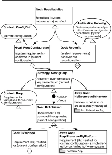
The ENTRUST assurance argument pattern is shown in
Fig. 9. Its root goal, ReqsSatisfied, states that the system
requirements are satisfied at all times. These requirements are typically allocated to the software from the higher-level system analysis process, so the justifications of their deriva-tion, validity and completeness are addressed as part of the overall system assurance case (which is outside the scope
of the software assurance case).ReqsSatisfiedis supported
by a sub-claim based on (i.e. in the context of) the current
configuration (ReqsConfiguration) and by a reconfiguration
sub-claim (Reconfig). That is, the pattern shows that we
are guaranteeing that the current configuration satisfies the requirements (in the absence of changes) and that the ENTRUST controller will plan and execute a reconfiguration that will satisfy these requirements (should a change occur). The pattern justifies how the system requirements are
achieved for each configuration by using a sub-goal
Rx-Achievedfor each requirement Rx. Further, a new config-uration has the potential to introduce erroneous behaviours (e.g., deadlocks). The justification for the absence of these
er-rors is provided via the away goalNoErroneousBehaviour
(described below). The pattern concludes with the goals RxVerified and ReqsPreservedByPlatform, which justify the verification and the implementation of the formalised
requirements, respectively. The away goal
ReqsPreserved-ByPlatform confirms that the controlled system handles correctly the reconfiguration commands received through effectors. This away goal is obtained using standard assur-ance processes, which are outside the scope of this paper.
As shown Fig. 10, the NoErroneousBehaviour away
TABLE 4
Generic properties that should be satisfied by an ENTRUST controller
ID Informal description Specification in computation tree logic (CTL) [32]
P1 The ENTRUST controller is deadlock free. A⇤not deadlock
P2 Whenever analysis is required, the Analyser eventually
carries out this action. A⇤(Monitor.StartAnalysis!A⌃Analyzer.Analyse)
P3 Whenever the system requirements are violated, a
step-wise reconfiguration plan is eventually assembled. A⇤(Analyzer.Adapt!A⌃Planner.PlanCreated)
P4 Whenever a stepwise plan is assembled, the Executor
eventually implements it. A⇤(Planner.PlanCreated!A⌃Executor.PlanExecuted)
P5 Whenever the Monitor starts processing the received
data, it eventually terminates its execution. A⇤(Monitor.ProcessSensorData!A⌃Monitor.Finished)
P6 Whenever the Analyser begins the analysis, it eventually
terminates its execution. A⇤(Analyzer.Analyse!A⌃Analyzer.AnalaysisFinished)
P7 A plan is eventually created, each time the Planner starts
planning. A⇤(Planner.Plan!A⌃Planner.PlanCreated)
P8 Whenever the Executor starts executing a plan, the plan
is eventually executed. A⇤(Executor.Execute!A⌃Executor.PlanExecuted)
P9 Whenever adaptation is required, the current
configura-tion and the best configuraconfigura-tion differ. A⇤(Analyzer.Adapt!currentConfig != newConfig)
number of reqs
J Justification: Reconfig Systemsupportsreconfigu- ration ifcurrentconfiguration cannotmeet {system requirements} Context: ConfigDef {current configuration} Goal: ReqsSatisfied formalised {system requirements} satisfied Goal: ReqsConfiguration {system requirements} achieved in {current configuration} Strategy: ConfigReqs Argument over formalised requirements for {current configuration}
Goal: RxAchieved Requirement {Rx} achieved through using {current configuration}
Away Goal:
NoErroneousBehaviour Erroneous behaviours are acceptably managed
Err. Behaviour Arg. Context: Reqs
Requirements formalised for {current configuration}
Goal: RxVerified Requirement {Rx} verified for {current configuration}
Away Goal:
ReqsPreservedByPlatform Requirement {Rx} verified for {current configuration} is implemen-ted by controlled software system
Platform Arg. Goal: Reconfig {system requirements} achieved via reconfiguration
Fig. 9. ENTRUST assurance argument pattern.
sub-claim uses the goalsFMsIdentified and ReqsDerived
to state that the relevant “failure modes” for the self-adaptive system have been identified and that the sys-tem requirements fully address these failure modes. We leave the two goals undeveloped, as they are achieved using standard requirements engineering and assurance
practices. The EngErrorsAbsent sub-claim states that the
engineering of the self-adaptive system does not
intro-duce errors in the context of the ENTRUST reusable arte-facts (i.e., of our trusted virtual machine and probabilistic verification engine) and of the generic properties that an
ENTRUST controller has to satisfy.EngErrorsAbsent is in
turn supported by two sub-goals,NoProcessErrorand
No-Controller&SystemError. The former sub-goal is obtained through using suitable software engineering processes (via
the away goal SuitableSoftEngProcess, which also
cov-ers the use of the methods mentioned in Section 5.2.1 to ensure the accuracy of the ENTRUST stochastic mod-els) and through avoiding methodological errors by using
the ENTRUST methodology. The latter sub-goal,
NoCon-troller&SystemError, is achieved by claims about:
1) The absence of controller errors. This is supported by (i) the controller verification evidence from Stage 2 of ENTRUST; and (ii) the reusable platform assurance evidence, which includes (testing) evidence about the correct operation of the model checkers UPPAAL and PRISM, based on their long track record of successful adoption across multiple domains and on our own expe-rience of using them to develop self-adaptive systems. 2) The absence of controlled system errors, covered by the
ControlledSystemaway goal.
The away goals SuitableSoftEngProcess and
Con-trolledSystemare obtained following existing software as-surances processes, and thus we do not describe them here. The partial instantiation of the assurance argument pat-tern in the last design-time stage of ENTRUST produces a partially-developed and partially-instantiated assurance ar-gument [39]. This includes placeholders for items of evi-dence that can only be instantiated and developed based on operational data, i.e., the runtime verification evidence that is generated by the analysis and planning steps of the ENTRUST controller.
5.2.4 Enactment of the Controller
In this stage, the controller from Fig. 7 is assembled by integrating the MAPE controller models discussed in
Sec-Goal: NoController&Sy stemError
ENTRUST controller and system do not contain errors
Context: FailureModes Relevant FMs for the SAS
Context: EngErrors Engineering errors addressed by the self-adaptive system (e.g., P1-P9 from Table 5)
Away Goal: NoErroneousBehaviour Erroneous behaviours are acceptably managed
Goal: FMsIdentified Relevant FMs correctly identified for the SAS
Goal: ReqsDerived Requirements can address identified FMs Goal: NoProcessError
ENTRUST engineering process does not introduce errors
Goal: FMsManaged System requirements ad-dress the relevant failure modes (FMs) of the SAS Goal: EngErrorsAbsent
Engineering errors are not introduced in the self-adaptive system (SAS) Context: ReusableArts
Reusable software artefacts (trusted VM, probabilistic verification engine)
Goal: NoMethodologi calError
ENTRUST methodology does not introduce errors Away Goal:SuitableSoft
EngProcess Standard software engi-neering process adopted
Soft. Eng. Process Arg.
Away Goal: ControlledSystem Controlled system does not introduce errors
Controlled System Arg. Goal:NoControllerError
ENTRUST controller does not contain errors
Solution: PlatfEvidence ENTRUST plat-form assurance evidence Solution: Methodology ENTRUST methodology Solution: ContrEvidence ENTRUST trollerassurance evidence
Fig. 10. Away goalNoErroneousBehaviour, which justifies the absence of errors due to reconfiguration and is based on the existing GSN pattern Hazardous Contribution Software Safety Argument from the existing GSN catalogue [64]
tion 5.2.1, the ENTRUST verified controller platform and application-specific sensor, effector and stochastic model management components. The application-specific compo-nents include generic functionality such as the signals through which these components synchronise with the
MAPE automata (e.g.,verify?andplanExecuted?).
Accord-ingly, our current version of ENTRUST includes abstract Java classes that provide this common functionality. These abstract classes, which we made available on the project website, need to be specialised for each application. Thus, the specialised sensors and effectors must use the APIs of the managed software system to observe its state and envi-ronment, and to modify its configuration, respectively. The stochastic model management component must specialise the probabilistic verification engine so that it instantiates the parametric stochastic models using the actual values of the managed system and environment parameters (provided by sensors) and analyses the application-specific requirements.
5.2.5 Deployment of the Self-Adaptive System
As explained in Section 4.1.5, the role of this stage is to integrate the ENTRUST controller and the controlled soft-ware system into a self-adaptive softsoft-ware system that is then installed, preconfigured and set running. In particular, the pre-configuration must select initial values for all the parameters of the controlled system. Immediately after it starts running and until the first execution of the MAPE control loop, the system functions as a traditional, non-adaptive software system. As such, a separate assurance argument (which is outside the scope of this paper) must be developed using traditional assurance methods, to confirm that the initial system configuration is suitable.
The newly running software starts to behave like a self-adaptive system with the first execution of the MAPE control loop, as described in the next two sections.
5.2.6 Self-Adaptation
In this ENTRUST stage, the deployed self-adaptive system is dynamically adjusting its configuration in line with the observed internal and environmental changes. The use of continual verification within the ENTRUST control loop produces assurance evidence that underpins the dynamic generation of assurance cases in the next stage of our ENTRUST instance.
5.2.7 Synthesis of Dynamic Assurance Argument
The ENTRUST assurance case evolves in response to the
results of the MAPE process, e.g.,time-triggered and
event-triggered outputs of the monitor, the outcomes of the an-alyzer, the mitigation actions developed by the planner and their realisation by the executor. This offers a dynamic approach to assurance because the full instantiation of the ENTRUST assurance argument pattern is left to runtime, i.e. the only stage when the evidence required to complete the argument becomes available. As such, the assurance case resulting from this stage captures the full argument and evidence for the justification of the current configuration of the self-adaptive system.
6 A
PPLYING THEENTRUST M
ETHODOLOGY6.1 Development of Verifiable Models
6.1.1 UUV System
Controller models. We instantiated the ENTRUST model
templates for the UUV system from Section 3.1, obtaining
the automata shown in Fig. 11. The signal newRate? is
the only sensor signal that the monitor automaton needs to deal with, by reading a new UUV-sensor measurement
rate (in process()) and checking whether this rate has


![Fig. 10. Away goal NoErroneousBehaviour, which justifies the absence of errors due to reconfiguration and is based on the existing GSN pattern Hazardous Contribution Software Safety Argument from the existing GSN catalogue [64]](https://thumb-us.123doks.com/thumbv2/123dok_us/10207209.2923700/13.918.195.730.66.451/noerroneousbehaviour-justifies-reconfiguration-hazardous-contribution-software-argument-catalogue.webp)

