LOCK PREDICTION TO REDUCE THE OVERHEAD OF SYNCHRONIZATION PRIMITIVES
A Thesis by
ANUSHA SHANKAR
Submitted to the Office of Graduate and Professional Studies of Texas A&M University
in partial fulfillment of the requirements for the degree of MASTER OF SCIENCE
Chair of Committee, Paul V Gratz Co-Chair of Committee, Riccardo Bettati Committee Member, Nancy Amato Head of Department, Dilma Da Silva
December 2014
Major Subject: Computer Science
ABSTRACT
The advent of chip multi-processors has led to an increase in computational per-formance in recent years. Employing efficient parallel algorithms has become impor-tant to harness the full potential of multiple cores. One of the major productivity limitation in parallel programming arises due to use of Synchronization Primitives. The primitives are used to enforce mutual exclusion on critical section data. Most shared-memory multi-processor architectures provide hardware support for mutually exclusive access on shared data structures using lock and unlock operations. These operations are implemented in hardware as a set of instructions that atomically read and then write to a single memory location. Good synchronization techniques should try to reduce network bandwidth, have low access time in acquiring locks and be fair in granting requests.
In a typical directory controller based locking scheme, each thread communicates with the directory controller for lock request and lock release. The overhead of this design includes communication with the directory controller for each step of lock acquisition, and this causes high latency transactions. Thus, a significant amount of time is spent in communication as compared to the actual operation.
Previous works have focused on reducing the communication to home node through various techniques. One such technique of interest is the Implicit Queue on Lock Bit Technique (IQOLB). In this technique, the lock is forwarded directly to the requestor from the thread currently holding the lock without communication through the home node. Limitations of the method include the following: the forwarding operation can take place only after the current thread holding the lock has received information about the new lock requestor from the home node and also modification to cache
co-herence protocol to distinguish a regular memory read request and a synchronization request.
Very little research has been performed in the area of lock prediction. We believe based on data analysis that lock communication is predictable and the prediction can improve performance significantly. This research focuses on predicting the sequence in which locks are acquired so that the thread currently holding the lock can preemp-tively invalidate the locked cache line and forward the same to subsequent requestors and hence reduce the time taken to acquire a lock. The predictor is adaptive: when-ever a lock is biased towards a thread, it will remain in the cache of that particular thread, and invalidation will not take place. The benefits of the technique include reduction in the number of messages exchanged with the home node without any modification to the cache coherence protocol (does not distinguish a regular memory read request and synchronization request). The results of the evaluation of lock pre-dictor on PARSEC benchmark suite shows an improvement in overall performance by an average of 9 % over the base case.
DEDICATION
ACKNOWLEDGEMENTS
I am very thankful to my advisor, Dr.Paul.V.Gratz for providing the opportunity to work under him. His continuous guidance and support helped me proceed in the right direction. His expertise in the field facilitated the progress in my research.
I would like to express my gratitude to my co-chair Dr.Riccardo Bettati and my committee member Dr.Nancy Amato for agreeing to be on my committee and providing me valuable feedback.
I would also like to thank Dibakar Gope, who initially worked with me on this topic for a course project.
I would like to thank my family members for their love, support and encourage-ment all through my life.
I would finally like to thank the Texas A&M university and Department of Com-puter science for providing me an opportunity to pursue my research.
TABLE OF CONTENTS Page ABSTRACT . . . ii DEDICATION . . . iv ACKNOWLEDGEMENTS . . . v TABLE OF CONTENTS . . . vi
LIST OF FIGURES . . . viii
1. INTRODUCTION . . . 1
1.1 Thesis Statement . . . 9
1.2 Thesis Contributions . . . 9
1.3 Thesis Organization . . . 10
2. BACKGROUND AND MOTIVATION . . . 11
2.1 Background . . . 11
2.1.1 Modern Chip Multi-Processor Architecture . . . 11
2.1.2 Cache Hierarchies . . . 12
2.1.3 Cache Coherence . . . 12
2.1.4 Instruction Set Architecture (ISA) Support for Locks . . . 15
2.2 Motivation . . . 17
3. PRIOR WORK . . . 20
3.1 Implementations of Locking Mechanisms . . . 20
3.1.1 Ticket Locks . . . 20
3.1.2 MCS Locks . . . 21
3.1.3 Centralized Hardware Locking Mechanism . . . 21
3.1.4 Distributed Hardware Locking Mechanism . . . 21
3.1.5 Hardware Locking for System-On-Chip . . . 22
3.1.6 Fair Reader-Writer Locking Mechanism . . . 23
3.2 Implementations of Lock Speculation Techniques . . . 24
3.2.1 Implicit Queue On Lock Bit . . . 24
3.2.2 Speculative Lock Elision . . . 25
3.2.3 Lock Prediction . . . 25
4. DESIGN AND IMPLEMENTATION . . . 28
4.2 Implementation of Lock Predictor Design . . . 29
4.3 Working Example . . . 32
5. EVALUATION . . . 37
5.1 Methodology . . . 37
5.2 Results and Analysis . . . 38
5.2.1 Impact on Performance . . . 38
6. CONCLUSION AND FUTURE WORK . . . 41
LIST OF FIGURES
FIGURE Page
1.1 Speed-up VsP for Large N . . . 1
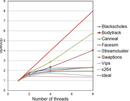
1.2 Speed-up for N=1, 2, 4, 8 Threads on PARSEC Workloads . . . 2
1.3 Control Flow of POSIX API Call . . . 3
1.4 Lock Address is Present in Private L1 Cache of the Processor . . . . 4
1.5 Lock address is Present in Shared L2 Cache . . . 5
1.6 Lock Address is Not Present in L1 or L2 Cache . . . 6
1.7 Locked Cache Line is Present in Private L1 Cache of Another Processor 7 1.8 Distribution of LL Execution Time . . . 8
1.9 LL When Lock is Held and SC Fail . . . 9
2.1 Chip Multi-Processor . . . 12
2.2 MOESI Cache Coherence Transition . . . 14
2.3 Implementation of Lock Using LL-SC Instruction.[7] . . . 15
2.4 Sharing Pattern of Locks Based on Next Acquirer . . . 18
2.5 Histogram of Sharing Pattern . . . 19
4.1 Predictor Table . . . 29
4.2 Base Directory Controller Based Locking . . . 33
4.3 Implicit Queue on Lock Bit . . . 34
4.4 Lock Prediction Mechanism . . . 36
5.1 Overall Speed-up With Lock Prediction Mechanism . . . 38
1. INTRODUCTION
The theoretical or ideal speed-up that can be achieved in a multi-processor system is defined by Amdahl’s law, which states that the sequential portion of the code limits the speed-up of a parallel program. The limitation can be quantified as follows:For a program running on N processors, ifP is the fraction of the program that can be parallelized, the overall speed-up in given by
Speedup= 1/((1−P) + (P/N)) (1.1) For a given P less than 1, as N grows to infinity, the maximum speed-up that can be achieved approaches 1/(1−P). Thus, it can be seen that the limiting factor for speed-up is the serial portion of the program. This is illustrated graphically for large N in Figure 1.1.
Figure 1.1: Speed-up Vs P for Large N
As can be seen from the graph, for large N, in order to achieve a 10x speedup, 90% of the target program needs to be parallelizable. In other words, this is the maximum attainable speed-up in the theoretical case without all the synchronization
and communication overheads.
A characterization of the PARSEC benchmark suite in Figure 1.2 below shows that the speed-up does not scale linearly as the number of processors increase. This is due to the synchronization overhead present in multi-processors.
Figure 1.2: Speed-up for N=1, 2, 4, 8 Threads on PARSEC Workloads In a multi-threaded environment, a portion of the program can be executed in parallel by all the threads at the same time. Some portion of the program needs to be executed by all the threads sequentially. This is referred to as a”critical section”. A critical section is a piece of code that can be executed by only one thread at any given point in time. Synchronization primitives are used to achieve mutual exclu-sion while executing a critical section. Based on the application, various kinds of synchronization primitives can be used. These include mutexes, barriers and condi-tional variables. In C/C++ based programs, pthreads are commonly used to ensure mutual exclusion. The POSIX library provides an API for implementation of
var-ious synchronization primitives. It uses ’load-linked and store-conditional (LL-SC)’ or ’compare-and swap’ (cmpxchg) atomic primitive at the assembly level. A typical control flow of POSIX API call can be depicted as in Figure 1.3
Figure 1.3: Control Flow of POSIX API Call
Various schemes have been proposed to reduce the time spent in acquiring ex-clusive access to a lock in order to execute the critical section and also optimize the time spent by other threads to check if the lock has been released. In order to better understand the overhead of locking mechanism, that is, the process of acquiring and releasing a lock, various examples are provided below.
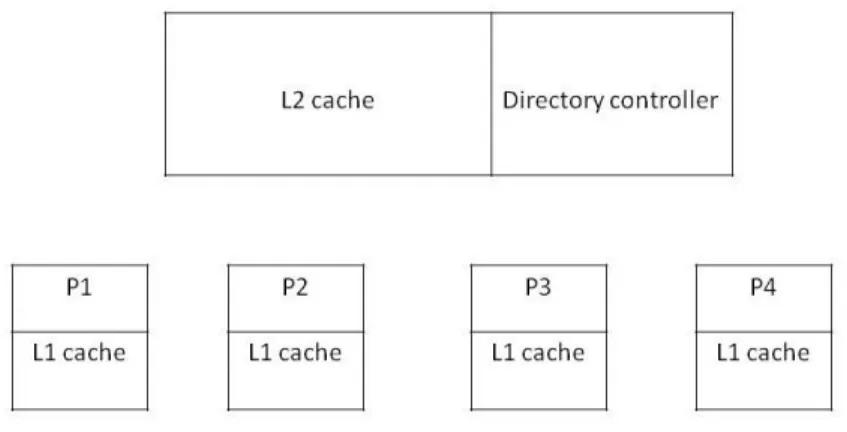
In the examples below, there are 4 processors namely, P1, P2, P3, P4. Each processor has its own private L1 cache. Each cache line maintains a state of the data such as Exclusive (E), Modified (M), Shared (S). Exclusive state means that the data is present only in this cache and no other processor has a copy of the data and data is consistent with the memory. Modified state indicates that the data is present only in this cache and no other processor has a copy of the data but the data
is different from the data in memory. Shared state indicates that the data is present in other caches too and data is consistent with the memory. In the example below, 0x8000 is the lock address, and each processor tries to obtain exclusive access to this lock address. L2 cache is shared between processors. The coherency amongst various processors is maintained using the directory controller.
In the first case as shown in Figure 1.4, processor P1 tries to execute the critical section by trying to obtain the lock address 0x8000. This address is present in the private L1 cache of processor P1 in exclusive state. Hence, no additional clock cycles are consumed in acquiring the lock. This is the ideal case and there is no overhead in acquiring the lock.
Processors
0x8000
E
0x7936
M
0x7968
E
0x7904
S
0x7904
S
0x7904
S
0x7872
E
P1
P2
P3
P4
L1 cache of each processor
Figure 1.4: Lock Address is Present in Private L1 Cache of the Processor
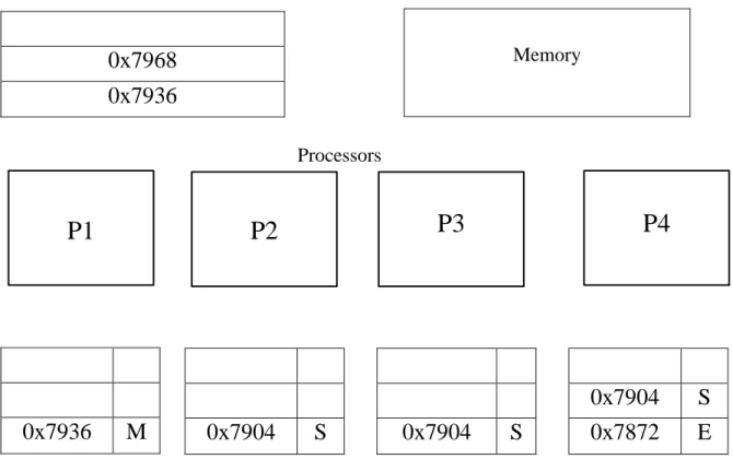
In the second case as show in Figure 1.5, the lock address, 0x8000 is present in shared L2 cache. The control flow of Figure 1.5 is as follows: The locked cache line is not present in private cache of any of the processors and is present only in shared
L2 cache. Hence, the data is sent from L2 cache to L1 cache in exclusive state for further operations. In this case, the overhead of acquiring is the lock is the sum of clock cycles needed to send request to the shared L2 cache and L2 cache responding to the request by sending the lock address in exclusive state.
L2 cache
0x8000
0x7968
0x7936
0x7936
M
0x7968
E
0x7904
S
0x7904
S
0x7904
S
0x7872
E
P1
P2
P3
P4
L1 cache of each processor Processors
Figure 1.5: Lock address is Present in Shared L2 Cache
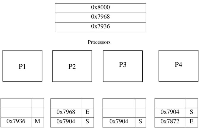
In the third case as shown in Figure 1.6, the lock address, 0x8000 is not present in L1 or L2 cache. The control flow is as follows: Initially, the data is searched in L1 cache. The data is not present in L1 cache and hence a request is sent to L2 cache. The data is also not present in L2 cache. At this point, L2 sends a request to directory to fetch the data. Once the directory receives the data from memory, it
notifies L2 which subsequently sends the data to L1 in exclusive state. In this case, majority of the time is spent in acquiring the lock from the memory.
L2 cache
0x7968
0x7936
Memory
0x7936
M
0x7904
S
0x7904
S
0x7904
S
0x7872
E
P1
P2
P3
P4
L1 cache of each processor Processors
Figure 1.6: Lock Address is Not Present in L1 or L2 Cache
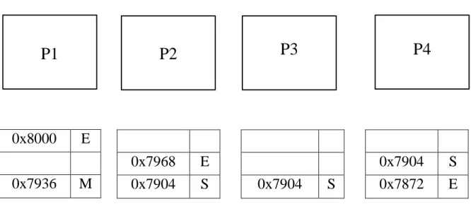
In the fourth case as shown in Figure 1.7, the lock address is present in private L1 cache of another processor (P2). The control flow of Figure 1.7 is as follows: the locked cache line is held in modified state by P2. L2 cache line state indicates that a local exclusive copy of data exists. L2 cache forwards the request to the local owner (in this case, P2 ) and local owner invalidates its copy of cached line and the locked cache line is provided in exclusive state to requestor. In this case, the overhead of
acquiring the lock is the request being forwarded from L2 to L1 cache and the L1 cache releasing the access to the lock. This could have been avoided had the local owner preemptively invalidated its copy of cached line. The goal of this thesis is to reduce the number of cycles taken to acquire a lock.
L2 cache
0x8000
0x7968
0x7936
0x7936
M
0x8000
M
0x7904
S
0x7904
S
0x7904
S
0x7872
E
P1
P2
P3
P4
L1 cache of each processor Processors
Figure 1.7: Locked Cache Line is Present in Private L1 Cache of Another Processor We performed a study on the PARSEC benchmark suite [3] by observing the number of unique lock addresses present in each benchmark. We also compared the time taken by load locked instructions to acquire the lock. They fell into four buck-ets namely, lock present in L1 cache (Figure 1.4), lock address present in L2 cache
(Figure 1.5), lock address present in L1 cache of another processor (Figure 1.7) and lock address present in memory (Figure 1.6). This data as shown in Figure 1.8 was used in understanding the benefit of lock prediction scheme.
Figure 1.8: Distribution of LL Execution Time
Even though, the number of LL instructions that had a miss in L1 cache (and was present in L1 cache of another processor) is less, the number of cycles it takes to fetch data from L1 cache of another processor is more than the former case.In this thesis, we focus on fetching the data from private L1 cache of each processor.
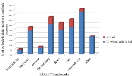
Next, we present a distribution of try lock (executing LL when lock is held) and failed store conditional instructions in PARSEC benchmarks in Figure 1.9.
Figure 1.9: LL When Lock is Held and SC Fail 1.1 Thesis Statement
This thesis proposes an adaptive hardware lock predictor to minimize the latency in acquiring a lock. The predictor stores the most recent lock addresses and the subsequent thread that might acquire this lock. Thus, the goal of this thesis to establish evidence that lock prediction is effective in parallel programs and can be used for data pre-fetch of critical section.
1.2 Thesis Contributions
In this thesis, we propose a lock predictor that aims at improving the performance of multi-threaded applications. So far, most of the work on locking mechanism have focused on optimizing the performance by delaying the release of lock or avoiding the use of locks for critical sections. The area that has not been explored include predictability of lock acquiring sequence, that is, the ability to identify which thread will acquire a lock.
1.3 Thesis Organization
The rest of the thesis is organized as follows: Chapter 2 provides the motivation for this thesis work, Chapter 3 presents the prior work performed in this area, Chapter 4 presents the architecture and detailed description of the components that make up the lock prediction scheme, Chapter 5 discusses the implementation methodology and Chapter 6 provides conclusion and future work.
2. BACKGROUND AND MOTIVATION
This chapter provides the background and motivation behind the proposed ap-proach.
2.1 Background
This chapter presents an overview of chip multi-processor, cache hierarchies, cache coherence and instruction set architecture support for locking mechanism.
2.1.1 Modern Chip Multi-Processor Architecture
In earlier days, performance improvement in processor design was achieved by increasing the frequency of the chip but this has been limited by the memory wall
and power wall. The memory access time has not decreased in correspondence to processor compute time and this difference has led to memory wall. The increase in frequency comes at the cost of rise in power consumption and heat dissipation and this limitation is referred to as power wall. In recent days, the number of parallel applications and also the need to run many applications concurrently have increased. This provides an opportunity to exploit thread level parallelism. Multiple processors running at the same time can use thread level parallelism to achieve the performance speed-up. With the shrinking process technology, we have been able to design Chip multi-processors (CMP) [17] without much increase in area. One variant of CMP is the shared memory multi-processor. In this model, the memory system is distributed physically, that is, it is present at various locations to provide faster access to data. The memory access time is further improved by using cache. Caching is a technique in which a copy of the data in main memory is present in a smaller sized memory unit so that data can be searched and fetched quickly. Since, we create copies of data, it
is important to maintain coherence between the various copies so that we maintain memory consistency. The mechanism used for this is called cache coherence.
A typical layout of a CMP is shown below in Figure 2.1:
Figure 2.1: Chip Multi-Processor
2.1.2 Cache Hierarchies
The L1 cache is the first memory system that is searched to look-up for data when the processor needs to execute an instruction. The L1 cache maintains the state of each of its cache line using cache coherency described in the section below. When the data is not present in the L1 cache, a look-up is performed in the next level of cache called the L2 cache. L1 cache can communicate only with the L2 cache present in the same chip. Size of L1 cache is smaller than the size of L2 cache. The L2 cache is the second fastest memory module in cache hierarchy. If data is present in L2 cache, it sends the data to the corresponding L1 cache. If the data is not present in L2 cache, it sends a request to the memory to fetch the data.
2.1.3 Cache Coherence
Each processor in the chip consists of a private L1 cache and each chip contains one shared L2 cache. The same copy of data can exist in multiple caches. When data is updated in one cache, the older copies of the data in other caches need to be invalidated/updated. This process is called cache coherence. There are various protocols available to implement cache coherence, namely, MSI, MOSI, MESI and MOESI. In the next subsection, we describe the working of MOESI cache coherence protocol.
1. MOESI cache coherence protocol
The MOESI protocol [2] has five states as shown in Figure 2.2 to denote the status of data in each cache line. The formal definitions of the transition states are as follows:
Modified - The data is present in only one cache and it does not match the data in the main memory.
Owner - The data is present in more than one cache and it does not match the data in the main memory. Owner flag indicates that it has exclusive rights for updating the cache line data and reading of this cache line data by other caches does not require any change in the status flag.
Exclusive - The data is present in only one cache and it matches the data in the main memory.
Shared - The data is present in more than one cache and it matches the data in the main memory.
Invalid - The data is obsolete and does not match the data in the main memory. When a new data is fetched from the main memory, it is flagged as exclusive. When the data is updated, the status is changed to modified. When a modified
cache line is read by another cache, the status is changed to owner and the data is shared amongst other caches.
The advantage of MOESI protocol is that the number of times the memory is being accessed to read data is reduced. The flags also clearly indicate whether the data matches the data in the main memory or not.
Figure 2.2: MOESI Cache Coherence Transition
2. Directory Controller
In a bus based architecture, snoopy cache coherence protocol, mentioned as above is typically used. Since this technique uses the broadcasting mechanism for communication, it does not scale well. The other type of cache coherence that is in use is directory based cache coherence.
Directory-based protocols [5, 6, 8, 1] use point-to-point communication and hence this is widely used in CMP. It does not use the broadcast technique and
used to maintain coherence between the various chips on the die. The directory tracks the status of modified data present in various processors. It marks the processor that modified the data as the owner of the cache line. The main benefit of using a directory controller is that it sends a message only to the processor that requires the data or whose data needs to be invalidated. This mechanism can scale well as the number of processors increase.
2.1.4 Instruction Set Architecture (ISA) Support for Locks
In a parallel program, some sections of the code are performed on shared data. In such cases, access to the shared data is serialized. Each processor must obtain exclusive access to the data in order to safely operate on it. The processor performs a comparison of the value in locked address with zero to ensure that the lock is avail-able. In order to avoid a race condition, the processor obtains exclusive access via the cache coherence. The processor then reads the value in the locked address. A value of 0 indicates the lock is available. A value of 1 indicates the lock is unavailable. Once the processor has ensured that the lock is available, a store conditional instruction is used to set the locked address value to 1, marking the lock as unavailable to other threads. This ensures that only one thread can execute the critical section at any given point of time. Above sequence of reading the lock address and obtaining the lock can be implemented using LL-SC instruction.
Try:: LL R2, (R1) / -- read lock ORI R3, R2, 1 BEQ R3, R2, try SC R3, (R1) /-- acquire lock BEQ R3,0,try /*--critical section---*/ SW R2, (R1) /-- release lock
Figure 2.3 illustrates how a lock can be implemented using a LL-SC instruction pair. The LL-SC instruction works as follows: two threads may load the value of 0 to a register but only one will succeed in updating the memory location to a value of 1. The other thread will not be able to update the lock address since an intervening store has occurred. If a thread reads a lock address that is already held by another lock, it keeps reading the lock variable until it is available. This constitutes the first branch in the above code. The second branch resolves races when two processes read the lock variable as available simultaneously. In an Alpha architecture [9] based multi-processor system, each processor has a lock flag. Whenever one of the processors succeed in executing the SC instruction ahead of others, the cache coherency mechanism updates the lock flags of the remaining processors and ensures the mutual exclusiveness of shared memory.
In the x86 architecture, the reading and setting of the lock variable is atomic. The lock/unlock mechanism is implemented using Compare-and-Swap instruction (cmpxchg). It works as follows:
1. The lock address is acquired by comparing the existing value with the expected value.
2. If they are equal, the lock is set to 1.
3. If they are not equal, the existing value is returned.
In this way, the value at the memory location is returned for both the scenarios (lock acquired by one thread and lock not acquired by the other thread) and each thread obtains knowledge of its ability to acquire the lock.
Finally, after the execution of the critical section the lock is released by writing 0 to the lock address. At this point, another thread can enter the critical section and
2.2 Motivation
We perform an analysis of dynamic instruction trace of multi-threaded bench-marks such as PARSEC [3]. Based on the analysis, it was observed that the locks were acquired amongst the threads in a more repetitive pattern or a lock was biased towards a particular thread or there was no predictable pattern in the lock acqui-sition. The repetitive pattern of lock acquisition motivated the design of hardware lock predictor.
The sequence in which the locks were acquired by various processors in PARSEC benchmarks are shown below. Here 1 refers to Processor 1 and 2 refers to Processor 2 and so on. 1. 1, 2, 1, 2, 1, 2 2. 1, 2, 3, 4, 1, 2, 3, 4 3. 1, 2, 1, 1, 1 4. 1, 2, 1, 2, 1, 4 5. 2, 2, 2, 2, 2, 2, 2
The pattern observed in #1 and #2 is the ideal pattern for a lock predictor. In the first case, if thread 1 and thread 2 forwards the lock without any request, time taken to acquire lock will be greatly reduced. The pattern observed in #3 and #4 will lead to unnecessary hand-offs. In the third case, lock is shared but biased towards one thread. In the fourth case, lock is biased towards one thread but many other threads also acquire the lock once. In the fifth case, lock is not shared at all
The graph below in Figure 2.4 shows the percentage of locks that were shared amongst various threads in a predictable (case 1 and 2) and unpredictable manner
(case 3 and 4).
Figure 2.4: Sharing Pattern of Locks Based on Next Acquirer
As can be seen from Figure 2.4, more than 50% of locks are shared between threads in most of the benchmarks. This data shows that a lock predictor can be used to reduce the time taken to acquire a lock.
The sharing pattern can be predictable or unpredictable. The histogram in Figure 2.5 below shows the distribution of locks that were shared in a predictable pattern, locks shared in an unpredictable pattern and locks not being shared at all for a given benchmark. In the last case, the lock is biased towards one thread.
0% 20% 40% 60% 80% 100% 120% Lock shar ing as % PARSEC Benchmarks locks not shared locks shared in unpredicatble pattern locks shared in predictable pattern
3. PRIOR WORK
Before elaborating on the proposed technique, this section attempts to provide an overview of the various techniques that have been proposed to improve the per-formance of synchronization primitives.
3.1 Implementations of Locking Mechanisms
In this section, we describe the various implementations of locks in software and hardware. The widely used techniques for implementing locks in software without the overhead of spinlock include ticket locks [12] and queue-based MCS locks [11]. In directory-based shared multi processors, implementing locking mechanism requires minimal hardware modification.
3.1.1 Ticket Locks
A ticket-based locking system is implemented using two variables, namely, the turn variable and ticket value. Each processor selects a unique ticket value to enter the critical section. The ticket value chosen by a given processor at any given time is higher than the ticket value of all other processes which hold the ticket. The process of acquiring a ticket value is atomic to avoid race conditions. The ticket value is compared with the turn to identify which process can enter the critical section. The turn value is copied to local cache by each process and the read/compare is performed. Hence, when the turn value changes, all the copies need to be invalidated and this significantly increases the number of invalidations performed. This locking mechanism works well only under low contention since it can obtain exclusive access to turn variable.
3.1.2 MCS Locks
A queue based locking system such as MCS lock is implemented using a software distributed queue instead of a global counter. Each node in the queue has a next pointer which is updated when a new process requests for a lock. If there are no other processes waiting to acquire the lock, the next pointer is marked as null. Hence, to acquire a lock, a process has to request for the lock and update the queue. The queue structure adds additional overhead during periods of low contention. The key features of MCS lock include FIFO ordering, spinning on local lock variable and scalability. FIFO ordering is ensured by the presence of instructions such as ’compare-and-swap’. Since it spins on local variables, it works on both coherent and non-coherent caches.
3.1.3 Centralized Hardware Locking Mechanism
One of the simplest implementations of hardware locking mechanism involves maintaining a lock bit vector for each one of the cache lines in the directory con-troller. Whenever a lock is requested for a particular cache line, the lock is granted immediately if no other process holds the lock. If a lock is held by any other pro-cess, the bit vector is updated with the request. Once a process releases the lock, a random process from the bit vector is chosen as the next acquirer and correspond-ing message is sent to that particular process. The disadvantage of this technique includes starvation and lack of FIFO ordering.
3.1.4 Distributed Hardware Locking Mechanism
The distributed hardware locking mechanism is similar to MCS locks (uses dis-tributed queuing model). When a process tries to acquire a lock, it sends a lock request message to the directory controller. If the lock is available, the request is
granted immediately else the tail pointer of the queue is updated with the new re-quest and the rere-quest is also forwarded to the process holding the lock . Once a process releases a lock, it forwards it to the next requestor if it had received the message. By this method, the number of communications to the directory controller is reduced and this results in reduced network traffic.
Since the centralized locking mechanism works well during periods of low con-tention and distributed mechanism during periods of high concon-tention, an adaptive locking mechanism was designed. In this scheme, as long as the number of processes requesting lock is less than four, centralized scheme is used. Once lock contention begins, a distributed locking scheme is used and when a process next pointer is not updated during release of a lock, it implies the system is under low contention and system switches back to centralized scheme. The overall performance of all of the schemes was comparable and hence based on the available hardware, corresponding design can be chosen.
3.1.5 Hardware Locking for System-On-Chip
A hardware based locking mechanism was proposed for System-on-chip architec-ture [15]. In this technique, an additional hardware unit has been added to store the lock addresses. This unit also includes decoder and control logic. Each entry in the lock address indicates whether a lock has been held or not. It also indicates the requestors for the lock. This technique avoids the usage of LL-SC to implement locking mechanisms. Hence, the technique can be ported across architectures. To acquire a lock, the process sends a lock request and the hardware unit checks if the lock bit of the address is not set. If so, the lock is automatically granted. If the lock bit is set for that particular address, the request is updated in the unit. Thus, it avoids the use of LL-SC and there is no need to store a value of 1 in the location
to indicate unavailability of a lock. This step has basically bee taken care of by the hardware unit
During release of a lock, the hardware unit wakes up the next process on line using an interrupt. A FIFO/priority encoder is used to select the process from the lock request queue.
The disadvantage of the technique includes the presence of an additional hardware unit and the use of interrupt to wake up a process from sleep. Even though, the process state need not be saved during interrupt (the execution starts from the instruction before lock), it is still an expensive process.
3.1.6 Fair Reader-Writer Locking Mechanism
In fair reader-writer locking mechanism [16], each lock request is associated with its thread id. By this mechanism, locking will work efficiently even during thread migration. Each core has a lock control unit (LCU). Each memory controller has a Lock Reservation Table (LRT). The LRT maintains a lock queue. Two new instruc-tions called acquire and release need to be added to the instruction set architecture for this scheme. The return values of these instructions are true or false. The argu-ments of the instruction include address to the lock, thread id, read or write mode. If a lock is un-contended, it will be removed from the lock queue. Each lock entry associated with a thread is placed in LCU. Each core communicates with its LCU to acquire and release lock. Based on the address obtained from LCU, the request is sent to LRT. LRT maintains the list of lock requests and updates the queue on new request. To avoid starvation, if a lock is not acquired within a given time frame, lock is released.
Besides the above two techniques, various other hardware locking mechanisms have been proposed. Even though the hardware locking mechanisms outperform the
software locking mechanism, time take to acquire and release the lock, all of them require additional hardware support and modification of ISA for implementation. Hence, in a few cases the disadvantages outweigh the performance.
3.2 Implementations of Lock Speculation Techniques
In this section, we look at various techniques that have been proposed to speculate synchronization.
3.2.1 Implicit Queue On Lock Bit
In implicit queue on lock bit (QOLB) [14], throughput of synchronization is improved by the insertion of delays. The key advantage of the technique is the lack of additional software support needed and using the existing ISA. To perform efficient synchronization, it speculates the program access patterns and delays coherency actions. Initially, a process acquires an exclusive access to a cache line, to perform critical section execution. While executing the critical section, other processes may read the lock variable and hence the cache line state changes from exclusive to shared. Hence, when this process releases the lock, it has to again obtain exclusive access to the lock. In this technique, during LL operation, an exclusive copy of cache line is obtained, assuming this will be followed by SC operation. After this, any subsequent request to that cache line is delayed for a short period of time assuming SC will be successful. If the SC operation does not occur within a finite period of time, the cache line requests are serviced. A priority technique is used to differentiate normal loads from LL operation. If it is a LL operation, the length of the delay mentioned above can be longer. The goal is to wait till the lock is released by a process and then serve subsequent requests to the cache line. This is referred to as delayed response scheme. It is designed for bus based architecture. Since it is based on LL-SC, it is not clear whether the same technique will work for compare and swap instruction.
3.2.2 Speculative Lock Elision
In speculative lock elision [13], critical sections are executed without the use of a lock. For example, to update a hash table, locks are not required. Thus, a processor needs to identify an operation as lock to avoid unnecessary loads and stores. During lock operation, a store operation is performed. This is followed by another store to release the lock. Since, both the stores are performed on the same location, processor can identify this sequence and predict it as a lock operation. In this technique, we predict that memory operations in critical sections will occur atomically and elide lock acquire. The critical sections are executed speculatively and results are buffered. If the above sequence was not performed atomically, a mis-speculation is triggered and a roll back is performed and portion of code is re-executed with lock. This technique is currently implemented in processors designed by Intel.
The key features of the design include lack of: instruction set architecture changes, compiler support, cache coherence changes. Since the Speculative Lock Elision scheme automatically detects and removes unnecessary instances of synchronization, performance is not degraded by the presence of synchronization. As it is a micro-architectural change, it can be incorporated into any system without depending on coherence protocols or system design issues.
3.2.3 Lock Prediction
So far, most of the work on locking mechanisms have focused on optimizing the performance by delaying the response to a lock address once a lock is held or avoiding the use of locks for critical sections. The other aspects that will enable enhanced performance of locks include predictability of locks, that is, the ability to identify which thread will acquire a lock and also the type of synchronization that a thread might acquire [10].
If we are able to predict the next thread that will acquire a lock, which may turn out to be current thread, it will eliminate the use of synchronization primitive. Lock prediction will also enable efficient scheduling by the OS, allowing it to prioritize this thread. Similarly, the cache line for the lock can be prefetched and this will reduce the number of cache misses.
The lock prediction can be performed based on first-to-acquire, last-to-acquire, frequent-acquirer and frequent transition. The first-to-acquire scheme works well for programs in which a lock is local to a single thread. The last-to-acquire also works on the same principle. the most-frequent acquirer works by monitoring the number of times each thread has acquired a given lock and predict the next lock acquirer as the frequent one. Since this technique looks into the entire history of locks, it is more robust to temporary deviations as compared to other schemes. The frequent-transition scheme uses the frequency of lock handoff for prediction. For each lock, a weighted graph containing nodes (threads) and edges (handoff) was maintained. The weight of edge is calculated based on the frequency of handoff. For each thread, the next acquirer is predicted as the edge containing maximum weight. The frequent-acquirer technique outperformed other schemes. This technique does involve storage overhead but since the amount of information stored is small (thread id), in most cases, it does not become a significant overhead. This technique can be further modified to add bias towards a particular type of predictor. This scheme can be modified to add aliasing. In aliasing, instead of assigning unique lock names, the locks are re-used. By re-suing locks, the time spent on cold-start can be significantly reduced. Aliasing can also be added to thread. Thus, the paper compared the accuracy of various prediction scheme that can be used to predict a lock sequence in a program and improve performance.
various predictors and accuracy was calculated. Hence, this technique is a study of PARSEC benchmarks and not an adaptive technique.
So far, we have discussed the various hardware and software locking mechanisms. We have also examined the various schemes to improve the performance of synchro-nization through speculation and insertion of delays. While most of the work on performance improvement has focused on speculating the execution of critical sec-tion, limited work has been conducted on predicting the sequence of lock acquisition and execute the critical section correspondingly. The previous section focused on the accuracy of prediction based on analysis of trace and not the actual implementation of prediction using these schemes. This research will focus on extending the con-cept of lock prediction by implementing an adaptive predictor into lock acquisition sequence.
4. DESIGN AND IMPLEMENTATION
This chapter presents the design of our proposed lock predictor. It provides detailed description of the building blocks of the design.
4.1 Overview of Lock Predictor Design
When a processor needs to execute a critical section, it sends a lock request to the memory. The request is initially sent to the private L1 cache of the processor. If the data is present in L1, it responds to the request by sending the data. If the data is not present in L1, the request is forwarded to L2 cache. The L2 cache receives request for data from L1 cache. The state of L2 indicates if it is present in present in L1 cache of any one of the processors on the same chip or not. Based on the outcome, L2 will send a message to the corresponding processor and obtain the data or send a request to the directory controller. L1 cache of another processor can also receive request for data from L2. In this case, the processor holding the lock forwards the data to L1 requestor. The goal of the thesis is to perform optimization such that the lock address is present in the L1 cache of the requesting processor for majority of the time.
In our design, we predict the next acquirer of a given lock address based on history of the lock address. Instead of forwarding the lock after a request is made, the processor holding the lock, performs a look-up on the predictor table to find the next acquirer of the lock and forwards the lock address without any request after it has completed the execution of critical section by releasing the lock. By this method, the subsequent processor can find the lock address in its own L1 cache and this reduces the time taken to acquire a lock.
• Predictor Table: Each processor maintains a prediction table. The prediction table is a map of the lock addresses and thread id of the subsequent acquirer. It records the lock address and the subsequent requestor during the dynamic execution of instructions. This table is updated every time a mis-prediction of next acquirer of lock address is made. This is the new block that has been added to the existing design.
Figure 4.1: Predictor Table
4.2 Implementation of Lock Predictor Design
In this section, we describe the implementation/working details of the various building blocks of lock predictor.
For our design, we use MOESI cache coherency protocol with a directory con-troller. Each processor has it own L1 cache. L1 cache can communicate only with the L2 cache present in the same chip. The L2 cache is shared among processors on the same chip. If data is present in L2 cache, it sends the data to the corresponding
L1 cache. If the data is not present in L2 cache, it sends a request to the directory controller.
We perform a comparison of the basic directory controller scheme, implicit queue on lock bit scheme and our lock prediction. Each one of the schemes is described below:
In basic directory controller based scheme, L2 receives response from L1 that was holding the lock. L2 cache subsequently forwards the lock to requestor. As can be seen from this implementation, the number of messages exchanged and latency associated is higher in this case.
In Implicit queue on lock bit, on receiving a forward request, by referring to the lock queue, the L1 cache that was holding the lock forwards the request directly to the requestor bypassing the controller. This reduces the number of messages exchanged. In our lock prediction scheme, by performing a look-up of the predictor table, L1 that was holding the lock forwards the request directly to the requestor.
• Directory Controller:When directory controller receives a request to obtain
the data in exclusive state, it performs a look-up. If the data is present in a processor, it sends a forwarding request to the owner. The owner transfers the block to the requestor and the state of directory controller is updated corre-spondingly. If the data is not present in any one of the caches (indicated by the state), a memory fetch request is initiated. On receiving a writeback request, data is written to memory and acknowledgement is sent to the corresponding processor. For Direct Memory Aceess (DMA) requests, invalidations are sent to the processors that contains the data.
The aim of this thesis is to minimize the misses in both L1 and L2 and avoid reference to the memory for lock address.
• Lock Predictor Table Implementation: Whenever the L1 cache receives a lock request, the lock prediction table entry is created. Initially the next requestor is marked as NULL. When the controller sends a request to the cache, to forward the cache line to subsequent requestor, the predictor table is updated with the next acquirer for this lock address. Initial study has shown that the number of unique lock addresses are limited. Hence, we maintain a optimal size of 8 entries in the prediction table. This size was sufficient for performing a look-up in the table.
In order to identify that the load request was a load locked request, following scheme is used. In ALPHA architecture, LD and ST instructions maintain a 16 bit decode field. One of the bits (HW LDST LOCK) indicate if it is a LL/SC instruction. When the processor receives a request, it checks if the bit field is set and instruction is load instruction. If this is the case, the instruction is identified as load locked instruction. In ALPHA architecture, each processor maintains a lock flag and lock address register. These values are updated as true and the corresponding address respectively when a instruction is decoded as locked instruction. When one processor sets the flag, it sends a message to other processors and their flag is invalidated. By this mechanism, we ensure that only one processor is holding the lock, the remaining processors cannot acquire the lock. When the processor sends request to the memory, this information is passed along with the request for data. Thus, we can identify if the request was a locked address request and update the table correspondingly.
The lock prediction works as follows: initially the table is empty. Each proces-sor creates its own unique entry when a load locked request is received. When the controller forwards a L1 request, the predictor table is updated. When a
subsequent locked request is encountered, a look-up of the table is performed. If there is a match, the processor on releasing the lock, auto-invalidates its cached copy and sends an exclusive copy of the locked address to the subse-quent requestor. Thus, we do not wait for the controller to forward the request and we try to maximize the number of times, a locked address is available in the cache.
• Prediction Mechanism: The prediction mechanism is based on recording
the past history of the lock handoff sequence. The prediction accuracy is based on the repetitive patterns of lock handoff from one thread to the other. Since the number of unique addresses recorded is not very large (based on initial limit study), this mechanism works efficiently. This technique is adaptive, in the sense, if a lock is biased towards a particular thread, the map will have the next acquirer marked asNULL. The downside to this method is mis-prediction. An implementation of this method shows that the overhead of mis-prediction outweighs the number of clock cycles saved through prediction.
4.3 Working Example
In a base directory controller based locking method, each processor communicates to the directory controller for lock request and release. The figures ( 4.2, 4.3, 4.4) described below shows the transactions between three processors and the directory controller with respect to a cache line containing lock variable. The arrows represent the requests and the responses between the processors and the directory controller. Numbers on each arrow represent the order of action. Each arrow is enumerated and described below.
Figure 4.2: Base Directory Controller Based Locking
1. Processor P1 sends a lock request to the directory controller. The lock is not being held by any other processor.
2. So, the controller grants the lock.
3. Subsequently, P2 tries to enter the same critical section.
4. The directory controller sends a message to P1 and when P1 has released the lock, its copy of locked cache line is invalidated.
5. At this point, P2 is provided exclusive access. 6. P2 releases the lock.
7. P3 requests lock access.
8. Since no other process holds the lock, the request is granted immediately. 9. P3 releases the lock
In this technique every processor has to communicate to the home node for ac-quiring and releasing a lock. The overhead of the design includes communication with the directory controller for every operation.
A related technique called Implicit Queue on Lock Bit as shown in Figure 4.3 has been used for comparison in this thesisI.It maintains a queue of lock requestors in hardware.
Figure 4.3: Implicit Queue on Lock Bit
1. Processor P1 sends a request for a lock.
2. Since no other processor is holding the lock, the lock is granted immediately. 3. Processor P2 sends the request for same lock address and this is added to lock
queue.
5. P1 releases the lock.
6. P1 forwards the lock to P2.
7. While P2 is holding the lock, P3 places a request for same lock address. 8. Directory controller forwards the request to P2.
9. P2 releases the lock.
10. P2 forwards the lock to P3.
11. P3 on executing the critical section, releases the lock.
This technique improves performance by reducing network traffic, however the requestor must still ask for the cache line directly before it is forwarded.
In the above techniques, the processor which initially acquires the lock, will hold exclusive status until further request. As was seen from the motivation study, this does cost a few cycles when a subsequent thread needs to enter the critical section. The goal of this thesis is to explore if this scenario can be altered and made beneficial to the lock/unlock process as shown in Figure 4.4.
1. P1 initially acquires the lock, it adds the lock address to the map and marks the subsequent acquirer as ’none’
2. P1 is granted access.
3. P1 releases the lock and performs a look-up of the lock address in the prediction table.
4. If the lock address is found, P1 forwards the lock to the next thread without any request from the controller.
5. When P2 needs the lock, the lock address is already present in its L1 cache 6. P2 releases the locks and performs a similar look-up and forwards the lock to
P3
7. P3 obtains exclusive access to lock. 8. P3 requests lock access.
9. P3 does not forward the lock since there is no next acquirer for that lock address in the prediction table.
Figure 4.4: Lock Prediction Mechanism
By this prediction method, we will be able to reduce the time taken to acquire a lock.
5. EVALUATION
In this chapter, we elaborate on the simulation methodology used to implement the design mentioned in the previous chapter. We evaluate the effectiveness of lock predictor by comparing it with two schemes, namely, base scheme and Implicit Queue on Lock Bit.
5.1 Methodology
All experiments were performed using the gem5 [4] full system simulator. The use of a functional simulator has the same effect as if a cycle-accurate model were used with a perfect cache, branch predictor, TLB, pipeline (1-issue, order), in-terconnect, and coherence. The purpose of using a simple functional simulator was to determine the lower bound. Assuming perfect communication across the cache hierarchy and interconnect, program performance is bounded by the serial code re-gions, OS interaction, and synchronization overheads. Synchronization overheads are based upon the ordering imposed by the benchmark algorithm as well as costs incurred within the pthreads library. Each processor has a 2-way set associative 256 KB L1 private cache. The system also has 2MB of shared L2 cache.
We run 8 benchmarks of the PARSEC benchmark suite [3]. The PARSEC suite presents a good model of the multi-threaded workload that is present in the real time environment. The results presented are for the parallel portion of the work load.
The simulator was modified to incorporate the lock prediction structure to the existing design. The simulation was run in the detailed (out-of-order) mode for this workload.
5.2 Results and Analysis
5.2.1 Impact on Performance
We present three cases, baseline, Solando et all’s delayed lock scheme [14] and our proposed lock prediction scheme.
Next, we compared the base case with lock prediction scheme. We observed speed-up in the overall execution of the program. The following graph provides the corresponding results.
Figure 5.1: Overall Speed-up With Lock Prediction Mechanism
In the figure, we see that the lock prediction scheme generally provides a ben-efit of 9% versus baseline. In nearly all cases, it outperforms the delay scheme. Bodytrack and Canneal use synchronization primitives less than 1% of the execu-tion time. Hence, the lock predicexecu-tion scheme did not provide any improvement for
these two benchmarks. X264 had patterns that involved unnecessary hand-off. This resulted in scenario of unnecessary hand-off outweighing useful forwarding. In all other benchmarks, the lock access patterns were a combination of useful forwarding and unnecessary hand-offs.
The following example elaborates the situation where unnecessary handoff is per-formed: A given locked address has a lock access pattern as follows 1, 1, 2, 1, 1. In this case, thread 1 forwards the lock to thread 2 during lock release. But, the subse-quent acquirer of that lock is thread 1. Hence, thread 1 performs an invalidation and subsequently acquires the lock in exclusive state. This is referred to as unnecessary hand-off. In typical schemes, the locked address would remain in exclusive/modified state in thread 32 and it would have acquired the lock without any overhead. This is the downside to this design.
Finally, we analyze the amount of useful forwarding that was performed compared to the total number of forwardings that was performed by the predictor. The graph below presents the predictor efficiency
Figure 5.2: Predictor Efficiency
In X264, due to unwanted forwarding, the predictor efficiency was pretty low. In the remaining benchmarks, the predictor efficiency was above 60%.
6. CONCLUSION AND FUTURE WORK
In this thesis, we proposed a new lock prediction scheme to reduce the overhead of synchronization in multi-threaded programs. In this design, we exploit the repetitive pattern in the lock acquisition process and also the bias of lock addresses towards a single thread. Using this scheme, we observed an average speed up of 9% in the overall execution of the program.
This prediction scheme can be further extended to perform prefetch of data in the critical section and thus we can minimize the cache miss during execution of critical section. We can also try to predict the next lock address of thread since similar handoff techniques were observed across lock addresses
This scheme has also focused on ALPHA architecture. A similar prediction scheme can also be implemented for x86 architecture. Since the technique is focusing only on lock access patterns, the design/implementation of predictor would remain the same across architectures. Modification will be required only in identifying a given memory operation as lock acquisition.
REFERENCES
[1] Anant Agarwal, Richard Simoni, John Hennessy, and Mark Horowitz. An eval-uation of directory schemes for cache coherence. 15th Annual International Symposium on Computer Architecture, pages 280–289, 1988.
[2] AMD. Amd64 architecture programmers manual volume 2: System program-ming, edition 3:14. Publication 24593, September 2007.
[3] Christian Bienia, Sanjeev Kumar, and Kai Li. The parsec benchmark suite: Characterization and architectural implications. 17th International Conference On Parallel Applications, Ontario, Canada, October 2008.
[4] Nathan Binkert, Bradford Beckmann, Gabriel Black, Steven K. Reinhardt, Ali Saidi, Arkaparva Basu, Joel Hestness, Derek R. Hower, Tushar Krishna, So-mayeh Sardashti, Rathijit Sen, Korey Sewell, Muhammad Shoaib, Nilay Vaish, Mark D. Hill, and David A. Wood. The gem5 simulator. ACM SIGARCH Computer Architecture News, May 2011.
[5] Lucien M. Censier and Paul Feautrier. A new solution to coherence problems in multicache systems. IEE Transactions on Computers,vol. 27, no.12, pages 1112–1118, December 1978.
[6] Noel Eisley, Li-Shiuan Peh, and Li Shang. In-network cache coherence. 39th Annual IEEE/ACM International Symposium on Microarchitecture, pages 32– 332, 2006.
[7] Chen-Chi Kuo John B. Carter and Ravindra Kuramkote. A comparison of soft-ware and hardsoft-ware synchronization mechanisms for distributed shared memory
multiprocessors. Tech. Rep. UUCS-96-011, University of Utah, Salt Lake City, UT, USA, Sept 1996.
[8] Daniel Lenoski, James Laudon, Kourosh Gharachorloo, Anoop Gupta, and John Hennessy. The directory-based cache coherence protocol fro the dash multipro-cessor. 17th Annual International Symposium on Computer Architecture, pages 148–159, 1990.
[9] Richard L.Sites. Aplha architecture reference manual.Digital Press, Burlington, Massachusetts, 1992.
[10] Brandon Lucia, Joseph Devietti, Tom Bregan, Luis Ceze, and Dan Grossman. Lock prediction. 2nd USENIX worksop on Hot Topics in Parallelism, Berkeley, CA, June 2010.
[11] John M. Mellor-Crummey and Michael L. Scott. Algorithms for scalable syn-chronization on shared-memory multiprocessors. ACM transactions on Com-puter Systems, Feb 1991.
[12] Maged M. Michael and Michael L. Scott. Scalability of atomic primitives on dis-tributed shared memory multiprocessors. Technical Report TR528, University of Rochester, Computer Science Department, July 1994.
[13] Ravi Rajwar and James R. Goodman. Speculative lock elision:enabling highly concurrent multithreaded execution. 34th International Symposium on Microar-chitecture, Dec 2001.
[14] Ravi Rajwar, Alain Kagi, and James R. Goodman. Improving the throughput of synchronization by insertion of delays. Sixth IEEE Symposium on High-Performance Computer Architecture, pages 168–179, Jan 2000.
[15] Bilge E. Saglam and Vincent J. Monney III. System-on-a-chip processor syn-chronization support in hardware. Processor Design Automation and Test, pages 633–639, 2001.
[16] Enrique Vallejo, Ramon Beivide, Adrian Cristal, Tim Harris, Fernandi Vallejo, Osman Unsal, and Mateo Valero. Architectural support for fair reader-writer locking. 43rd MICRO, Atlanta,USA, pages 275–286, Dec 2010.
[17] David Wentzlaff, Patrick Griffin, Henry Hoffman, Liewei Bao, Bruce Edwards, Carl Ramey, Matthew Mattina, Chyi-Chang Miao, John F.Brown III, and Anant Agarwal. On-chip interconnection architecture of the tile processor. Micro IEEE Vol 27 No.5, pages 15–31, September 2007.