Design and Deployment of AMF Configurations in the
Cloud
Pradheba Chakrapani Rangarajan
A Thesis
in
The Department
of
Electrical and Computer Engineering
Presented in Partial Fulfillment of the Requirements
for the Degree of Master of Applied Science (Electrical and Computer
Engineering) at Concordia University
Montreal, Quebec, Canada
April, 2017
CONCORDIA UNIVERSITY
SCHOOL OF GRADUATE STUDIES This is to certify that the thesis prepared
By: Pradheba Chakrapani Rangarajan
Entitled: Design and Deployment of AMF Configurations in the Cloud and submitted in partial fulfillment of the requirements for the degree of
Master of Applied Science (Electrical and Computer Engineering)
complies with the regulations of this University and meets the accepted standards with respect to originality and quality.
Signed by the final examining committee:
________________________________________________ Chair Dr. R. Raut ________________________________________________ External Examiner Dr. R. Glitho ________________________________________________ Internal Examiner Dr. A. Agarwal ________________________________________________ Co-Supervisor Dr. F. Khendek ________________________________________________ Co-Supervisor Dr. M. Toeroe Approved by: ___________________________________ Dr. W.E. Lynch, Chair
Department of Electrical and Computer Engineering
_______________ 2017___ __________________________________
Dr. Amir Asif, Dean,
iii
Abstract
Design and Deployment of AMF Configurations in the Cloud
Pradheba Chakrapani Rangarajan
With the ever growing popularity of cloud computing, the trend of deploying applications in the cloud is increasing more than ever. Cloud offers computing resources that can be provisioned as required and scaled according to the workload demand. This feature attracts service providers to deploy their applications in the cloud. As users continue to rely more on the services provided by these applications, it is essential to keep the applications running with minimal service outage. Service Availability Forum (SA Forum) has defined a framework called Availability Management Framework (AMF) which can be used to manage service availability. AMF is agnostic to the services provided by the applications. However, it manages the service availability of applications by orchestrating the redundant entities through a configuration called AMF configuration. The design of AMF configurations for a physical cluster based on the functional and non-functional requirements, such as minimum level of service availability, has been proposed in the literature. In these solutions, the number of physical hosts required to deploy an application is given as input and the resource utilization is not taken into consideration. However, for deploying applications in the cloud the number of physical hosts is not fixed and should vary depending on the workload. Therefore, the issue of minimizing the number of physical hosts while meeting the requested level of service availability arises. In particular, the service availability depends not only on the entities involved in providing the service but also on the interferences caused by the collocation of entities. To minimize these interferences, the collocated entities can be grouped into fault isolation units such as VMs. This in turn may increase the number of resources required.
iv
In this thesis, an approach to generate AMF configuration for the cloud is proposed. In this approach, a novel method is used to calculate the number of AMF entities that meets the availability and resource utilization requirements. In addition, a method to estimate service availability is proposed. It aims to predict the availability of service by considering the potential factors that affect availability, including the interferences due to collocation. Furthermore, an approach to deploy AMF applications in the cloud is proposed. As a proof of concept, a prototype that demonstrates the generation and deployment of AMF configurations in an OpenStack cloud has been developed. This prototype includes the existing Monitoring and Elasticity Engine, previously developed in the MAGIC project.
Acknowledgements
Foremost, I would like to express my heartfelt thanks to my supervisor Dr. Ferhat Khendek for providing me the opportunity to do academic research under his supervision. His expertise, encouragement and continuous support helped me throughout the learning process of this thesis. I would like to offer my profound gratitude to Dr. Maria Toeroe for her insightful comments, remarks and immense knowledge which steered me in the right direction during all time of the research.
I would like to acknowledge all my MAGIC colleagues for their friendship and assistance. Especially I would like to thank Mehran Khan for helping me during the final stages of this thesis.
I must also thank my family and friends for all their endless love and faithful support. I am especially grateful to my parents who encouraged me in all of my pursuits and inspiring me to follow my dreams.
This work is partially supported by Natural Sciences and Engineering Research Council of Canada (NSERC), Ericsson Research and Concordia University.
Table of Contents
List of Figures ... viii
List of Tables ... ix
List of abbreviations ... x
Introduction ... 1
1.1 HIGH AVAILABILITY AND SERVICE CONTINUITY ... 1
1.2 THESIS MOTIVATIONS ... 2
1.3 THESIS CONTRIBUTIONS ... 4
1.4 THESIS ORGANIZATIONS... 5
Background and Related Work ... 6
2.1SAFMIDDLEWARE ... 6
2.2AVAILABILITY MANAGEMENT FRAMEWORK ... 7
2.2.1 AMF Entities and AMF Entity Types ... 8
2.2.2 Redundancy models ... 9
2.3ENTITY TYPE FILE (ETF) ... 14
2.4CLOUD COMPUTING ... 14
2.4.1 Key characteristics ... 15
2.4.2 Service models ... 16
2.4.3 Deployment models ... 17
2.5OPENSTACK ... 17
2.6MONITORING AND ELASTICITY ENGINE ... 18
2.7RELATED WORK ... 19
AMF Configuration Generation Process for a Cluster ... 22
3.1INTRODUCTION ... 22
3.2ETFPROTOTYPE SELECTION ... 23
3.3AMFTYPE CREATION ... 24
3.4AMFENTITIES CREATION ... 24
3.5DISTRIBUTE AMFENTITIES FOR DEPLOYMENT ... 24
3.6LIMITATIONS ... 25
AMF Configuration Generation, Deployment and Run-time Management in the Cloud ... 26
4.1INTRODUCTION ... 26
4.2AMF CONFIGURATION GENERATION PROCESS FOR THE CLOUD ... 27
4.2.1 Introduction and overall view ... 27
4.2.2AMF Entities Creation step... 30
4.2.3 Distribute AMF entities for deployment ... 73
4.2.4 Repeating the process for all the type stacks ... 73
4.3DEPLOYMENT IN THE CLOUD ... 76
4.3.1 Deployment information file generation ... 76
4.3.2 VM image creation ... 77
vii
4.4MANAGING AMF APPLICATIONS IN THE CLOUD ... 79
4.4.1 Integration with Monitoring architecture and Elasticity Engine ... 79
4.5SUMMARY ... 81
Prototype Tool ... 83
5.1INTRODUCTION ... 83
5.2AMF CONFIGURATION GENERATION MODULE ... 83
5.3DEPLOYMENT MODULES ... 85
5.4ILLUSTRATION WITH AN APPLICATION ... 87
5.5SUMMARY ... 93
Application – Configuration Generation for AMF Managed VNFs ... 94
6.1INTRODUCTION ... 94
6.2BACKGROUND ON NFV ... 94
6.3MAPPING BETWEEN NFV AND AMF DOMAIN ... 95
6.4AMF CONFIGURATION GENERATION PROCESS FOR VNFS ... 96
6.5CONCLUSION ... 97
Conclusion and Future Work ... 98
7.1CONCLUSION ... 98
7.2POTENTIAL FUTURE RESEARCH DIRECTION ... 99
List of Figures
Figure 2-1 Overview of HPI and AIS services [13] ... 7
Figure 2-2 An example of AMF configuration ... 9
Figure 2-3 An example for No-redundancy redundancy model ... 10
Figure 2-4 An example for 2N-redundancy model ... 11
Figure 2-5 An example for N+M redundancy model ... 12
Figure 2-6 An example for N-way redundancy model ... 13
Figure 2-7 An example for N-way active redundancy model ... 13
Figure 2-8 Scheduling in OpenStack [20] ... 18
Figure 2-9 Monitoring Engine and Elasticity Engine architecture integrated with AMF [21] ... 19
Figure 3-1 AMF Configuration Generation Process for a Cluster [9] ... 23
Figure 4-1 AMF configuration generation, deployment and run-time management in the cloud ... 26
Figure 4-2 Modified AMF configuration generation process for the cloud ... 27
Figure 4-3 Part of extended ETF domain model ... 28
Figure 4-4 Infrastructure domain model ... 29
Figure 4-5 Factors influencing number of physical hosts ... 31
Figure 4-6 Number of SIs per VM ... 34
Figure 4-7 (a) Estimated availability is less than requested availability at max(b) Estimated availability is less than requested availability at (min + max)/2 ... 38
Figure 4-8 Impact zone when actual recovery is SU restart ... 40
Figure 4-9 Availability of a SI ... 52
Figure 4-10 Calculating number of SIs per VM ... 71
Figure 4-11 (a) Repeating the process for all the type stacks ... 74
Figure 4-11(b) Repeating the process for all the type stacks ... 75
Figure 4-12 Deployment process in the cloud ... 76
Figure 4-13 Mapping of AMF node group to anti-affinity group in the OpenStack ... 77
Figure 4-14 VM image ... 78
Figure 4-15 Integration of AMF applications with ME and EE ... 79
Figure 5-1 Data flow in the configuration generation module [9] ... 83
Figure 5-2 Extended AMF configuration generation prototype ... 85
Figure 5-3 Providing ETF input ... 87
Figure 5-4 (a) SG template-Pattern based dialog box; (b) SI template pattern based dialog box; (c) CSI template; (d) Providing infrastructure file and CR file ... 88
Figure 5-5 No of SIs per VM determination and VM flavor selection for SR-0 type stack ... 89
Figure 5-6 No of SIs per VM determination for small VM flavor and SR-1 type stack ... 90
Figure 5-7 No of SIs per VM determination for large VM flavor and VM flavor selection for SR-1 type stack ... 90
Figure 5-8 Created VMs and anti-affinity groups in OpenStack cloud ... 91
Figure 5-9 Monitoring GUI showing the deployed AMF applications in the cloud before scaling ... 92
Figure 5-10 Monitoring GUI showing the deployed application in the cloud after scaling ... 93
List of Tables
Table 4-1 Calculation of No of SGs and No of SUs per SG ... 63 Table 4-2 Information about the component types ... 65 Table 4-3 Information about the infrastructure elements ... 65 Table 4-4 Number of SIs per VM with corresponding number of entities and the estimated availability . 72
List of abbreviations
Act cap per CST Active capability of components per CST
Act proportion Proportion of active SUs in a SG
AGM Available guest memory
APM Available physical memory
CF Clean up failure
CFIWD Clean up action failing while attempting to instantiate a component with delay
CFIWOD Clean up action failing while attempting to instantiate a component
without delay
Clt Time required to perform clean up action for a component
CR Configuration requirements
CSS Time required to set HA assignment for a component
ct Component type
EA Estimated availability
ETF Entity type file
GOSM Memory used by guest OS from infrastructure file
HA High availability
HM Memory used by hypervisor from infrastructure file
HOSM Memory used by host OS from infrastructure file
IF Instantiation failure
K Minimum number of redundant entities
Max Maximum number of SIs per VM
Max no of comps per CT Maximum number of components per CT based on the SU type Max no of SIs per act SU Maximum number of active SIs per SU
Max no of SIs per SG Maximum number of SIs per SG
Max no of SIs per std SU Maximum number of standby SIs per SU
Max no of VMs per PH Maximum number of VMs per physical host based on capacity or SIs Memory required per CSI Memory required by one component to provide a CSI
Memory required per CST Memory required by collaborating components to provide all CSIs of a CST
xi
Memory required per SI Memory required by all collaborating components to provide an active SI assignment
Min Minimum number of SIs per VM
Min no of comps Minimum number of components required per component type
determined using [9]
MTTF Mean time to failure
MTTR Mean time to repair
NFV Network function virtualization
NFVI Network function virtualization infrastructure
NFV-MANO Network function virtualization Management and Orchestration
nia Number of instantiation attempts
NIWD Number of instantiation attempts with delay
NIWOD Number of instantiation attempts without delay
No of act SUs Number of active SUs
No of coll comp per CT Number of collocated components per component type in a SU
No of coll SUs Number of collocated SUs in a VM
No of coll VMs Number of collocated VMs in a PH
No of comps per CT Number of components per CT in a SU
No of CSIs per CST Number of CSIs per CST in a SI
No of PHs Number of physical hosts
No of SGs Number of SGs
No of SIs Number of SIs from CR
No of SIs per PH Number of SIs per physical host
No of SIs per SU Number of SIs provided by a SU
No of SIs per VM Number of SIs provided by a SUs hosted in a VM
No of std SUs Number of standby SUs
No of SUs per SG Number of SUs per SG
No of SUs per VM Number of SUs hosted per VM
No of VM grps Number of VM groups
No of VMs Total number of VMs to deploy all SIs
No of VMs per PH Number of VMs per physical host based on the capacity of a physical host
NS Network service
xii
OBF Overbooking factor from the infrastructure provider
PCNS Probability of clean up not successful
PCS Probability of clean up successful
PINS Probability of instantiation not successful without delay
PINSD Probability of instantiation not successful with delay
PH Physical host
RA Requested availability from CR
SA Service Availability
Set of actual rec of CTs A set having actual recovery of components of a SU, determined using [11]
Set of SGs A set having SGs determined for each CT
SOT Switch over time
std cap per CST Standby capability of components per CST
Std proportion Proportion of standby SUs in a SG
SUT Service unit type
TGM Total guest memory
TPM Total physical host’s memory from infrastructure file
VM Virtual machine
VNF Virtualized network function
VNFC Virtualized network function component
1
Chapter 1
Introduction
In this chapter we will briefly introduce high availability and service continuity. We will also explain the motivations behind the thesis, its contributions and finally, its organization.
1.1
High Availability and Service Continuity
Service availability (SA) is defined as the percentage of time a system is ready to provide its service [1]. Highly available systems are those that can achieve at least 99.999% of service availability [1]. High availability (HA) is an essential and critical requirement for computer based systems that are expected to provide the service around the clock.
Cloud computing is a new and popular paradigm where compute, network and storage resources can be rented and managed in an on-demand fashion over internet [2]. Ensuring availability of application services in the cloud is a challenging task [3]. This is because, failures are inevitable regardless of the reliability of the software components or the underlying infrastructure. The impact of these failures could be catastrophic in some cases. For example in 2013, a major service outage occurred in Amazon’s east coast data center had led to a loss of $66,240 per minute [4].
Highly available systems are designed to avoid single point of failure. This is ensured by incorporating proper redundancy mechanisms [1]. Resources such as software, hardware or communication elements are replicated in the system. The basic way of organizing redundancy is
2
to have an active and a standby resource. The active resource provides the service and shares its state with the standby resource. If the active resource fails, the standby resource takes over the service and thus the service remains provided with continuity [1].
1.2
Thesis motivations
The notion of ubiquitous resources is realized with the advent of cloud computing [5]. By leveraging existing technologies like virtualization [6], infrastructure providers offer computing resources as a service in a pay-as-you-go manner. Service providers rent these resources to build SaaS (Software as a Service) applications and offer them as a service to their customers or end users [5]. As opposed to the traditional computing, cloud computing allows service providers to provision resources as needed during initial deployment of application and scale resources according to the needs. As a result, there is a window of opportunity to optimize and efficiently use resources in the cloud [7]. With the aforementioned advantages, the cloud is attracting more and more service providers. As end users rely more on the services provided by these applications, any unplanned service outage could result in loss of revenue for the service providers. To avoid paying penalties to the customers or end users, service providers design the SaaS applications considering both functional and non-functional requirements including availability requirements [9].
The design of highly available applications is a challenging task. Using reliable application components does not guarantee high availability. One has to incorporate proper redundancy mechanisms depending on the type of the application and appropriate recovery mechanisms to minimize the service outage. More importantly, in the event of failure the coordination among the redundant entities is important to ensure service continuity. Traditionally, along with the application logics the availability mechanisms are also included by the application developers.
3
Service Availability Forum (SA Forum) [8] has defined the Availability Management Framework (AMF) [10], a middleware service that abstracts the availability mechanisms (i.e. managing the life cycle of application components, coordinating redundant entities and executing appropriate recovery mechanisms in the event of failure) into the framework [10]. To manage the availability of application services efficiently, AMF requires information about the application components and services in a configuration file called the AMF configuration [10].
Designing an AMF configuration [9] [11] [12] can be generically viewed as building and dimensioning an application that is intended to provide specific service functionalities. Designing AMF configurations for a cluster based on the functional and non-functional requirements has been proposed in the literature [9]. This approach starts with analyzing the functional requirements (i.e. the type of the services the applications are intended to provide) and identifies the software components that can provide the service. Based on the non-functional requirements (such as the requested level of service availability) and the number of physical hosts required to deploy an AMF application (given as input), an AMF configuration is generated [9]. This approach is not suitable for the cloud, because the number of physical hosts required should not be fixed and this can change according to the workload variations. Therefore, designing AMF applications that can be deployed using a minimum number of physical hosts and meets the requested level of service availability remains an open question. This is a challenging task because, to minimize the number of physical hosts, the software components are collocated in the same environment (example a VM). The repeated failure of software components hosted on the same VM indicates the fault in the VM and requires a VM reboot. This recovery action may affect the availability of all the services provided by the VM (called as interference). To reduce this interference, software
4
components can be grouped into fault isolation units with more VMs. This in turn will increase the number of physical hosts.
While deploying AMF applications (using the generated configurations) in the cloud, if the availability constraints (anti-collocation relation) between the entities is not respected, the service availability will be jeopardized. The anti-collocation relation between the software entities and the VMs are defined in the AMF configuration. However, the availability constraints at the physical host level is not defined in the configuration. To ensure service availability, this should also be taken into consideration.
In this thesis we aim to design, deploy and manage AMF applications in the cloud that meets both availability and resource utilization requirements. Using the existing Monitoring architecture [21] and Elasticity Engine [22], workload variations of the deployed applications can be effectively managed at run-time.
1.3
Thesis contributions
The contributions of this thesis are as follows:
1) An availability estimate method that predicts the availability of a service by considering the potential factors that affect the availability including the interferences due to collocations.
2) A method to calculate the number of AMF entities that satisfies both availability and resource utilization goals. From availability perspectives, the goal is to meet the requested availability and from resource utilization perspective, the goal is to deploy the applications using minimum number of physical hosts. This method is based on the aforementioned contribution on availability estimation taken into account interferences.
5
3) A method to deploy the generated configurations in the cloud has been devised. The purpose of this method is to define the anti-collocation constraints at physical host level based on the generated configurations and to deploy the applications in the cloud without jeopardizing availability.
4) A prototype tool that illustrates the generation and deployment of AMF applications in the cloud has been developed. Also, the deployed application is integrated with the existing Monitoring architecture [21] and Elasticity Engine [22].
5) An application for the AMF configuration generation process in the domain of Network Function Virtualization (NFV) [45] has been developed. Using this process, configurations can be generated for AMF managed Virtual Network Functions (VNFs [44]). For this purpose, the appropriate mapping between both fields has been proposed.
1.4
Thesis organizations
Besides the introduction, the thesis is divided into six chapters. Chapter 2 introduces the necessary background on SA Forum’s AMF, cloud computing and also research works related to this thesis. Chapter 3 briefly explains the configuration generation process for a cluster [9] and highlights its limitations. Chapter 4 presents the generation and deployment of AMF configurations for the cloud. Chapter 5 discuss the prototype implementation of the aforementioned contributions and also the integration with the existing Elasticity Engine [22] and Monitoring architecture [21]. Chapter 6 depicts an application of the AMF configuration generation process for VNF [44]. Chapter 7 concludes this thesis and highlights potential future research directions.
6
Chapter 2
Background and Related Work
This chapter introduces SAF middleware specifications [13] and more importantly focuses on the main concepts involved in understanding the AMF [10]. Further, this chapter briefly introduces the general cloud computing concepts including its characteristics, service models and deployment models [14]. Finally, we review the research works related to this thesis.
2.1 SAF Middleware
Traditionally, telecommunication companies developed their own proprietary HA solutions. Applications built using this solution have limited portability and reusability [13]. In order to address this issue, leading telecommunication and computing companies joined together to develop an open standard for SA [13].
SA Forum [8] emerged to support and manage applications to provide highly available services. For this purpose, it defined two standardized interface specifications [13]: a) The Hardware Platform Interface (HPI) [13] and b) The Application Interface Specification (AIS) [13]. One of the main advantages of standardizing interfaces is that the applications can be ported easily and they can be deployed on any middleware that supports this interface [13].
As shown in Figure 2-1, AIS defined a set of services and management frameworks to support the development and management of highly available applications [13]. Among the frameworks, AMF [10] is used to manage the availability of application services. The next
sub-7
section (Section 2.2) focuses on the necessary concepts required to understand the AMF, as this is the main context of the thesis.
Figure 2-1 Overview of HPI and AIS services [13]
2.2 Availability Management Framework
AMF is responsible for managing the availability of the services provided by the applications by coordinating and managing its redundant entities [10]. To manage the availability of services provided by the applications, AMF requires information about the components, services provided by the components, dependencies and their logical groupings. This information is described as a configuration called AMF configuration [10]. At runtime AMF reads the configuration to know about the current state of a system, applicable redundancy mechanism, error detection and error recovery policies [10]. Using this information, AMF dynamically assigns active or standby roles to the service provisioning entities.
8
2.2.1 AMF Entities and AMF Entity Types
In an AMF configuration, there are two main entities such as service provider entities and the service entities [10]. Service provider entities includes components, service units (SUs), service groups (SGs), AMF nodes and AMF applications while service entities includes component service instances (CSIs) and service instances (SIs). The service provider entities and the service entities together called as AMF entities [10].
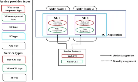
To be able to understand AMF entities and their organization into a hierarchy of logical entities, let us consider an example where a user wants to access a video through a web-interface. The web-server software and the software that plays the video represents the component [10]. It is the smallest service provider entity and also the smallest fault-zone within a system [10]. For the video component to be able to play the video service, workload should be assigned to it. Therefore, CSI represents a unit of service workload that a component is able to provide [10]. One may have noticed that a web-server component and a video player component collaborate to provide the video service. It also implies that due to tight collaboration, fault propagation can also occur [1]. For these reasons, the components that are collaborating to provide a service functionality are grouped logically into SUs [10]. This is the next fault-zone identified by the AMF that can be isolated and repaired on its own [1]. It should also be noted that, respective CSIs assigned to web-server components and video player components will compose a video SI [10]. AMF assigns SIs to SUs during run-time. To protect the service in spite of failures, redundant SUs work together and form a protection group called SG [10]. Typically, an AMF application consists of one or more SGs and also SIs that are protected by the SGs [10]. AMF nodes are logical entities that are used to deploy SGs [10]. This could be mapped to a physical hardware or a virtual machine (VM). SGs are deployed over a group of AMF nodes which forms the AMF cluster [10]. AMF entities are
9
typed, except for nodes and clusters. The common characteristics of AMF entities are captured in their respective types [10]. Figure 2-2 illustrates the AMF configuration for this example with service provider entities, service entities and their corresponding types.
Figure 2-2 An example of AMF configuration
In the event of failure of a component, AMF detects the failure through its health monitoring or error reporting functionalities [10]. Depending on the recovery related attributes specified in the configuration, it then automatically recovers the service by performing recovery action either at the component level (component restart or component failover) or SU level (SU restart or SU failover) or AMF node level (node fail fast or node failover or node switchover) or application level (application restart) or cluster level (cluster reset) [10]. The actual recovery of the components in the context of the configuration can be determined using [11].
2.2.2 Redundancy models
A SG follow one of the following redundancy models; no-redundancy redundancy model; 2N-redundnacy model; N+M redundancy model; N-way active redundancy model; and N-way
AMF Node 1 AMF Node 2
Service Instance Web CSI Video CSI SU 1 Web server component 1 Video Component 1 SU 2 Web server component 2 Video Component 2 SG Application Active assignment Standby assignment Web server component type Video component type SU type SG type App type
Service provider types
Service types
Web CSI type Video CSI type
10
redundancy model; Each SI is characterized with a number of active and standby assignments that varies according to the redundancy model [10].
No-redundancy redundancy model
In this case, each SI has at most one assignment and each SU can take at most one active assignment [10]. In other words, a SU in this redundancy model will not be assigned any standby assignments. Since each SI has only one assignment, from the service perspective this redundancy model provides “no-redundancy” [1]. However, from the service provider perspective there are other SUs in a SG that can take over the service in the case of failure. From this standpoint, this does provides redundancy [10]. Let us consider a SG with two in-service SUs (SU 1 and SU 2) as shown in Figure 2-3. In-service SUs are those that are instantiated and ready to take assignments [10]. This SG is configured to protect one SI (SI 1). For example, at-run time if AMF assigns active role to SU1, then SU2 will be the spare SU.
Figure 2-3 An example for No-redundancy redundancy model
2N redundancy model
It is also called as 1+1 or active-standby redundancy model [10]. From service side, each SI has one active assignment and one standby assignment [10]. From service provider
AMF Node 1 AMF Node 2
SU 1 C1 C2 SU 2 C3 C4 SG Active assignment SI 1 CSI 1 CSI 2
11
perspective, each SG is characterized by at most one active SU, one standby SU and spare SUs depending on the configuration. Let us consider a SG with three SUs (SU1, SU2 and SU 3). This SG is configured to protect 2 SIs (SI 1 and SI 2) as shown in Figure 2-4. For example, at run-time AMF may assign active role to SU 1 and standby role to SU 2 and SU 3 is considered as the spare SU. In the event of failure of SU 1, SU 2 will take over the active role and start providing SI 1 and SI 2. Also, SU 3 will be assigned standby role to protect against failures.
Figure 2-4 An example for 2N-redundancy model
N+M redundancy model
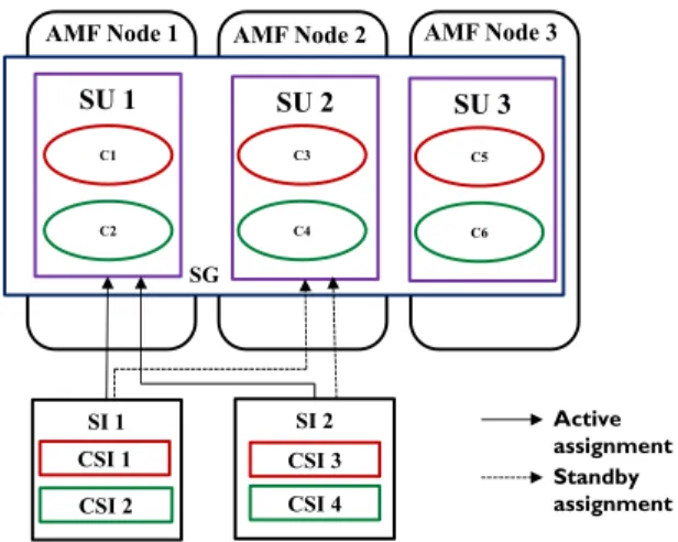
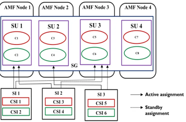
From the service side, each SI has one active assignment and one standby assignment [10] and from the service provider side, a SG is characterized by N active SUs and M standby SUs [10]. Let us consider a SG with four SUs (SU 1, SU 2, SU 3 and SU 4) and this SG is configured to protect 3 SIs (SI 1, SI 2 and SI 3) as shown in Figure 2-5. At run-time, AMF assigns active role to SU 1 and SU 2 (N=2), standby role to SU 3 (M=1) and SU 4 is considered as the spare SU. For example, in the event of failure of SU 1, the active assignment of SI 1 and SI 2 is failed over to SU 3. Also, SU 4 will take the standby role to protect the SIs against failures.
AMF Node 1 AMF Node 2
SI 2 CSI 3 CSI 4 SU 1 C1 C2 SU 2 C3 C4 SG Active assignment Standby assignment SI 1 CSI 1 CSI 2 SU 3 C5 C6 AMF Node 3
12
Figure 2-5 An example for N+M redundancy model
N-way redundancy model
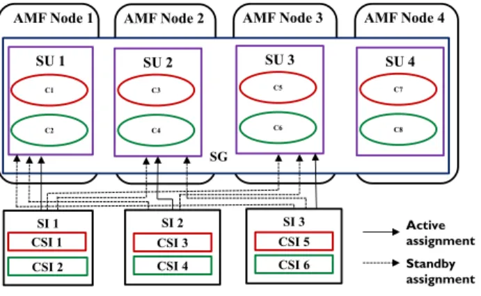
Each SI has one active and one or more standby assignments, depending on the configuration [10]. The SUs in a SG following N-way redundancy model can take active and/or standby role. The only constraint is that, a SU cannot be in the active and standby state for the same SI [10]. Let us consider a SG with four SUs (SU 1, SU 2, SU 3 and SU 4) and this SG is configured to protect 3 SIs (SI 1, SI 2 and SI 3) as shown in Figure 2-6. Also, the number of standby assignments per SI is configured to be 3. At run-time, SU 1 takes active assignment of SI 1 and standby assignments of SI 2 and SI 3. Similarly, SU 2 and SU 3 takes active assignments of SI 2 and SI 3 also standby assignments of other SIs respectively. SU 4 is considered as the spare SU. Note, that the standby assignments are ranked. In the event of failure of SU 3, SU (SU 1 or SU 2) that is assigned the highest ranked standby assignment will provide the SI 3.
AMF Node 1 AMF Node 2
SI 2 CSI 3 CSI 4 SU 1 C1 C2 SU 2 C3 C4 SG Active assignment Standby assignment SI 1 CSI 1 CSI 2 SU 3 C5 C6 AMF Node 3 SU 4 C7 C8 AMF Node 4 SI 3 CSI 5 CSI 6
13
Figure 2-6 An example for N-way redundancy model
N-way active redundancy model
Figure 2-7 An example for N-way active redundancy model
Each SI is characterized by more than one active assignment [10]. This redundancy model does not support any standby assignments [10]. When active assignments are assigned to the SUs of a SG, it implies that all the service functionality is provided by all the active SUs. Let us consider a SG with three SUs (SU 1, SU 2 and SU 3) and this SG is configured to protect 2 SIs (SI 1 and SI 2) as shown in Figure 2-7. Each SI is configured to have two active assignments. At run-time, SU 1 and SU 2 are assigned active roles and SU 3 is considered as a spare SU. In the event of failure of SU 2, AMF will not consider this as a service interruption because, the service is provided by SU 1 [1]. However, AMF will failover the SIs provided by SU 2 to SU 3.
AMF Node 1 AMF Node 2
SI 2 CSI 3 CSI 4 SU 1 C1 C2 SU 2 C3 C4 SG Active assignment Standby assignment SI 1 CSI 1 CSI 2 SU 3 C5 C6 AMF Node 3 SI 3 CSI 5 CSI 6 AMF Node 4 SU 4 C7 C8 AMF Node 3 AMF Node 1 AMF Node 2
SI 2 CSI 3 CSI 4 SU 1 C1 C2 SU 2 C3 C4 SG Active assignment SI 1 CSI 1 CSI 2 SU 3 C5 C6
14
2.3 Entity Type File (ETF)
The software vendors describe the software entities in terms of prototypes in an XML file called ETF [15]. Every prototype mentioned in the ETF possess a name, version and its specific characteristics. For example, each component prototype in ETF specifies the name, version and the type of service the component is intended to provide. In addition, it also includes other characteristics like capabilities of the component prototypes and whether the components of this type can restart or not during service recovery actions [15]. For example, if active and standby capabilities of component prototype are 2 and 4 respectively, then it implies that the component prototype cannot take more than 2 active and 4 standby assignments.
It is mandatory to include the information about component prototypes and component service prototypes; however the information about the other AMF prototypes can be left optional in an ETF [15]. If the information about SU or App prototype is specified, then it implies thata vendor imposes restriction on how the component prototypes can be composed to collaborate.
2.4 Cloud Computing
With the recent advancement in the Internet technology, the need to rapidly deploy applications to meet the growing businesses has increased [5]. To support this growth, often systems are designed to handle maximum workloads. This overprovisioning of resources often results in underutilized server capacity and increases the total ownership cost [7]. Cloud computing reduces the upfront investment in purchasing and maintaining the resources and the total ownership is reduced considerably [5]. Resources can be provisioned as needed on a pay as you basis. This allows the systems to be designed to handle the minimum or average workload and the
15
application servers can be scaled up or down according to the workload demand. National Institute of Standards and Technology (NIST) [14] has proposed the following cloud computing definition:
“Cloud computing is a model for enabling ubiquitous, convenient, on-demand network access to a shared pool of configurable computing resources (e.g., networks, servers, storage, applications, and services) that can be rapidly provisioned and released with minimal management effort or service provider interaction”
Taken further, NIST has also defined five key characteristics, three service models and four deployment models for the cloud [14].
2.4.1 Key characteristics
The following are the important characteristics of a cloud system [14].
On-demand self-service – Without the need for any significant assistance, the cloud resources (compute, storage and network) can be automatically provisioned.
Broad network access – Heterogeneous client platforms such as mobile phones and laptops can be used to access the cloud resources.
Resource pooling – Compute, storage and network resources are pooled by virtualizing them. This allows the flexibility to allocate and manage resources in the cloud computing paradigm.
Rapid elasticity – Resource pooling gives the impression of infinite resources available to the customers. This allows rapidly allocating or reallocating resources to the customers based on their needs.
16
Measured service – The resource pool is shared by multiple customers. Infrastructure provider monitors the resource usages for each customer and bills them according to their usage.
2.4.2 Service models
Infrastructure as a Service (IaaS) - Typically a data center consists of heterogeneous physical servers, switches, storage elements etc. Infrastructure providers own and manage the physical and virtual resources in the data centers. These resources are virtualized and offered as a service to the customers. This allows the flexibility to choose the operating systems and other necessary software required to deploy the applications [5].
Platform as a Service (PaaS) — PaaS provider like Google App Engine offers the necessary built-in services like databases and Application Programming Interface (APIs) to develop applications [16]. This provides the flexibility to develop and deploy applications without having to deal with directly with the infrastructure including network, operating systems or storage [5].
Software as a Service (SaaS) —SaaS providers build SaaS applications (example Microsoft Office 365 [49]) and deploy it over the provider’s infrastructure. Users are allowed to access the application without the need to install, run and maintain the underlying infrastructure, application [49]. Therefore, the up-front cost required to invest in the infrastructure and also in the software licensing is reduced [17].
17
2.4.3 Deployment models
Private cloudA cloud is said to be a private cloud when the services are offered through a private network. Generally it is owed by a single organization that deals with more secure data and requires a more flexible and scalable platform [5].
Public cloud
A cloud is said to be public cloud when the services are offered through the internet (i.e. public network). This allows multiple organizations to share the resources and thereby reducing the total cost. [5]. Examples of public cloud includes, Google’s web based e-mail and file storage system like Dropbox.
Hybrid cloud
A cloud is said to be hybrid cloud when it is a combination of both public and private cloud. The idea is to create a unified model employing both the clouds so that an organization can benefit from the best of both worlds [5].
2.5 OpenStack
OpenStack is a cloud operating system that dynamically manages the compute, network and storage resources in a data center [18]. It provides a cloud computing platform to build public or private cloud. OpenStack contains multiple components. Among these components, compute service is provided by nova [19]. It facilitates the provision of on-demand VM instances using the nova-scheduler service [20]. It is the responsibility of nova-scheduler to determine the mapping of VMs to physical hosts. For this purpose, the nova-scheduler uses the filtering and weighting mechanisms to determine the eligible physical hosts [20]. It allows the use of variety of filters including, but not limited to ram filter, core filter, disk filter, group affinity filter and group
anti-18
affinity filter. With the help of these filters, nova-scheduler eliminates the physical hosts that are not capable of hosting VMs. Further, the nova-scheduler orders the valid list of physical hosts by applying weights to them. Finally, it selects the physical host that is more weighted [20]. Figure 2-8 [20] illustrates the scheduler’s filtering and weighting mechanism. Let us suppose that scheduler applies the ram filter to the list of available hosts (Host 1 to Host 6). It rejects Host 2 and Host 4 due to the presence of inadequate ram resource. It then applies weights to the Host 1, Host 3, Host 5 and Host 6 and ranks Host 5 as the most weighted host. Finally, Host 5 is selected to host a VM instance.
Figure 2-8 Scheduling in OpenStack [20]
2.6 Monitoring and Elasticity Engine
Recently a Monitoring architecture [21] and an Elasticity Engine [22] for AMF managed applications has been proposed in the literature. Unlike the existing monitoring tools in the cloud, this tool monitors the service level workload changes for the AMF managed applications [21]. It then triggers the Elasticity Engine [22] to allocate or reallocate resources based on the workload changes. The Monitoring Engine follows the client-server architecture. Each AMF node in the cluster, runs a monitoring client to measure the service level workload of the components residing on it. The monitoring clients sends the workload to the monitoring server at regular intervals. The monitoring server aggregates the workloads from each component and calculates the associated SI
19
workload [21]. Further, the monitoring server sends the SI workload to the workload analyzer to trigger workload increase or decrease to the Elasticity Engine. For this purpose, workload analyzer checks the received SI workload with the pre-configured threshold value and generate triggers accordingly [21] (Figure 2-9). Elasticity Engine then reads the current configuration and makes the appropriate changes at the SG level or at the cluster level through the Information Model Management (IMM) [23]service. AMF then reacts to the configuration change by adjusting the CSI assignments or SIs in accordance with the modified configuration. Thereby, the service providers are scaled-out or scaled-in based on the service level workload [21].
Figure 2-9Monitoring Engine and Elasticity Engine architecture integrated with AMF [21]
2.7 Related Work
The following works [9] [11] [12] target the generation of AMF configurations. The author in [11] automated the AMF configuration generation process and generates multiple AMF configurations by taking into account various possible configuration options. The author in [12] takes into account the functional requirements and generates AMF configurations using a model driven approach [12]. Both the works [11] and [12] did not consider non-functional requirements such as availability requirements while generating AMF configurations. The author in [9] aims at generating configurations for a cluster that meets functional requirements and non-functional
Instrumented Components Monitoring Client Aggregation Module Monitoring Server Workload Analyzer AMF IMM Elasticity Engine Dispatched callback(s) to assign/(re)assign CSI(s) Component Workload/ CSI assignments SI Workload SI-Workload Change
Read IM/Configuration Change
20
availability requirements (i.e. requested level of service availability). More details on the AMF configuration generation process for a cluster [9] and its limitations are explained in Chapter 3. There are numerous works that discuss about deploying applications in the cloud. Most of them focus on optimizing the placement of VMs on physical hosts based on multiple constraints like resource based, performance and availability [24] [25] [26] [27].The authors in [24] aim at improving the availability and performance of services in the IaaS cloud while placing VMs on physical hosts. For this purpose, a structural constraint-aware VM placement technique is proposed. This is a hierarchical placement approach that considers demand, communication and availability constraints while mapping VMs to physical hosts. Another attempt [25] proposes a highly available optimal placement by considering interdependencies between the application components, communication delay tolerance and resource utilization. The authors in [27] proposed a VM placement method that generates a minimum redundant VM configuration that can survive any k-physical host failures. The above mentioned works considered mapping an application to a VM and optimally placing VMs on physical hosts. In our approach, this application could be mapped to an AMF component.
The authors in [28] presents a request aware VM placement approach to improve the availability of services by choosing the right deployment choices. This work is closely related because it not only considers the mapping application components to one or multiple VMs but also it considers the potential interference that may occur due to multi-tenancy of application components in a VM. However, this solution did not take the specificities of high availability middleware like AMF in to account.
Recently deploying applications in multi-cloud environments is becoming popular [29] [30]. For example the authors in [30] proposes a multi-objective scheduling technique that aims to
21
achieve high availability of applications and also it aims to minimize the application cost (i.e. by optimally scheduling or rescheduling the application components to a node based on the workload demand) and maximize the resource usage. In addition to this, scalability of applications across different clouds is considered.
22
Chapter 3
AMF Configuration Generation Process for a
Cluster
3.1 Introduction
AMF configuration generation process for a cluster [9] requires two inputs; a) ETF model and b) configuration requirements (CR) as shown in Figure 3-1. As mentioned in Chapter 2, ETF is a software catalogue that is used to build AMF applications [15]. An ETF model may include ETFs from different software vendors [9]. CR captures the type of the service the application is intended to provide, the number of SIs of a service type, the number of CSIs of a component service type in each SI, optionally the redundancy model of a SG type, the number of active assignments (for way active redundancy model) and the number of standby assignments (for N-way redundancy model). Deployment details such as the number of AMF nodes in a cluster, cluster startup time, time required by an AMF node to shutdown is also included. In addition, maximum number of attempts required by the AMF to instantiate a component, maximum number of attempts required by the AMF to instantiate a component with a delay between the instantiation attempts and the delay between the instantiation attempts is specified. Finally, the non-functional requirement such as requested level of service availability is also included in the CR [9]. AMF configuration generation process [9] [11] has four main steps: a) ETF prototype selection; b) AMF type creation; c) AMF entities creation; d) Distribute AMF entities for deployment. The authors in [9] applies four design patterns and two methods to enhance the service availability.
23
3.2 ETF Prototype Selection
In this step, ETFs from different vendors are analyzed and the prototypes that can provide the requested service are selected. It is possible to create hierarchy of prototypes (from app types to component types) called type stack from different prototypes therefore, each type stack may lead to different AMF configurations [9].
ETF prototypes from different software vendors are adjusted to improve the service availability. ETF prototypes specify multiple attributes available to configure the software from an availability perspective. Some of the recovery related attributes are altered to minimize the impact zone using the ETF prototype adjustment design pattern [9]. This step also intends to estimate the level of service availability using the availability estimate method [9] to check if a type stack can provide the requested level of service availability. If it is not met, then that type stack is discarded in the early stage of the configuration generation process [9]. Type stacks that meet the requested level of availability are considered for the next step.
24
3.3 AMF Type Creation
AMF types are software entity types that are defined for the AMF management purposes [15]. These AMF types are created from their corresponding ETF prototypes in the type stacks. However, if the information about SU prototype or SG prototype or App prototype is not found, then they are created in this step [9]. ETF prototypes specify a range of available options and this allows the possibility to create multiple AMF types from the same ETF prototype [9]. Using separation of CSTs design pattern, AMF types are created in such a way that the failure of a component will affect only minimum number of SIs [9]. Also, if the system designer has not requested the redundancy model for SG type(s), then this step determines the appropriate redundancy model for a service type based on the active and/or standby capability of component types [9].
3.4 AMF Entities Creation
This step aims to create the number of AMF entities from their corresponding AMF types based on the requested level of service availability. For this purpose, availability estimate-based entities creation method [9] is used. Considering the availability requirement and the number of SIs, this method calculates the number of components, the number of SUs and SGs required and they are configured. Note that these AMF entities are created according to the number of AMF nodes specified in the CR [9].
3.5 Distribute AMF Entities for Deployment
Once the AMF entities are created, then the next step is to distribute the SUs over the AMF nodes and to set the deployment related attributes [9]. In this step, different deployment options
25
are possible. Using load-balanced distribution design pattern, this step aims to distribute SUs in an even manner for 2N-redundnacy model [9].
3.6 Limitations
The above mentioned AMF configuration generation process for a cluster [9] is not suitable for the cloud because of the following issues.
1) This approach requires the system designer to specify the number of physical hosts (AMF nodes) as an input to generate the AMF configurations. These physical hosts are also considered to have infinite capacity. The issue is that the number of physical hosts specified by the system designer may not be minimum because the system designer may neither be aware of the effect of collocating entities nor be aware of the resource limitations. Furthermore, this number of physical hosts affects the AMF entities creation calculation. 2) The availability estimate method used in the AMF configuration generator [9] considers
only the availability of the components. However, in any system the availability of the underlying infrastructure (both virtual and physical infrastructure) is also an important factor to consider.
3) This solution did not consider the effect of deploying these AMF entities together in a collocated manner. When entities are collocated in the same environment (e.g. VM), the collocated entities may fail and affect the availability of other SIs served by that environment. Note that collocated entities may interfere at the SU, VM and at the host level as well.
26
Chapter 4
AMF Configuration Generation,
Deployment and Run-time Management in
the Cloud
4.1 Introduction
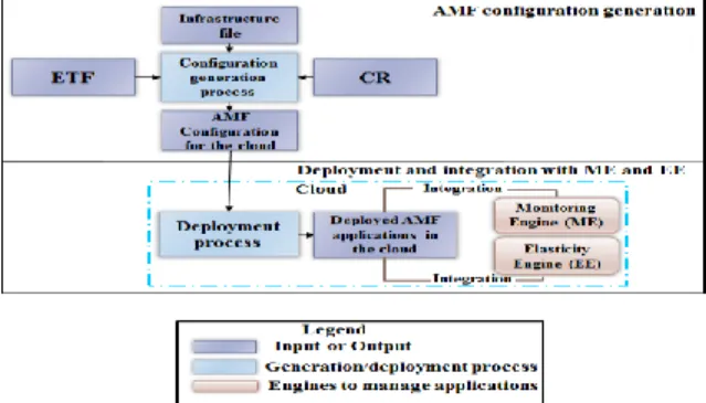
This chapter presents an approach to generate, deploy and manage AMF applications in the cloud. For this purpose, this chapter is divided into three main sections. The first section (Section 4.2) describes the AMF configuration generation process for the cloud. This process overcomes the limitations highlighted in Chapter 3. This section includes the proposed AMF entities creation and availability estimate methods. The second section (Section 4.3) depicts the proposed method to deploy AMF applications in the cloud. The third section (Section 4.4) describes the run-time management of AMF applications using the existing Monitoring architecture [21] and Elasticity Engine [22]. Figure 4-1 illustrates the overall picture of generation, deployment and integration of Monitoring architecture and Elasticity Engine with the deployed applications.
Figure 4-1 AMF configuration generation, deployment and run-time management in the cloud
27
4.2 AMF configuration generation process for the cloud
4.2.1 Introduction and overall view
To design AMF configurations, one has to be aware of the services AMF applications intend to provide. This is abstracted as workload units called SIs and CSIs [10]. The configuration requirements captures the type of the service and the number of SIs and CSIs to be provided by the application with a minimum level of service availability [9]. Our aim while generating AMF configurations is to build applications that can provide the specified number of SIs and guarantee the requested level of service availability. Since these AMF applications are intended to be deployed in the cloud, it is important to use minimum resources (physical hosts). This considerably reduces the upfront investment on infrastructure and by using the existing Elasticity Engine [22], the number of resources can be increased in the future as needed.
Our main goal is to design AMF applications/configurations that can:
provide and protect all the SIs specified number in the CR
meet the requested level of service availability
use minimum resources (physical hosts) for deployment
28
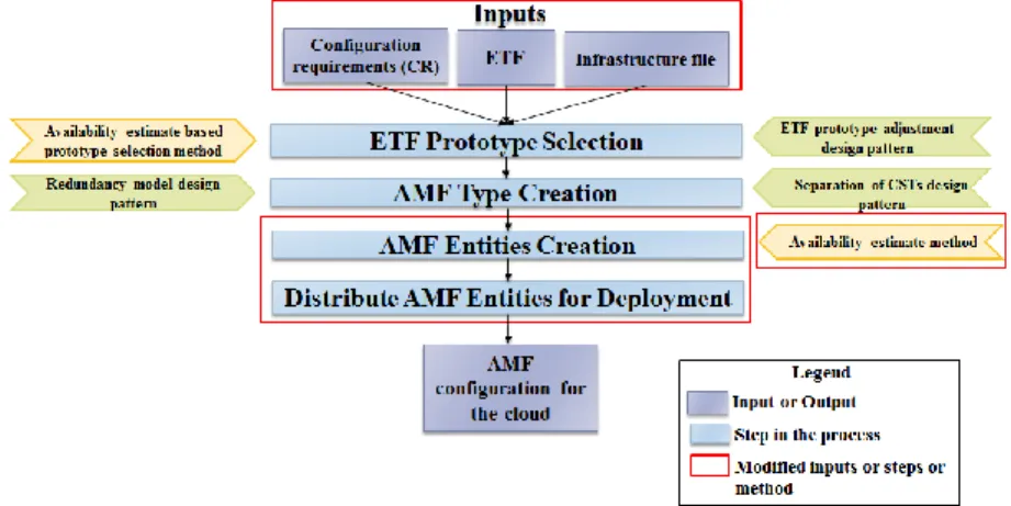
For this purpose, the existing AMF configuration generation process proposed for a cluster environment [9] (explained in Chapter 3) has been revisited and extended. As shown in Figure 4-2, inputs to the generation process, third and fourth steps of the generation process and availability estimate method used at the third step have been modified. The rationale behind the changes are as follows:
1) Inputs
ETF - Software vendor describes the characteristics of components in an ETF file
according to the ETF model defined in [9]. While determining the number of entities, the resource needed for a component to provide a service is required. For this purpose, part of the ETF model is extended as shown in Figure 4-3. Here, CT represents the component type class and CST represents the component service type class. The properties of a component type providing a CST are defined in CTCST association class. The memory usage required by a component to provide a CSI is added to the CTCST association class. Note that for simplicity only the memory resource is considered.
Figure 4-3 Part of extended ETF domain model
CR – According to the CR model defined in [9], the system designer specifies the
deployment information like the number of AMF nodes (i.e. physical hosts) along with the information about SIs (i.e. the number of SIs in a service type, the number of CSIs in each
CT CST CTCST 1..* 1..* componentCapabilityModel: String defaultNumStandbyCsi :Integer maxNumStandbyCsi: Integer defaultNumActiveCsi:Integer maxNumActiveCsi:Integer memoryUsageCsi: Integer
29
SI and the requested level of service availability). As mentioned in Chapter 3, a system designer is not aware of the effect of collocation and resource limitations, therefore the number of physical hosts specified may not be accurate and minimum. For this purpose, the number of physical hosts is no longer specified as input and the CR model is modified accordingly.
Infrastructure file – In addition to the ETF and CR, deployment information such as
capacity of the physical host, the number of available VM flavors, the capacity of VM flavors, Mean Time to Fail (MTTF) of the infrastructure elements like physical hosts, VMs, guest OS, host OS and hypervisors are required while determining the number of entities. For this purpose, a third input called infrastructure file is added in the configuration generation process. This file is created according to the domain model shown in Figure 4-4.
Figure 4-4 Infrastructure domain model
2) Modifications to the third and fourth steps – It is important to mention the reason behind changing only the third and fourth step as opposed to changing entire steps of the generation process. The first two steps of the generation process is about building the application types (i.e. starting from app types to all the way to component types) that can provide the desired service functionality [9].Note that in these steps the applications are designed at the type level
30
independent of the deployment environment. However, the later steps are deployment specific. The third step of the configuration generation process [9] calculates the number of instances of each AMF entities (components, SUs, SGs) that forms an application according to the number of physical hosts in the physical cluster. In contrast, while designing applications for the cloud, only the minimum number of physical hosts needs to be considered. Therefore, the third and fourth steps are modified and they are explained in detail in Section 4.2.2 and 4.2.3 respectively.
3) Modifications to the availability estimate method – The availability estimate method [9] considers only the availability of components providing a service (SI). Collocating AMF entities into the same environment also affects service availability. This should also be taken into account while estimating the service availability. Also, in any systems the availability of multiple elements like physical infrastructure and virtual infrastructure should also be considered. For the above mentioned reasons, the availability estimate method [9] used in the third step of the generation process is modified.
4.2.2AMF Entities Creation step
4.2.2.1 Factors influencing the number of physical hosts
As shown in Figure 4-5, there are three factors that influence the number of physical hosts:
1) Redundancy; 2) Interferences due to the collocated entities and 3) Capacity of VMs and physical hosts.
31
1) Redundancy
Redundancy requires additional resources to protect the service against failures [1]. The number of SUs per SG determines the minimum number of physical hosts required. This is because, SGs are deployed over VMs in an anti-affinity group and eventually these VMs are hosted over physical hosts. For example, in the case of 2N-redundancy model, a minimum of one active SU and one standby SU is required per SG. These SGs are deployed over a minimum of two VMs and these VMs are hosted in an anti-affinity group over a minimum of two physical hosts. Taking into account potential interferences between the collocated entities and the capacity of the physical host and the VM, the number of physical hosts required may be more than two.
2) Interference between the collocated entities
The rationale behind collocating SUs belonging to different SGs into a VM and collocating VMs protecting different services into a physical host is to minimize the number of physical hosts. However, when several entities are collocated they may fail and affect the other SIs hosted in that environment. To minimize the interference, components can be grouped into multiple fault isolation units such as VMs, but this may increase the number of physical hosts required.
Interference between the collocated entities Physical host 1 Physical host 2
Redundancy Capac it y of the phy si cal hos t and VMs VM 1 VM 2 Anti-affinity VM group 1 SG1 C1 SU1 C2 C3 SU2 C4 VM 3 VM 4 C5 SU3 SG2 C6 C7 SU4 C8 Anti-affinity VM group 2
32
3) Capacity of the resources
Another factor influencing the number of physical hosts is the capacity of the host and the capacity of the VMs hosted on it. Physical hosts have finite resources in terms of RAM, disk, number of cores and so on. VMs are available in various pre-defined flavors such as tiny, medium, large etc. A limited number of VMs, with different flavors, can be hosted on a physical host. It is well known that virtualization introduces some overhead due to the presence of the hypervisor in the host and the guest OS in each of the VMs, and this will be taken into account in the calculation of collocated instances.
4.2.2.2 Two phases of AMF entities creation step
We identified two phases in the AMF entities creation step.
1) Determining the number of SIs per VM flavor from the perspective of availability and resource utilization
2) Selection of the VM flavor
For each type stack, created in the step one and two of the configuration generation process, the above mentioned phases are repeated. The number of SIs per VM calculation is carried out for all the VM flavors in the infrastructure file. Next, in the second phase, an appropriate VM flavor that satisfies availability requirements and supports a minimum number of physical hosts is selected.
1) Determining the number of SIs per VM flavor from the perspective of availability and resource utilization for a type stack
Initially, the memory required by the components collaborating to provide an active SI assignment of the requested service type is calculated. It is the summation of the memory required
33
for all the CSIs of a SI as shown in the Equation (1). Here, Memory required per CST represents the memory required for all the CSIs per CST.
k m
k Memory required per CSTk
per SI required
Memory
1 (1)
k iterates through the m component service types in the service type. Equation (2) determines the
Memory required per CST by multiplying the Memory required per CSI and the No of CSIs per CST. The Memory required per CSI of a CST and the No of CSIs per CST are obtained from the
extended ETF model and the CR respectively.
CST per CSIs of No * CSI per required Memory CST per required Memory (2)
The total guest memory (TGM) of a VM flavor is used by the guest OS and the components hosted by the VM. To determine the guest memory available (AGM) to host the components, the virtual memory required by the guest OS (GOSM) is excluded from the TGM as shown in Equation (3).
GOSM TGM
AGM (3) Next, based on the memory required to provide an active SI assignment and the AGM, the number of SIs per VM (No of SIs per VM) is determined using Equation (4).
per SI required Memory AGM floor VM per SIs of No (4)
Once the No of SIs per VM is calculated, then the next step is to determine the capacity of the SU in terms of SIs and the number of SGs (No of SGs) and evaluate the effect of collocating components in a SU, collocating SUs in a VM and collocating VMs in a physical host. These collocated entities are those that are hosted in the same environment as the components providing
34
the SI, whose availability is being estimated using the availability estimate method in Section C. The failure of these collocated entities would require the recovery action to be performed in a bigger scope and this impacts the availability of the other SIs. For example, if the components in the collocated SUs are configured to recover with component restart fails repeatedly, then in order to capture the fault the recovery action may escalate from component level to the SU and VM levels thereby affecting the availability of other SIs.
Even though the capacity of the VM sets an upper limit for the number of SIs it can host, in reality it is limited due to the interference caused due to the collocated entities, the capacity of the SU and the No of SGs. As shown in Figure 4-6, min represents the minimum number of SI (which is actually one) a VM may provide while max represents the maximum number of SIs a VM can support based on its capacity, the SU capacity and the No of SGs. When the No of SIs per VM (i.e. the components providing these SIs) is increased gradually from min to max, the availability of the services decreases as the interference between the collocated components increases. On the other hand, the collocation of components in the VMs results in lesser number of VMs and physical hosts. Our aim is to determine the actual No of SIs per VM that meets the requested availability and results in minimum number of physical hosts.
![Figure 2-1 Overview of HPI and AIS services [13]](https://thumb-us.123doks.com/thumbv2/123dok_us/10183345.2920822/19.918.142.731.200.555/figure-overview-hpi-ais-services.webp)
![Figure 2-8 Scheduling in OpenStack [20]](https://thumb-us.123doks.com/thumbv2/123dok_us/10183345.2920822/30.918.234.687.443.637/figure-scheduling-in-openstack.webp)
![Figure 2-9 Monitoring Engine and Elasticity Engine architecture integrated with AMF [21]](https://thumb-us.123doks.com/thumbv2/123dok_us/10183345.2920822/31.918.304.574.458.651/figure-monitoring-engine-elasticity-engine-architecture-integrated-amf.webp)
![Figure 3-1 AMF Configuration Generation Process for a Cluster [9]](https://thumb-us.123doks.com/thumbv2/123dok_us/10183345.2920822/35.918.145.706.121.381/figure-amf-configuration-generation-process-cluster.webp)