DigitalCommons@University of Nebraska - Lincoln
Faculty Publications from the Department of
Electrical and Computer Engineering
Electrical & Computer Engineering, Department of
2008
A Scalable Clustered Camera System for Multiple
Object Tracking
Senem Velipasalar
University of Nebraska-Lincoln, [email protected]
Jason Schlessman
Princeton University
Cheng-Yao Chen
Princeton University
Wayne H. Wolf
Georgia Institute of Technology
Jaswinder P. Singh
Princeton University
Follow this and additional works at:
http://digitalcommons.unl.edu/electricalengineeringfacpub
Part of the
Computer Engineering Commons
, and the
Electrical and Computer Engineering
Commons
This Article is brought to you for free and open access by the Electrical & Computer Engineering, Department of at DigitalCommons@University of Nebraska - Lincoln. It has been accepted for inclusion in Faculty Publications from the Department of Electrical and Computer Engineering by an authorized administrator of DigitalCommons@University of Nebraska - Lincoln.
Velipasalar, Senem; Schlessman, Jason; Chen, Cheng-Yao; Wolf, Wayne H.; and Singh, Jaswinder P., "A Scalable Clustered Camera System for Multiple Object Tracking" (2008).Faculty Publications from the Department of Electrical and Computer Engineering. 394. http://digitalcommons.unl.edu/electricalengineeringfacpub/394
Research Article
A Scalable Clustered Camera System for
Multiple Object Tracking
Senem Velipasalar,1Jason Schlessman,2Cheng-Yao Chen,2Wayne H. Wolf,3and Jaswinder P. Singh4 1Electrical Engineering Department, University of Nebraska-Lincoln, Lincoln, NE 68588, USA
2Electrical Engineering Department, Princeton University, Princeton, NJ 08544, USA
3School of Electrical and Computer Engineering, Georgia Institute of Technology, GA 30332, USA 4Computer Science Department, Princeton University, Princeton, NJ 08544, USA
Correspondence should be addressed to Senem Velipasalar,[email protected] Received 1 November 2007; Revised 21 March 2008; Accepted 12 June 2008 Recommended by Andrea Cavallaro
Reliable and efficient tracking of objects by multiple cameras is an important and challenging problem, which finds wide-ranging application areas. Most existing systems assume that data from multiple cameras is processed on a single processing unit or by a centralized server. However, these approaches are neither scalable nor fault tolerant. We propose multicamera algorithms that operate onpeer-to-peercomputing systems. Peer-to-peer vision systems require codesign of image processing and distributed computing algorithms as well as sophisticated communication protocols, which should be carefully designed and verified to avoid deadlocks and other problems. This paper introduces the scalable clustered camera system, which is apeer-to-peermulticamera system for multiple object tracking. Instead of transferring control of tracking jobs from one camera to another, each camera in the presented system performs its own tracking, keeping its own trajectories for each target object, which provides fault tolerance. A fast and robust tracking algorithm is proposed to perform tracking on each camera view, while maintaining consistent labeling. In addition, a novel communication protocol is introduced, which can handle the problems caused by communication delays and different processor loads and speeds, and incorporates variable synchronization capabilities, so as to allow flexibility with accuracy tradeoffs. This protocol was exhaustively verified by using theSPINverification tool. The success of the proposed system is demonstrated on different scenarios captured by multiple cameras placed in different setups. Also, simulation and verification results for the protocol are presented.
Copyright © 2008 Senem Velipasalar et al. This is an open access article distributed under the Creative Commons Attribution License, which permits unrestricted use, distribution, and reproduction in any medium, provided the original work is properly cited.
1. INTRODUCTION
This paper takes a holistic view of the problems that need to be solved to build scalable multicamera systems. Scalability has two aspects: computation and communication. In order to address scalability in both of these aspects, we present the scalable clustered camera system (SCCS), which is a
distributed smart camerasystem for multiobject tracking. In a
smart camerasystem, each camera is attached to a computing
component, in this case different CPUs. In other words, in
SCCS, a different processing unit is used to process each
camera, which provides scalability in computation power. Moreover, processing units communicate with each other in a peer-to-peer fashion eliminating the need for a central server, and thus providing scalability on the communication side and also removing a single point of failure.
Reliable and efficient tracking of objects by multiple
cameras is an important and challenging problem, which finds wide-ranging application areas such as video surveil-lance, indexing and compression, gathering statistics from
videos, traffic flow monitoring, and smart rooms. Due to
the inherent limitations of a single visual sensor, such as limited field of view and delays due to panning and tilting, using multiple cameras has become inevitable for object tracking in applications requiring increased coverage of areas. Multiple cameras can enhance the capability of vision applications, providing fault-tolerance and robustness for issues such as target occlusion. Hence, many research groups
have studied multicamera systems [1–30].
Yet, using multiple cameras to track multiple objects poses additional challenges. One of these challenges is
the consistent labeling problem, that is, establishing
cor-respondences between moving objects in different views.
Multicamera systems, rather than treating each camera
individually, compare features and trajectories from different
cameras in order to obtain history of the object movements, and handle the loss of the target objects which may be caused by occlusion or errors in the background subtraction (BGS) algorithms.
Different approaches have been taken to solve the
consistent labeling problem. Kelly et al. [14] assume that
all cameras are fully calibrated. Funiak et al. [31] propose
a distributed calibration algorithm for camera networks.
Chang and Gong [8] and Utsumi et al. [25] employ
fea-ture matching. Yet, relying on feafea-ture matching can cause
problems as the features can be seen differently by different
cameras due to lighting variations. In addition, calibrating cameras fully is expensive and impractical to install by the end user, since it requires some expert intervention.
Kettnaker and Zabih [15] use observation intervals and
transition times of objects across cameras for tracking.
Lee et al. [18] assume that the intrinsic camera parameters
are known and use the centroids of the tracked objects to estimate a homography and to align the scene ground plane
across multiple views. Khan and Shah [16] present a method
that usesfield of view(FOV) lines and does not require the
cameras to be calibrated. However, due to the way the lines are recovered, they may not be localized reliably, and if there
is dense traffic around the FOV line, the method can result
in inconsistent labels. More recently, Calderara et al. [6,7]
and Hu et al. [12] presented methods for consistent labeling
making use of the principle axes of people.
Cai and Aggarwal [5] present a system in which only
the neighboring cameras are calibrated to their relative coordinates. Targets are tracked using a single camera view until the system predicts that the active camera will no longer have a good view of the object. The tracking algorithm then
switches to another camera. Nguyen et al. [22] introduce a
system in which all cameras are calibrated, and the most appropriate camera is chosen to track each object. The tracking job is assigned to the camera that is closest to
the object. However, with a handoffor switching approach,
even though increased coverage is provided, and objects can be tracked for longer periods of time, the tracking is still being performed on one camera view at a time. This is not a fault-tolerant approach, since the camera responsible for tracking can break down, and detecting and recovering from this, if recovery is possible, can introduce some delay. In addition, the camera assigned for the tracking of an object may not have the view of the object we are interested in. For instance, the camera closest to a person may be viewing that person from the back while the interest is seeing that person’s face. Moreover, occlusions, merging/splitting of objects, foreground blobs that are detected incompletely may cause frequent switching of cameras.
In order to provide fault-tolerance, robustness, and mul-tiple views of the tracked targets, objects in the overlapping regions of the fields of view of cameras should be tracked simultaneously on those views with consistent labels. This way, even if a camera breaks down, other cameras can still
continue tracking and trajectories of the same object from different views can be obtained. Also, in the case of occlusion or loss of target objects, data about the object features and
trajectories in different camera views can be exchanged to
keep the trajectories updated in all camera views.
As cameras become less expensive, many systems will use large numbers of cameras for better coverage and higher
accuracy. Thus, scalability and computational efficiency of
multicamera systems are very important issues that need to be addressed. The performance and scalability of such systems should not be debilitated with additional cameras. Although many groups have developed methods to combine data from multiple cameras, much less attention has been
paid to the computational efficiency and scalability. Many
existing systems assume that multiple cameras are processed on a single CPU or by a centralized server. However, these are not scalable approaches, and they introduce a single point
of failure. Chang and Gong [8] propose a system that is
implemented on an SGI workstation with two cameras. For a single CPU system, the amount of processing necessary to track multiple objects on multiple views can be excessive for real-time performance. Moreover, scalability is debilitated as each additional camera imposes greater performance requirements.
In order to increase processing power, and handle
mul-tiple video streams,distributed systemshave been employed
instead of using a single CPU. In a distributed system,
different CPUs are used to process inputs from diff
er-ent cameras. Yet, most existing distributed multicamera systems use a centralized server/control center. Yuan et al.
[30] present a distributed surveillance system in which
computers are connected to a server, and camera units do not collaborate with each other or exchange information.
Collins et al. [9,10] introduced the VSAM system, where all
resulting object hypotheses from all sensors are transmitted at every frame back to a central operator control unit.
Nguyen et al. [20] propose a multicamera system where all
the local processing results are sent to a main controller.
Lo et al. [32] introduce a multisensor distributed system
where a central server coordinates the processing of the
sensor inputs. Krumm et al. [17] present a multicamera
mul-tiperson tracking system for theEasyLivingproject. They use
two sets of color stereo cameras, each connected to its own computer. A program called stereo module locates
people-shaped blobs, and reports the 2D ground plane locations
of these blobs to a tracking program running on a third computer. Using a central server or a control unit for data coordination/integration simplifies some problems, such as video synchronization and communication between the algorithms handling the various cameras. But server-based multicamera systems have a bandwidth scaling problem, since the central server can quickly become overloaded with the aggregate sum of messages/requests from an increased number of nodes. Also, the server is a single point of failure for the whole system. In addition, server-based systems are not practical in many realistic environments, and have high installation costs. Besides the algorithm development, hardware design and resource management have also been
necessitate the use ofpeer-to-peersystems, where individual nodes communicate with each other without going through a centralized server. Several important issues need to be addressed when designing peer-to-peer systems. First, com-munication between processing elements takes a significant amount of time. This necessitates the design of tracking algo-rithms requiring relatively little interprocess communication between the nodes. Decreasing the number of messages between the nodes also requires a careful design and choice of when to trigger the data transfer, what data to send in what fashion, and to whom to send this data. The system must also maintain the consistency of data across nodes as well as operations upon the data without use of a centralized server. Also, even if the cameras and input video sequences are synchronized, communication and processing delays pose a serious problem. Depending on the amount of processing each processor has to do, one processor can run faster/slower than the other. Thus, when a processor receives a request, it may be ahead/behind compared to the requester. These
issues mandate efficient and sophisticated communication
protocols for peer-to-peer systems.
Atsushi et al. [1] use multiple cameras attached to
different PCs connected to a network. They calibrate the
cameras to track objects in world-coordinates, and send
message packets between stations. Ellis [11] also uses a
network of calibrated cameras. Bramberger et al. [3] present
a distributed embedded smart camera system with loosely coupled cameras. They use predefined migration regions to handover the tracking process from one camera to another. But, these methods do not discuss the type and details of communication, and how to address the communication and processing delay issues.
As stated previously, peer-to-peer systems require effi
-cient and sophisticated communication protocols. These protocols find use in real-time systems, which tend to have stringent requirements for proper system functionality. Hence, the protocol design for these systems necessitates transcending typical qualitative analysis using simulation and instead, requires verification. The protocol must be checked to ensure that it does not cause unacceptable issues such as deadlocks and process starvation, and has correctness properties such as the system eventually reaching specified operating states.
Verification of communication protocols is a rich topic, particularly for security and cryptographic systems.
Karlof et al. [34] analyzed the security properties of two
cryptographic protocols. Evans and Schneider [35]
veri-fied time-dependent authentication properties of security
protocols. Vanack`ere [36] modeled cryptographic protocols
as a finite number of processes interacting with a hostile environment, and proposed a protocol analyzer trust for verification. Finally, a burgeoning body of work exists per-taining to the formal verification of networked multimedia
systems. Bowman et al. [37] described multimedia stream as
a timed automata, and verified the satisfaction of quality of
service (QoS) properties including throughput and
end-to-Our previous work [27,28] introduced some of the tools
necessary towards building a peer-to-peer camera system.
The work presented in [28] performs multicamera tracking
and information exchange between cameras. However, it was implemented on a single CPU in a sequential manner, and the tracking algorithm used required more data transfer. This paper presents SCCS together with its communication protocol and its exhaustive verification results. SCCS is a scalable peer-to-peer multicamera system for multiobject
tracking. It is a smart camerasystem wherein each camera
is attached to a computing component, in this case different
CPUs. The peer-to-peer communication protocol is designed so that the number of messages that are sent between the
nodes is decreased, and thesystem synchronization issue is
addressed.
A computationally efficient and robust tracking
algo-rithm is presented to perform tracking on each camera view, while maintaining consistent labeling. Instead of transferring control of tracking jobs from one camera to another, each camera in SCCS performs its own tracking and keeps its own trajectories for each target object, thus providing fault tolerance. Cameras can communicate with each other to resolve partial/complete occlusions, and to maintain consistent labeling. In addition, if the location of an object cannot be determined at some frame reliably due to the errors resulted from BGS, the trajectory of that object is robustly updated from other cameras. SCCS keeps trajectories updated in all views without any need for an estimation of the moving speed and direction, even if the object is totally invisible to that camera. Our tracking algorithm deals with the cases of merging/splitting on a single camera view without sending requests to other nodes in the system. Thus, it provides coarse object localization
with sparse message traffic.
In addition, we introduce a novel communication pro-tocol that coordinates multiple tracking components across the distributed system, and handles the processing and com-munication delay issues. The decisions about when and with whom to communicate are made such that the frequency and size of transmitted messages are kept small. This protocol incorporates variable synchronization capabilities, so as to
allow flexibility with accuracy tradeoffs. Nonblocking sends
and receives are used for message communication, since for each camera it is not possible to predict when and how many messages will be received from other cameras. Moreover, the type of data that is transferred between the nodes can be changed, depending on the application and what is available, and our protocol remains valid and can still be employed. For instance, when full calibration of all the cameras is tolerated,
the 3Dworld coordinates of the objects can be transferred
between the nodes. We exhaustively verified this protocol
with success by using theSPINverification tool.
We introduced the initial version of the SCCS and
its communication protocol in [29, 39]. We extended the
communication protocol to address real-time concerns, and to handle conflicts in received replies. In this paper, we
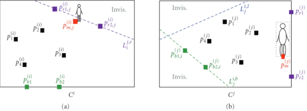
Invis. p(1i) p2(i) p3(i) p(4i) p(bi1) p (i) b2 Ci p(ri1,)j p(ri2,)j p(mi),j Lij,r (a) Invis. Invis. p(1j) p(2j) p(3j) p4(j) p(bj1,)i p(bj2,)i Cj pr(1j) pr(2j) p(mj) Lij,b L1,jl (b) Figure1:p(b1,j)iandp (j)
b2,iare the corresponding locations ofp
(i)
b1andp (i)
b2, respectively, and the recovered FOV line passing throughp (j)
b1,iand
p(bj2,)iis shown with a dashed green line on the view ofCj.
present this protocol and its verification results in detail. We also compare the number of messages that need to be sent around in a server-based scenario and in our system, and present results of this comparison. We show that, contrary to the server-based scenario, the total number of messages sent around by our system is independent of the number of trackers in each camera view. In addition, we compare the server-based system scenario with our peer-to-peer system
in terms of the messageloadson the individual nodes, and
show that the number of messages a single node has to handle is considerably less in our peer-to-peer system. We
present results of different sets of experiments that were
performed to obtain the speed up provided by SCCS, to
measure average data transfer accuracy and averagewaiting
time. Experimental results demonstrate the success of the
proposed peer-to-peer multicamera tracking system, with
a minimum accuracy of 94.2% and 90% for new label
and lost label cases, respectively, with a high frequency of synchronization. We also present the results obtained after exhaustively verifying the presented communication
protocol with different communication scenarios.
The rest of the paper is organized as follows:Section 2
describes the computer vision algorithms in general. More specifically, the recovery of FOV lines, the consistent labeling algorithm, and the tracking algorithm are described in Sections2.1.1,2.2, and2.3, respectively. The communication
protocol is introduced inSection 3, and its verification and
obtained results are described inSection 4.Section 5presents
the experimental results obtained with several different video
sequences with varying difficulty, andSection 6 concludes
the paper.
2. MULTICAMERA MULTIOBJECT TRACKING
2.1. Field of view (FOV) lines
Khan and Shah [16] introduced the FOV lines, and showed
that when FOV lines are recovered, the consistent labeling
problem can be solved successfully. The 3D FOV lines of
camera Ci are denoted by Li,s [16], where s ∈ {r,l,t,b}
correspond to one of the sides of the image plane. The
projections of the 3DFOV lines of cameraCionto the image
plane of cameraCjwill result in 2Dlines denoted byLi,s j, and
called theFOV lines.
2.1.1. Recovery of field of view lines
Khan and Shah [16] recover FOV lines by observing
moving objects in different views and using entry/exit events.
However, since the method relies on object movement in
the environment, there needs to be enough traffic across a
particular FOV line to be able to recover it. In addition, the
output of this method can be affected by the performance of
the BGS algorithm. Depending on the size of the objects, they may not be detected instantly or entirely, and thus, FOV lines may not be located reliably.
Since FOV lines will play an important role in our consistent labeling algorithm and also in our communication protocol later, it is necessary to recover all of them in a robust way. We present robust and reliable methods for recovering FOV lines and for consistent labeling. The method presented for the recovery of FOV lines does not rely on the object movement in the scene or on the performance of BGS algorithms. This way, all visible FOV lines in a camera view
can be recovered at the beginning even if there is no traffic
at the corresponding region. In addition, there is no need to know the intrinsic or extrinsic camera parameters. It is assumed that cameras have overlapping fields of view, and the scene ground is planar. Then a homography is estimated to recover the FOV lines.
The inputs to the proposed system are four pairs of
corresponding points (chosen offline on the ground plane)
on two camera views. These points in the views of Ci
and Cj are denoted by P(i) = {p(i) 1 ,. . .,p
(i)
4 } and P(j) =
{p(1j),. . .,p (j)
4 }, respectively, and are displayed in black in
Figure 1. Let p(ki) = (x (i) k ,y (i) k , 1) T , where k ∈ {1,. . ., 4}, denote the homogeneous coordinates of the input point
pk(i) = (xk(i),y(ki)). Then, a homography (H) is estimated from{p(1i),. . .,p (i) 4 } and{p (j) 1 ,. . .,p (j)
4 } by using the direct
linear transformation algorithm described by Hartley and Zisserman [40].
(a) Setup 1—Camera 1 (b) Setup 1—Camera 2 (c) Setup 2—Camera 1 (d) Setup 2—Camera 2
Figure2: (a)-(b) and (c)-(d) show the recovered FOV lines for two different camera setups. The shaded regions are outside the FOV of the other camera.
(a) (b) (c)
Figure3: (a), (b), and (c) show the recovered FOV lines. The shaded regions are outside the FOV of the other cameras.
The image of the camera view whose FOV lines will be recovered on the other view is called thefield image. After the homography is estimated, the system finds two points on one
of the boundaries of thefield image, so that each of them is
in general position with the four input points. Then it checks with the user that these boundary points are coplanar with the four input points. Let us denote the two points found on
the image boundarysof the cameraCiby p(i)
s1 =(x(s1i),y(s1i))
andp(s2i)=(xs2(i),ys2(i)), wheres∈ {r,l,t,b}correspond to one
of the sides of the image plane (Figure 1). The corresponding
locations of (xs1(i),y(s1i)) and (x(s2i),ys2(i)) on the view of camera Cj are denoted byp(j) s1,i =(x (j) s1,i,y (j) s1,i) andp (j) s2,i =(x (j) s2,i,y (j) s2,i),
and computed by using
Hp(i) sn ∼=p (j) sn,i, (1) wheren ∈ {1, 2},p(sin) =(x (i) sn,y (i) sn, 1) T
, and ps(nj),idenotes the
homogeneous coordinates ofp(snj),i=(x (j) sn,i,y (j) sn,i).x (j) sn,iandy (j) sn,i
are obtained by normalizing p(snj),i, so that its third entry is
equal to 1. Once p(s1j,)i and p
(j)
s2,i are obtained on the other
view, the line going through these points defines the FOV
line corresponding to the image boundarys of the camera
Ci. Two points are found on each boundary of interest and
the FOV line corresponding to that boundary is recovered similarly. Let us illustrate these steps by an example referring to Figure 1. Let the boundary of interest be the bottom boundary of the view ofCi, thus sidesisb. The system finds p(b1i)and p
(i)
b2 on this boundary, which are displayed in green
inFigure 1(a), as described above. Then, the corresponding
locations of these points on the view ofCjare computed by
using (1). These corresponding points are denoted by p(b1j),i
andp(b2j),i, and are displayed in green inFigure 1(b). The line
going throughp(b1j),iandp(b2j),iis the FOV line corresponding to
the bottom boundary of cameraCi. This line is denoted by
Lij,b, and is shown with a dashed green line on the view ofCj
inFigure 1(b).
Figures2to4show the recovered FOV lines for different
video sequences and camera setups. Although there was
no traffic along the right boundary of Figure 2(b), the
corresponding FOV line is successfully recovered as shown inFigure 2(a).
2.1.2. Checking object visibility
As stated previously, Lij,s denotes the projection of the 3D
FOV line Li,s onto the view of Cj and is represented by
the equation of the line, which is written as y = Sx+C.
Henceforth, a point pm(j) =(xm(j),ym(j)) will be considered on
the visible side ofLij,sif sign(y
(j)
m −Sx(mj)−C)=sign(ya(j)− Sxa(j)−C), where (xa(j),y(aj)) are the coordinates of the p(aj)
which is any one of the input points inP(j).
When an objectO(j)enters the view ofCj, BGS is applied
first and a bounding box around the foreground (FG) object
is obtained. Then, its visibility in the view ofCi is checked
by employingLij,s. The midpoint (p
(j)
m ) of the bottom line of
the bounding box of the object is used as its location. If this point lies on the visible side ofLij,s, for alls∈ {r,l,t,b}, then
(a) (b) (c)
Figure4: (a), (b), and (c) show the recovered FOV lines. The shaded regions are outside the FOV of the other cameras.
2.2. Consistent labeling
The consistent labeling scheme of Khan and Shah [16] is
based on the minimum distance between FG objects and a FOV line. However, performing the labeling based only on the FOV lines can be error-prone as more than one object can be in the vicinity of the line especially in crowded scenes, or multiple people can enter one view at the same time. Also, if the entry of an object is detected with a delay due to the errors in BGS, the corresponding object in the other camera will move further away from the line which may cause another object with the wrong label to be closer to the FOV line.
Instead of relying only on the FOV lines, the following steps are employed for more robustness: first, the visibility
of a new object O(j), entering the view of Cj from side
s, by Ci is checked as described in Section 2.1.2. Then,
the corresponding location (pm(i),j) of p
(j)
m in the view of
Ci is calculated by using (1) as depicted in Figure 1. The
foreground objects in the view of Ci, which were on the
invisible side ofLij,sand move in the direction of the visible
side of the line, are determined. From those foreground objects, the one that is closest to the pointp(mi),jis found, and
its label is given to theO(j). Similarly, if multiple people enter the scene simultaneously, the algorithm uses their calculated corresponding locations in the other view to resolve the ambiguity.
2.3. The tracking algorithm: coarse object localization
with sparse message traffic
Our proposed tracking algorithm allows for sparse message
traffic by handling the cases of merging and splitting within
a single camera view without sending request messages to other cameras.
First, FG objects are segmented from the background in each camera view by using the BGS algorithm presented
by Stauffer and Grimson [41], which employs adaptive
background mixture models. Then, connected component analysis is performed, which results in FG blobs. When a new FG blob is detected within the camera view, a new tracker is created, and a mask for the tracker is built where the FG pixels from this blob and background pixels are set to be 1 and 0, respectively. The box surrounding the FG pixels of the
mask is called thebounding box. Then, the color histogram of
the blob is learned from the input image, and is saved as the
model histogramof the tracker.
At each frame, the trackers are matched to detected
FG blobs by using a computationally efficient blob tracker
which uses a matching criteria based on the bounding box intersection and the Bhattacharya coefficientρ(y) [42] defined by
ρ(y)≡ρp(y),q= pz(y)qzdz. (2)
In (2), zis the feature representing the color of the target
model and is assumed to have a density functionqz while
pz(y) represents the color distribution of the candidate FG
blob centered at locationy. The Bhattacharya coefficient is
derived from the sample data by using ρ(y)≡ρp(y),q= m u=1 pu(y)qu, (3) where q = {qu}u=1...m, and p(y) = {pu(y)}u=1...m are
the probabilities estimated from the m-bin histogram of
the model and the candidate blobs, respectively. These probabilities are estimated by using the color information at the nonzero pixel locations of the masks. If the bounding box of an FG blob intersects with that of the current model
mask of the tracker, the Bhattacharya coefficient between the
model histogram of the tracker and the color histogram of the FG blob is calculated by using (3). The tracker is assigned to the FG blob which results in the highest Bhattacharya
coefficient, and the mask, and thus the bounding box, of
the tracker are updated. The Bhattacharya coefficient with
which the tracker is matched to its object is called the
similarity coefficient. If the similarity coefficient is greater than a predefined distribution update threshold, the model histogram of the tracker is updated to be the color histogram of the FG blob to which it is matched.
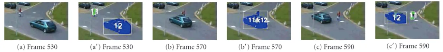
Based on this matching criteria, when objects merge, multiple trackers are matched to one FG blob, and the labels of all matched trackers are displayed on this blob, as shown in Figures5,6,23, and24. The masks of the trackers are then updated in the previously discussed fashion. The trackers that are matched to the same FG blob are put into amerge state, and in this state their model histograms are
(a) Frame 530 (a) Frame 530 (b) Frame 570 (b) Frame 570 (c) Frame 590 (c) Frame 590
Figure5: Example of successfully resolving a merge. (a), (b), (c), (a), (b), and (c) show the original images, and the tracked objects with their labels, respectively.
(a) Frame 795 (b) Frame 815 (c) Frame 877 (d) Frame 920 (e) Frame 950
Figure6: Example of resolving the merging of multiple objects.
are matched to their targets based on the bounding box
intersection and Bhattacharya coefficient criteria mentioned
above.
There may be rare but unfavorable cases where an FG object, appearing after the split of merged objects, may not be matched to its tracker. We deal with these cases as follows:
denote two trackers byT1andT2, and their target objects by
O1andO2, respectively. When these objects merge,O1∪2is
formed, andT1 andT2are both matched toO1∪2. AfterO1
andO2split,BTiOj are calculated, where{i,j} ∈ {1, 2}, and BTiOjdenotes the Bhattacharya coefficient calculated between
the histograms ofTi andOj. Based onBTiOj, both T1 and
T2 can still be matched toO2, for instance, and stay in the
merge state. Denote the similarity coefficient of Ti by STi.
Thus, in this case, ST1 = B12 and ST2 = B22. This can
happen because the model distributions of the trackers are
not updated during themerge state, and there may be changes
in the color ofO1during and after merging. Another reason
may be O1 andO2 having similar colors from the outset.
When this occurs,O1is compared against the trackers which
are in themerge stateand intersect with the bounding box of
O1. That is, it is compared againstT1andT2, andBT1O1and
BT2O1are calculated. Then,O1is assigned to the trackerTi∗,
where
i∗=argmin
i∈{1,2}
STi−BTiO1 . (4)
If a foreground blob cannot be matched to any of the
trackers, and if there are trackers in the merge state, the
unmatched object is compared against those trackers by
using the logic in (4), which is also applicable if there are
more than two trackers in themerge stateas shown in Figures
6and23.
As stated previously, this algorithm provides coarser
object localization and decreases the message traffic by not
sending a request message each time a merging or splitting
occurs.If the exact location of an object in the blob, formed
after the merging, is required, we propose another algorithm
that can be used at the expense of more message traffic:
when a tracker is in the merge state, other nodes that can
see its most recent location can be determined as described inSection 2.1.2, and a request message can be sent to these nodes to retrieve the location of the tracker in themerge state. If the current location of the tracker is not visible by any of
the other cameras, then the mean-shift tracking [42] can be
activated.
The mean-shift tracking is error-prone since it can be distracted by the background. It is also computationally
more expensive. Thus, when a tracker is in themerge state,
it is preferable to send messages to other nodes, and request the location of this tracker, if its most recent location is in their FOV. Thus, this algorithm requires additional message
traffic. We proposed this second algorithm as an alternative
if the exact location of each tracker in the merge state
is required. The experiments presented in Section 5 were
performed by using the first proposed algorithm as the tracking component of the SCCS.
3. INTER-CAMERA COMMUNICATION PROTOCOL
One issue that needs to be addressed when using peer-to-peer systems is that communication is expensive and takes a significant amount of time. Also, the number of messages that are sent between the nodes should be decreased to save power and increase speed. Another issue is maintaining consistency for data across cameras as well as operations upon the data without the use of a centralized server. Even if the cameras and input video sequences are synchronized, communication and processing delays pose a serious
prob-lem. The processors will have different amounts of processing
to do, and may also run at different processing rates. These,
coupled with potential network delays, cause one processor to be ahead of/ behind the others during execution. Thus, when a processor receives a request, it may be ahead/behind
compared to the requester. Hence, system synchronization
becomes very important to ensure the transfer of coherent vision data between cameras. All these issues mandate an
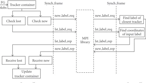
Tracker container
Check lost Check new
Receive lost Receive new
Update tracker container MPI library Find label of closest tracker Find coordinates of input label FG blobs
Synch frame Synch frame
new label req new label req
lst label req
lst label rep
lst label req
lst label rep new label rep new label rep
CameraCi CameraCj
Figure7: Communication between two cameras.
The protocol of SCCS utilizes point-to-point communi-cation, as opposed to some previous approaches that require
a central message processing server. Our approach offers a
latency advantage and removes the single point of failure. Moreover, nodes do not need to send the state of the trackers to a server at every single frame. Thus, contrary to the server-based scenario, the total number of messages sent around by our system is independent of the number of trackers in each camera view. This decreases the number of messages
considerably as will be discussed inSection 3.5. Furthermore,
compared to server-based systems, the proposed protocol decreases the message load on each node. This design is more scalable, since for a central server implementation, the server quickly becomes overloaded with the aggregate sum of messages and requests from an increased number of nodes.
In this section, the protocol of SCCS is presented, which is a novel peer-to-peer communication protocol that can handle communication and processing delays and hence maintain consistent data transfer across multiple cameras. This protocol is designed by determining the answers to the following questions.
(a)When to communicate: determining the events which will require the transfer of data from other cameras.
These events will henceforth be referred to asrequest
events.
(b)With whom to communicate: determining the cameras to which requests should be sent.
(c)What to communicate: choosing the data to be transferred between the cameras.
(d)How to communicate: designing the manner in which the messages are sent, and determining the points during execution at which data transfers should be made.
The protocol is designed so that the number of messages
that are sent between the nodes is decreased, and thesystem
synchronizationissue is addressed.
The block diagram in Figure 7 illustrates the concepts
discussed in this section. It should be noted that, at some point during execution, each camera node can act as the requesting or replying node. The implementation of the proposed system consists of a parallel computing cluster with communication between the nodes performed by the
message passing interface (MPI) library [43]. In this work,
the use of MPI is illustrative but not mandatory since it, like other libraries, provides well-defined communication operations including blocking/nonblocking send and receive, broadcast, and gathering. MPI is also well defined for inter- and intra-group communication and can be used to manage large camera groups. We take advantage of the proven usefulness of this library, and treat it as a transparent interface between the camera nodes.
3.1. When to communicate: request events
A camera will need information from the other cameras when (a) a new object appears in its FOV, or (b) a tracker cannot be matched to its target object. These events are called
request events, and are referred to asnew labelandlost label
events, respectively. If one of these events occurs within a camera’s FOV, the processor processing that camera needs to communicate with the other processors.
In thenew labelcase, when a new object is detected in
the current camera view, it is possible that this object was already being tracked by other cameras. If this is the case,
the camera will issue anew label request to those cameras
to receive the existing label of this object, and to maintain consistent labeling.
CameraCi could also need information from another
node when a tracker inCicannot be matched to its target
object, and this is called thelost labelcase. This may occur,
for instance, if the target object is occluded in the scene or cannot be detected as an FG object at some frame due to the failure of the BGS algorithm. In this case, alost labelrequest
cameras may become necessary is when trackers are merged and the location of each merged object is required. However, if the exact location of the object is not required, and coarser localization is tolerated, then the tracking
algo-rithm introduced in Section 2.3can be used to handle the
merging/splitting within single camera view without sending request messages to the other nodes.
3.2. With whom to communicate
The proposed protocol is designed such that rather than sending requests to every single node in the system, requests are sent to the processors who can provide the answers for them. This is achieved by employing the FOV lines.
When a request needs to be made for an objectO(j)in
the view ofCj, the visibility of this object by cameraCi is
checked using the FOV lines as described inSection 2.1.2.
If it is deduced that the object is visible by Ci, a request
message targeted for nodeiis created and the ID of the target
processor, which isiin this case, is inserted into this message. Similarly, a list of messages for all the cameras that can see this object is created.
3.3. What to communicate
The protocol sends minimal amounts of data between
different nodes. Messages consist of 256-byte packets, with
character command tags, integers, and floats for track labels and coordinates, respectively, and integers for camera ID numbers. Clearly, this is significantly less than the amount of data inherent in transferring streams of video or even image data and features. Considering that integers and floats are 4 bytes, and a character is 1 byte, we currently do not use all of the 256 bytes. As more features are discovered that are useful and important to transfer between cameras, they will be inserted into the message packets. Messages that are sent between the processors are classified into four categories: (1) new label request messages, (2) lost label request messages, (3) new label reply messages, and (4) lost label reply messages.
3.3.1. New label request case
If an FG object viewed by cameraCicannot be matched to
any existing tracker, a new tracker is created for it, all the cameras that can see this object are found by using the FOV lines, and a list of cameras to communicate is formed. A request message is created to be sent to the cameras in this list. The format of this message is
Cmd tag Target id Curr id Side x y Curr label.
(5)
In this case, Cmd tag is a character array that holds
NEW LABEL REQindicating that this is a request message
for thenew label case.Target id andCurr idare integers.
For instance, Curr id is i in this case. These ID numbers
are assigned to the nodes by MPI at the beginning of the
execution. Side is a character array that holds information
about the side of the image from which the object entered the scene. Thus, it can beright, left, top, bottom,ormiddle.
The next two entities, x and y, are floats representing
the coordinates of the location (pm(i)) of the object in the
coordinate system of Ci. Finally, Curr label is an integer
holding the temporary label given to this object byCi. The
importance and benefit of using this temporary label will be clarified in Sections3.4and5.
3.3.2. Lost label request case
For every tracker that cannot find its match in the current frame, the cameras that can see the most recent location of its
object are determined by using FOV lines. Then, alost label
request message is created to be sent to the appropriate nodes to retrieve the updated object location. The format of a
lost labelmessage is
Cmd tag Target id Curr id Lost label x y. (6)
Cmd tagis a character array that holdsLOST LABEL REQ
indicating that this is a request message for the lost label
case.Target idandCurr idare the same as described above.
Lost label is an integer that holds the label of the tracker,
which could not be matched to its target object. Finally, x
andyare floats that are the coordinates of the latest location (p(mi)) of the tracker in the coordinate system ofCi.
3.3.3. New label reply case
If nodejreceives a message, and theCmd tagof this message
holdsNEW LABEL REQ, then node jneeds to send back a
reply message. The format of this message is
Cmd tag Temp label Answer label Min pnt dist.
(7)
In this case, Cmd tag is a string that holdsNEW LABEL
REP indicating that this is a reply message to anew label
request. Temp label and Answer label are integers.
Temp label is the temporary label given to a new object
by the requesting camera, and Answer label is the label
given to the same object by the replying camera. Finally,
Min pnt dist is the distance between the corresponding location of the sent point and the current location of the object.
As stated inSection 3.3.1, theNEW LABEL REQ
mes-sage has information about the requester ID, side, and object
coordinates in the requester coordinate system. Let pm(i) =
(x,y) denote the point sent by nodei. When camera nodej
receives this message from nodei, the corresponding location
ofp(mi)in the view ofCjis calculated by using (1) as described
by p(mj,)i. If the received Side information is not middle, the
FOV line, Lij,s, corresponding to this side of the requester
camera view is found. Then, the FG objects in the view of
Cj, which were on the invisible side ofLi,s
j and move in the
direction of the visible side of the line, are determined. From those FG objects, the one that is closest to the point p(mj,)i
is found, and its label is sent back as the Answer label. If,
on the other hand, the receivedSideinformation ismiddle,
then it means that this object appeared in the middle of the scene. In this case, FOV lines cannot be used, and the label of the object that is closest to the p(mj,)i is sent back as the Answer label. TheMin pnt distthat is included in the reply message is the distance between p(mj,)iand the location of the
object that is closestp(mj,)i.
The proposed protocol also handles the case where the
labels received from different cameras do not match. In this
case, the label is chosen so thatMin pnt distis the smallest
among all the reply messages.
3.3.4. Lost label reply case
If nodejreceives a message from nodei, and theCmd tagof
this message holdsLOST LABEL REQ, then nodejneeds to
send back alost labelreply message to nodei. The format of
this message is
Cmd tag Lost label x reply y reply. (8)
Cmd tagis a string that holdsLOST LABEL REPindicating that this is a reply message to alost labelrequest.Lost label
is an integer, which is the label of the tracker inCithat could
not be matched to its target object. When node jreceives a
lost labelrequest, it sends back the coordinates of the current
location of the tracker with the label Lost labelas x reply
and y reply. These coordinates are floats, and are in the
coordinate system ofCj. When a reply message is received
by nodei, the corresponding point of the received location
is calculated on the view ofCias described inSection 2.1.1,
and the location of the tracker is updated.
3.4. How to communicate
The steps so far provide an efficient protocol both by
reducing the number of times a message must be sent as well as the message size. This part of the protocol addresses the issue of handling the communication and processing delays without using a centralized server. This process will
henceforth be called thesystem synchronization. It should be
noted thatsystem synchronizationis different from camera or
input video synchronization as mentioned above.
The SCCS protocol utilizesnonblockingsend and receive
primitives for message communication. This effectively
allows for a camera node to make its requests, noting the requests it made, and then continuing its processing with the expectation that the requestee will issue a reply message at
some point later in execution. This is in contrast toblocking
communication where the execution is blocked until a reply
is received for a request. Withblockingcommunication, the
potential for parallel processing is reduced, as a camera node may be stuck waiting for its reply, while the processing program will likely require stochastic checks for messages.
It is very difficult for each camera to predict when and
how many messages will be received from other cameras.
In thenonblocking case, checks for messages can take place
in a deterministic fashion. Another possible problem with
blockingcommunication is the increased potential for dead-locks. This can be seen by considering the situation where both cameras are making requests at or near simultaneous instances, as neither can process the other node’s request while each waits for a reply.
System synchronizationensures the transfer of coherent vision data between cameras. To the best of our knowledge, existing systems do not discuss how to handle commu-nication and processing delays without using blocking communications. Even if the cameras are synchronized or time-stamp information is available, communication and processing delays pose a problem for peer-to-peer camera
systems. For instance, if cameraCisends a message to camera
Cjasking for information, it incurs a communication delay.
When camera Cj receives this message, it could be on
a frame behind camera Ci depending on the amount of
processing its processor has to do, or it can be ahead
of Ci due to the communication delay. As a result, the
data received may not correspond to the data appropriate to the requesting camera’s time frame. To alleviate this
and achieve system synchronization, our protocol provides
synchronization points, where all nodes are required to wait until every node has reached the same point. These points are determined based on a synchronization rate which will
henceforth be calledsynch rate.Synchronization pointsoccur
everysynch rateframes.
Between two synchronization points, each camera focuses on performing its local tracking tasks, saving the requests that it will make at the next synchronization point.
When a new object appears in a camera view, a new label
request message is created for this object, and the object is
assigned a temporary label. Since a camera node does not
send the saved requests, and thus cannot receive a reply until the next synchronization point, the new object is tracked with this temporary label until receiving a reply back. Once a reply is received, the label of this object is updated.
Typical units of synchronization rate are time-stamp information for live camera input, or specific frame number for a recorded video. Henceforth, to be consistent, we refer to the number of video frames between each syn-chronization point when we use the terms synsyn-chronization rate or synchronization interval. There is no deterministic communication pattern for vision systems, so it is expected that the camera processors will frequently have to probe for incoming request messages. Although the penalty of probing is smaller than that of a send or receive operation, it is still necessary to decrease the number of probes because of power constraints. In order to decrease the amount of probing, we make each camera probe only when it finishes its local tasks and reaches a synchronization point.
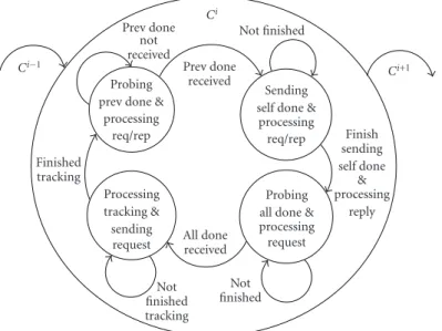
Figure 8shows a diagram of the system synchronization mechanism. This figure illustrates the camera states at the
Probing prev done &
processing req/rep
Sending self done &
processing req/rep Processing tracking & sending request Probing all done & processing request Prev done received All done received received Finished tracking Not finished tracking Not finished Finish sending self done & processing reply Ci−1 Ci+1
Figure8: Camera states at the synchronization point.
synchronization point. In the first state, the camera finishes its local tracking, and the processor sends out all of its saved requests. Then, the camera enters the second state and begins
to probe to see if a donemessage has been received from
the previous camera. If not, this node probes for incoming requests from the other nodes and replies to them while
waiting for the replies to its own requests. When the done
message is received from the previous camera the camera enters the third state. When all of its own requests are
fulfilled, it sends out adonemessage to the next camera. In
the fourth state, each camera node still processes requests
from other cameras, and keeps probing for the overalldone
message. Once it is received, a new cycle starts and the node returns back to the first state.
Thedonemessages in our protocol are sent by using aring
type of message routing to reduce the number of messages.
Thus, each node receives a done message only from its
previous neighbor node and passes that message to the next adjacent node when it finishes its own local operations and has received replies to all its requests for that cycle. However, based on the protocol, all the cameras need to make sure that all the others already have finished their tasks before starting
the next interval. Thus, a single pass of thedonemessage is
insufficient. If we haveNcameras (Ci,i = 0,. . .,N−1), a
single pass of thedonemessage will be fromC0toC1,C1to
C2, and so on. In this case,Ci−1will not know whetherCihas
finished its task since it will only receivedonemessages from
Ci−2. Thus, a second ring pass or a broadcast of an overall
done message will be needed. In the current implementation, the overall done message is broadcasted from the first camera in the ring since the message is the same for every camera.
This protocol can handle the problems caused by
com-munication delays and different processor loads and speeds,
and incorporates variable synchronization capabilities, so as to allow flexibility with accuracy tradeoffs. As will be
illus-trated inSection 5by Figures18and19, the synchronization
rate affects how soon a new label is received from the other
cameras. In this protocol, the synchronization rate can be set by the end user depending on the system specification.
Different synchronization rates are desirable in different
system setups. For instance, for densely overlapped cameras, it is necessary to have a shorter synchronization interval because an object can be seen by several cameras at the same time, and each camera may need to communicate with others frequently. On the other hand, for loosely overlapped cameras, the synchronization interval can be longer since the probability for communication is lower and as a result, excess communication due to superfluous synchronization points is eliminated.
3.5. Comparison of the number of messages for
a server-based scenario and for SCCS
3.5.1. A server-based system scenario for multicamera multiobject tracking
As stated before, server-based multicamera systems have a bandwidth scaling problem, and are limited by the server capacity. In order to illustrate the excessive number of messages and the load a server needs to handle, and compare these to the number of messages for our peer-to-peer
communication protocol, we will introduce a server-based
system scenarioin this section. In this server-based system, the nodes keep the server updated by sending it messages for each tracker in their FOV. To make a fair comparison between this scenario and our communication protocol, we assume that these messages are sent at the synchronization
points, which were defined inSection 3.4. In practice, due to
different processing rates of the distinct processors coupled
with communication delays, a server keeps the received data
buffered to provide consistent data transfer between the
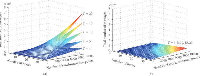
Numberof synchr onizationpoints 10000 8000 6000 4000 2000 0 Number of nodes20 30 10 0 T o tal n umber o f m essages 0 1 2 3 4 5 6 7 8 ×10⁶ T=20 T=15 T=10 T=5 T=1 (a) Numberof sync hronization points 10000 8000 6000 4000 2000 0 Numberof nodes20 30 10 0 T o tal n umber o f m essages 0 1 2 3 4 5 6 7 8 ×10⁶ T=1, 5, 10, 15, 20 (b)
Figure9: Comparison of the total number of messages for the server-based scenario and our peer-to-peer protocol: (a) and (b) show the total number of messages that need to be sent, forT=1, 5, 10, 15, 20, with the server-based scenario and our peer-to-peer protocol, respectively.
Tis the number of trackers in a camera view. For our peer-to-peer protocol, the same surface represents all different values ofT.
buffer size may need to be very large. Thus, we designed
this scenario so that the server does not need a buffer. The
nodes are required to wait at each synchronization point until they receive an overall done message from the server. At a synchronization point, each node needs to send a message for each tracker. These messages also indicate if the node has a request from any of the other nodes or not. Then, the server handles all these messages, determines the replies for each request, if there were any, and sends the replies to the corresponding nodes. The nodes update their trackers after receiving the replies, and acknowledge the server that they are done. After receiving a done message from all the nodes, the server sends an overall done message to the nodes so that nodes can move on. Based on this scenario, the total number of messages that are sent can be determined by using
Mserver=S×2×N+ N i=1 Ei+S× N i=1 Ti, (9)
whereSis the number of synchronization points, N is the
number of nodes/cameras and Ei is the total number of
events that will trigger requests in the view of camera Ci.
Tiis the total number of trackers in the view ofCi, and in
this formula, without loss of generality, it is assumed that,
for cameraCi,Tiremains the same during the video. In the
server-based case, all these messages go through the server, and this argument will be revisited below.
On the other hand, for our protocol employed in SCCS, the total number of messages that are sent around is equal to
MSCCS=S×(2×N−1) + 2×(N−1)×
N
i=1
Ei. (10)
It should be noted that, when calculating MSCCS, this
equation considers the worst possible scenario, where it is
assumed that all the cameras in the system view a common
portion of the scene, and all the events happen in this
overlapping region. This setup is highly unlikely since N
cameras will be setup so that they are spatially distributed,
and can cover a larger portion of the scene. In this
worst-casescenario, in our peer-to-peer protocol,Nnodes will send
N−1 request messages to the other nodes forEievents and
will receiveN−1 replies, hence the 2×(N−1)×N
i=1Ei term. At each synchronization point, each node will send a
donemessage to its next neighbor in the ring, and the first
node will send an overall done message toN−1 nodes, hence
theS×(2×N−1) term.
As seen from (10), contrary to the server-based scenario,
the total number of messages sent around by our system is independent of the number of trackers in each camera view, since the communication is done in a peer-to-peer manner.
This fact can also be seen by comparing Figures 9(a) and
9(b). These figures were obtained by settingEi=20 andTi=
T, for alli, whereT ∈ {1, 5, 10, 15, 20}. It should be noted
that Figures9(a)and9(b)are plotted so that their vertical
axes have the same scale. As can be seen inFigure 9(b), for
our peer-to-peer protocol, the same surface represents all
the different values ofT since the total number of messages
is independent of the number of trackers in each camera
view. In addition, (9) and (10), and Figure 9show that the
server-based scenario does not scale well with the increasing number of trackers in each camera view.
Now, we will compare the server-based system scenario
with our peer-to-peer system in terms of the messageloads
on the individual nodes, which is a very important point. By load, we mean the number of messages that go through a node. In other words, we will compare the number of messages handled by the server in the server-based scenario and by the individual nodes of the SCCS. For the
server-based scenario, all of the messages in (9) go through the
server. Whereas, in SCCS, one ordinary nodeihas to send
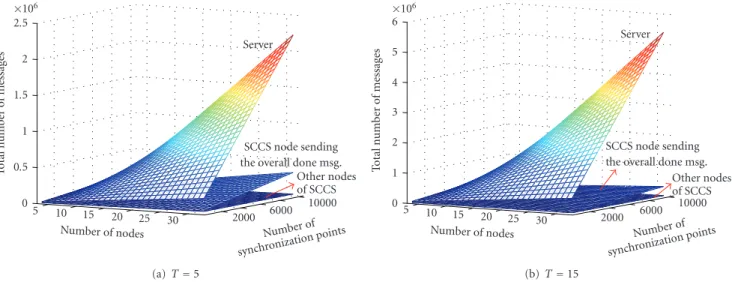
Number of synchronization points 10000 6000 2000 Number of nodes 30 25 20 15 10 5 T o tal n umber o f m essages 0 0.5 1 1.5 2 SCCS node sending the overall done msg.
Other nodes of SCCS (a)T=5 Number of synchronization points 10000 6000 2000 Number of nodes 30 25 20 15 10 5 T o tal n umber o f m essages 0 1 2 3 4 5 SCCS node sending the overall done msg.
Other nodes of SCCS
(b)T=15
Figure10: Comparison of the message loads: number of messages handled by the server in the server-based scenario and by the nodes of SCCS. (a) and (b) show the number of messages that are sent and received by the server and by the nodes of SCCS forT =5 andT=15, respectively. Numberof sync hronization points 10000 8000 6000 4000 2000 Number ofnodes20 25 30 15 10 5 T o tal n umber o f m essages 0 0.5 1 1.5 2 2.5 ×10⁶ Server-based SCCS (a)T=5 Number o f synchronization points 10000 6000 2000 Number of nodes 30 25 20 15 10 5 T o tal n umber o f m essages 0 1 2 3 4 5 6 ×10⁶ Server-based SCCS (b)T=15
Figure11: Comparison of the total number of messages for the server-based scenario and our peer-to-peer protocol forT=15 andT=20. For SCCS, it was assumed that all cameras have overlapping views and all events happen in overlapping region, which is highly unlikely.
2×S+(N−2)×Ei+Nk=1Ekmessages. The nodejsending the
overall done message has to sendS×N+(N−2)×Ej+
N
k=1Ek
messages, and receiveS+ (N−2)×Ej+
N
k=1Ekmessages.
These numbers are plotted in Figures10(a) and10(b) for
T =5 andT =15, respectively. As can be seen, the number
of messages sent or received by the server is much larger than the number of messages sent or received by any node of the SCCS.
Figures 11(a) and 11(b) compare the total number of
messages sent in the server-based scenario and our
peer-to-peer protocol for T = 5 and T = 15, respectively, where
Ti in (9) is set to be T, for alli ∈ 1,. . .,N. It should be
noted that this is the total number of messages. As stated
before, in the server-based scenario, all of these messages
go through the server. However, as seen in Figure 10, in
our peer-to-peer protocol, each node handles a portion of this total number of messages. Thus, the load on a server is much larger than the load on the individual nodes of the SCCS. Another very important point to note is that the total number of messages for the SCCS is obtained for the worst possible scenario, where it is assumed that all the cameras in the system view a common portion of the scene, and all the events happen in this overlapping region. This is a highly unlikely case, since in real-life settings not all the cameras
will have overlapping fields of view. Thus, in an N-node
system, when an event happens in the view of camera Ci,
it will only send request messages to the cameras which have overlapping fields of view withCi, and can see this event. In
other words, it will not need to sendN−1 messages, and
the 2×(N−1)×N