Calhoun: The NPS Institutional Archive
Theses and Dissertations Thesis Collection
2012-09
Exploring weakness in Long Term Evolution (LTE)
wireless standards
Tien, Too Huseh
Monterey, California: Naval Postgraduate School
NAVAL
POSTGRADUATE
SCHOOL
MONTEREY, CALIFORNIA
THESIS
Approved for public release; distribution is unlimited EXPLORING WEAKNESSES IN LONG TERM EVOLUTION (LTE) WIRELESS STANDARDS
by Too Huseh Tien September 2012
Thesis Co-Advisors: Weilian Su
REPORT DOCUMENTATION PAGE Form Approved OMB No. 0704-0188
Public reporting burden for this collection of information is estimated to average 1 hour per response, including the time for reviewing instruction, searching existing data sources, gathering and maintaining the data needed, and completing and reviewing the collection of information. Send comments regarding this burden estimate or any other aspect of this collection of information, including suggestions for reducing this burden, to Washington headquarters Services, Directorate for Information Operations and Reports, 1215 Jefferson Davis Highway, Suite 1204, Arlington, VA 22202-4302, and to the Office of Management and Budget, Paperwork Reduction Project (0704-0188) Washington DC 20503.
1. AGENCY USE ONLY (Leave blank) 2. REPORT DATE September 2012
3. REPORT TYPE AND DATES COVERED
Master’s Thesis
4. TITLE AND SUBTITLE Exploring Weakness in Long Term Evolution (LTE) Wireless Standards
5. FUNDING NUMBERS 6. AUTHOR(S) Too Huseh Tien
7. PERFORMING ORGANIZATION NAME(S) AND ADDRESS(ES)
Naval Postgraduate School Monterey, CA 93943-5000
8. PERFORMING ORGANIZATION REPORT NUMBER
9. SPONSORING /MONITORING AGENCY NAME(S) AND ADDRESS(ES)
N/A
10. SPONSORING/MONITORING AGENCY REPORT NUMBER
11. SUPPLEMENTARY NOTES The views expressed in this thesis are those of the author and do not reflect the official policy or position of the Department of Defense or the U.S. Government. IRB Protocol number ______N/A______.
12a. DISTRIBUTION / AVAILABILITY STATEMENT Approved for public release; distribution is unlimited
12b. DISTRIBUTION CODE
A
13. ABSTRACT (maximum 200 words)
The increasingly important role of Long Term Evolution (LTE) has increased security concerns among the service provider and end users and made security of the network even more indispensable. In this thesis, the LTE specifications are examined, and several security vulnerabilities of LTE mechanisms, in particular those that exist within the Layer 2 protocol of the LTE network, are identified. Among these mechanisms, the power control mechanism for LTE is further explored. The unprotected power control signal together with the Cell Radio Network Temporary Identifier (CRNTI) can be exploited to trick the victim User Equipment (UE) to transmit at a much higher than required power, which introduces significant inter-cell interference to adjacent base stations, evolved NodeB (eNodeB). The ways that an attacker can maliciously manipulate the control field of the power control mechanism are demonstrated. The effectiveness of such attack is evaluated with respect to the victim UEs and the adjacent eNodeBs. The impacts include reduction of battery lifespan of victim UE to 33% of the original battery lifetime and reduction in reverse channel signal-to-interference ratio (SIR) of adjacent eNodeB by 3.4 dB causing a decrease in throughput of 37%.
14. SUBJECT TERMS Long Term Evolution (LTE), Security, Power control, Vulnerabilities 15. NUMBER OF PAGES 103 16. PRICE CODE 17. SECURITY CLASSIFICATION OF REPORT Unclassified 18. SECURITY CLASSIFICATION OF THIS PAGE Unclassified 19. SECURITY CLASSIFICATION OF ABSTRACT Unclassified 20. LIMITATION OF ABSTRACT UU
NSN 7540-01-280-5500 Standard Form 298 (Rev. 2-89)
Approved for public release; distribution is unlimited
EXPLORING WEAKNESSES IN LONG TERM EVOLUTION (LTE) WIRELESS STANDARDS
Too Huseh Tien
Defence Science & Technologies Agency
B.Eng (Electrical Engineering), Nanyang Technological University, 2005
Submitted in partial fulfillment of the requirements for the degree of
MASTER OF SCIENCE IN ELECTRICAL ENGINEERING
from the
NAVAL POSTGRADUATE SCHOOL September 2012
Author: Too Huseh Tien
Approved by: Weilian Su
Thesis Co-Advisor
Tri T. Ha
Thesis Co-Advisor
R. Clark Robertson
ABSTRACT
The increasingly important role of Long Term Evolution (LTE) has increased security concerns among the service provider and end users and made security of the network even more indispensable. In this thesis, the LTE specifications are examined, and several security vulnerabilities of LTE mechanisms, in particular those that exist within the Layer 2 protocol of the LTE network, are identified. Among these mechanisms, the power control mechanism for LTE is further explored. The unprotected power control signal together with the Cell Radio Network Temporary Identifier (CRNTI) can be exploited to trick the victim User Equipment (UE) to transmit at a much higher than required power, which introduces significant inter-cell interference to adjacent base stations, evolved NodeB (eNodeB). The ways that an attacker can maliciously manipulate the control field of the power control mechanism are demonstrated. The effectiveness of such attack is evaluated with respect to the victim UEs and the adjacent eNodeBs. The impacts include reduction of battery lifespan of victim UE to 33% of the original battery lifetime and reduction in reverse channel signal-to-interference ratio (SIR) of adjacent eNodeB by 3.4 dB causing a decrease in throughput of 37%.
TABLE OF CONTENTS
I. INTRODUCTION...1 A. BACKGROUND ...1 B. PROJECT OBJECTIVE ...7 C. SCOPE OF THESIS ...7 D. APPROACH/STRUCTURE ...8II. LITERATURE REVIEW ...9
A. OVERVIEW ...9
B. AUTHENTICATION PROTOCOL AND KEY MANAGEMENT ENHANCEMENT IN LTE ...9
C. WEAKNESS OF IP CONVERGED LTE NETWORK ...10
D. VULNERABILITIES OF NON-ACCESS-STRATUM (NAS) OF E-UTRAN ...10
E. THREATS EXPLOITING LAYER 2 INFORMATION ...11
F. INVESTIGATION OF LTE SPECIFICATION ...11
1. Malicious Modification of Control PDU Type Reserve Field ...12
2. Prioritized Retransmission of Traffic Data ...12
3. Malicious Modification of Power Control Mechanism ...12
III. TECHNICAL BACKGROUND ...13
A. LTE TECHNOLOGY BASICS ...13
1. OFDM ...13
2. OFDMA ...17
3. SC-FDMA ...17
4. MIMO Concept ...19
5. Generic Frame Structure ...21
6. Physical Resource Block ...22
7. Supportable Frequency Bands...23
B. LTE NETWORK ARCHITECTURE OVERVIEW ...24
C. NETWORK AND PROTOCOL ARCHITECTURE ...28
1. MAC [28] ...29 2. RLC [30] ...31 3. PDCP [31] ...33 4. RRC [33] ...34 D. THREAT MODEL...34 E. LTE SECURITY ...34
1. Control Plane Security ...35
2. User Plane Security ...36
IV. POTENTIAL WEAKNESS OF LTE SECURITY ...39
A. CELL TYPE ...39
B. INTERFERENCE ...39
C. UPLINK POWER CONTROL ...41
2. Closed Loop Power Control Mechanism (Modified) ...44
D. SCHEDULING GRANT ...46
1. Downlink Control Signaling...47
2. Decoding and Search Space ...50
E. APPROACH ...52
1. Stage 1– Acquisition of Cell Radio Network Temporary Identifier (CRNTI) ...53
2. Stage 2- Synchronization of Frame ...53
3. Stage 3- Message Injection ...54
a. Power Requirement for Message Injection ...54
F. IMPACT ...58
1. Depletion of Battery Power ...58
2. Reduction of Reverse Channel SIR ...59
V. CONCLUSIONS AND FUTURE WORK ...69
A. CONCLUSIONS ...69
B. FUTURE WORK ...69
1. Verification and Validation of Desired Received SINR ...69
2. Investigation on Other Control Messages...70
APPENDIX A- MATLAB SIMULATIONS ...71
A. CALCULATION AND PLOT OF FALSE SIGNAL TO LEGITIMATE SIGNAL RATIO ...71
B. CALCULATION AND PLOT OF SIRAVE, NORMAL ...72
C. CALCULATION AND PLOT OF SIRAVE, MAXIMUM ...72
LIST OF REFERENCES ...75
LIST OF FIGURES
Figure 1. 3GPP family technology evolution. From [2]...2
Figure 2. 3GPP LTE evolution country map. From [5]. ...3
Figure 3. Representation of single-carrier transmission and OFDM in the frequency domain. From [18]. ...13
Figure 4. Multipath-induced time delays result in ISI. From [19]. ...14
Figure 5. Frequency-time representation of an OFDM signal. From [20]. ...15
Figure 6. OFDM signal generation chain. From [20]...16
Figure 7. Contrast between transmission schemes of OFDM and OFDMA. From [18]. ...17
Figure 8. SC-FDMA signal generation chain. From [18]. ...18
Figure 9. Representation of OFDM and SC-FDMA signals. From [18]. ...19
Figure 10. Principle of spatial multiplexing. From [20]...20
Figure 11. Channel matrix H. From [21]. ...20
Figure 12. LTE frame structure type 1. From [22]. ...21
Figure 13. LTE frame structure type 2 (5 ms switch point periodicity). From [22]. ...22
Figure 14. Downlink resource grid. From [24] ...23
Figure 15. High level architecture of LTE. After [25]. ...25
Figure 16. Functional split between the E-UTRAN and EPC. From [26]. ...26
Figure 17. User plane protocol stack. After [26]. ...27
Figure 18. Control plane protocol stack. After [26]. ...28
Figure 19. Transmission of data in LTE downlink in time domain. From [27]. ...28
Figure 20. Logical channels in LTE. After [28]. ...29
Figure 21. Transport channels in LTE. After [28]. ...30
Figure 22. Downlink mapping of logical to transport channels in LTE. From [29]. ...30
Figure 23. Uplink mapping of logical to transport channels in LTE. From [29]. ...31
Figure 24. Overview model of RLC sub-layer. From [30]. ...32
Figure 25. RLC PDU structure. From [26]. ...33
Figure 26. Functional view of PDCP layer. From [30]. ...33
Figure 27. Threat model for LTE network. After [25]. ...35
Figure 28. Control plane layered security. After [34]. ...36
Figure 29. User plane layered security. After [34] ...37
Figure 30. Center cell antenna bearing orientation diagram. From [20]. ...40
Figure 31. Diagram of the network cell set-up with 120-degree directional antenna. After [35]. ...40
Figure 32. Power control parameters transmitted from eNodeB to UE. ...42
Figure 33. Block diagram of steps involved in the closed loop power control mechanism. ...43
Figure 34. Closed loop power control modified by adversary. ...44
Figure 35. Structure of MAC RAR. From [28]. ...46
Figure 36. MAC PDU consisting of MAC header and MAC RARs. From [28]. ...46
Figure 37. Overview of PCFICH processing. From [29]. ...47
Figure 39. Downlink signal processing of the eNodeB. After [29]. ...50 Figure 40. Search space of UEs in the control region. ...52 Figure 41. Set-up position for MITM attack. ...56 Figure 42. Relation between the proximity of the attacker to the victim UE and the
required attacker’s transmitted power (n=4). ...57 Figure 43. Battery lifespan of four LTE phones by applications. From [38]. ...59 Figure 44. Reverse channel interference analysis for edge area. After [37]. ...60 Figure 45. Signal-to-interference ratio for various combinations of UEs’ transmitted
power (UE1, UE2, UE3 and UE4 range from 10 mW to 200 mW). ...64 Figure 46. Signal-to-interference ratio for first 100 combination of UEs’ transmitted
power to compute SIRAve,normal. ...65 Figure 47. Signal-to-interference ratio for various combinations of UEs’ transmitted
power (UE1, UE2 and UE3 are fixed at 200 mW). ...67
LIST OF TABLES
Table 1. Comparison of parameters between LTE and its predecessors. From [3]. ...3
Table 2. Major parameter for LTE Release 8. After [6]. ...6
Table 3. User equipment categories for LTE Release 8. After [6]. ...6
Table 4. Uplink-downlink configuration for LTE frame structure type 2 [22]. ...22
Table 5. Resource block configuration for different channel bandwidths. From [24]. ..23
Table 6. LTE operating band. From [24]. ...24
Table 7. TPC commands with their corresponding values. From [36]. ...45
Table 8. Content for uplink scheduling grants. From [36]...45
Table 9. DCI format with corresponding usage. From [29]...49
Table 10. Required transmitted power of attacker for various false-signal-to-legitimate-signal ratio. ...57
Table 11. Various input combinations of UEs’ transmitted power to compute SIRAve,normal. ...64
Table 12. Various input combinations of UEs’ transmitted power to compute SIRAve,maximum. ...66
LIST OF ACRONYMS AND ABBREVIATIONS
3GPP Third Generation Partnership Program
4G Fourth Generation
AKA Authentication and Key Agreement
AM Acknowledged Mode
AS Access Stratum
BCCH Broadcast Control Channel
BCH Broadcast Channel
BPSK Binary Phase Shift Keying
CCCH Common Control Channel
CCE Control Channel Element
CCI Co-channel Interference
CFO Carrier Frequency Offset
CN Core Network
CP Cyclic Prefix
CRNTI Cell Radio Network Temporary Identifier
CRC Cyclic Redundancy Check
CSG Closed Subscriber Group
DCCH Dedicated Control Channel
DCI Downlink Control Message
DL-SCH Downlink Shared Channel
DoS Denial of Service
DRX Discontinuous Reception
DTCH Dedicated Traffic Channel
DwPTS Downlink Pilot Timeslot
EAKA Enhanced EPS-AKA
EAP-TLS Extensible Authentication Protocol-Transport Layer Security
E-UTRA Evolved Universal Terrestrial Radio Access
E-UTRAN Evolved Universal Terrestrial Radio Access Network
EDGE Enhanced Data rates for Global Evolution
EPC Evolved Packet Core
EPS Evolved Packet System
ESIM Enhanced Subscriber Identity Module
FDD Frequency-Division Duplexing
FFT Fast Fourier Transform
GP Guard Period
GSA Global mobile Suppliers Association
HARQ Hybrid Automatic Repeat Request
HPSA High Speed Packet Access
HSS Home Subscriber Server
IFFT Inverse Fast Fourier Transformation
ICI Inter-Carrier interference
IMT International Mobile Telecommunications
IP Internet Protocol
IPSec Internet Protocol Security
ISI Inter-Symbol-Interference
LEAP Lightweight Extensible Authentication Protocol
LTE Long Term Evolution
LTE/SAE Long Term Evolution/System Architecture Evolution
MAC Medium Access Control
MCH Multicast Channel
MBMS Multimedia Broadcast Multicast Services
MBSFN Multicast-Broadcast Single Frequency Network
MCCH Multicast Control Channel
MCS Modulation and Coding Scheme
MME Mobility Management Entity
ME Mobile Equipment
MIMO Multiple-Input Multiple-Output
MITM Man-In-The-Middle attack
MTCH Multicast Traffic Channel
NAS Non-Access Stratum
OFDMA Orthogonal Frequency-Division Multiple-Access
P-GW Packet Data Network Gateway
PAP Password Authentication Protocol
PAPR Peak-to-Average Power Ratio
PBCH Physical Broadcast Channel
PCFICH Physical Control Format Indicator Channel
PCCH Paging Control Channel
PCH Paging Channel
PDCCH Physical Downlink Common Control Channel
PDSCH Physical Downlink Shared Channel
PDCP Packet Data Convergence
PDU Protocol Data Unit
PHICH Physical Hybrid-ARQ Indicator Channel
PRACH Physical Random Access Channel
PRB Physical Resource Block
PUCCH Physical Uplink Control Channel
PUSCH Physical Uplink Shared Channel
QAM Quadrature Amplitude Modulation
QoS Quality of Service
QPSK Quadrature Phase-Shift Keying
RACH Random Access Channel
RAR Random Access Response
REs Resource Elements
REGs Resource Element Groups
RF Radio Frequency
RLC Radio Link Control
RNTI Radio Network Temporary Identifier
ROHC Robust Header Compression
RRC Radio Resource Control
S-GW Serving Gateway
SAE System Architecture Evolution
SDU Service Data Units
SIR Signal-to-Interference Ratio
SINR Signal-to-Interference and Noise Ratio
SNR Signal-to-Noise Ratio
SKC Session Keys Context
TDD Time Division Duplexing
TDMA Time-Division Multiple-Access
TPC Transmit Power Control
UE User Equipment
UEID UE Identification
UL-SCH Uplink Shared Channel
UMTS Universal Mobile Telecommunications System
UpPTS Uplink Pilot Timeslot
W-CDMA Wideband Code-Division Multiple Access
EXECUTIVE SUMMARY
The rapid increase in data usage in mobile communication systems has led to the development of the fourth generation (4G) Long Term Evolution (LTE) standard. LTE is the current generation wireless data communications standard that is poised to dominate mobile data connectivity in both the commercial and military arenas because of its very high data rate capabilities. The increasingly important role of LTE has increased security concerns among the service provider and end users and made security of the network even more indispensable.
The literature related to the LTE network, in particular, that which is related to the security issues, is reviewed and the security vulnerabilities identified in the available literatures are discussed briefly. In this thesis, the LTE specifications are examined and several security vulnerabilities of LTE mechanisms, in particular those that exist within the Layer 2 protocol of the LTE network, are identified. The identified potential weaknesses include malicious modification of the control protocol data unit (PDU) type reserve field, prioritized retransmission of traffic data, and malicious modification of the power control mechanism.
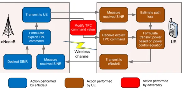
In this thesis, the focus is on exploring the power control mechanism for LTE. The objectives of power control are to improve the system capacity, coverage and user experience, while at the same time reduce the power consumption of the User Equipment (UE). Fundamentally, uplink power control for LTE is a combination of an open-loop mechanism, where the UE transmit power depends on estimates of the downlink path loss, and a closed loop mechanism, where the network directly controls the UE transmit power by means of explicit transmitter power-control (TPC) commands transmitted in the downlink. This closed loop mechanism is computed dynamically and updated from sub-frame to sub-sub-frame. An adversary can inject false power-control commands to control the UE transmit power, as shown in Figure 1.
Figure 1. Modified power control mechanism.
The unprotected power control signal together with the Cell Radio Network Temporary Identifier (CRNTI) can be exploited to change the intended behavior of the UE. The CRNTI provides unique end User Equipment identification (UEID) at the cell level and is assigned to the associated UE by the network during the initial establishment of uplink synchronization. An adversary can exploit the fact that CRNTI is transmitted in the clear and misuse it for malicious activities.
The ways that an attacker can maliciously manipulate the control field of the power control mechanism are demonstrated in this thesis. The attacker acts as a combination of base station, evolved NodeB (eNodeB), and the UE. Initially, the attacker impersonates a UE and connects to the genuine eNodeB to obtain the cell–specific reference signal. The attacker at a later stage presents itself as a bogus eNodeB and generates false messages to the victim UE. The attacker can perform message injection attack on the victim UE in three stages. Stage 1 involves the extraction of messages between the victim UE and the eNodeB to obtain CRNTI. Stage 2 involves the calculation of the timing advance to synchronize the false message frame to the victim UE. Stage 3 involves the injection of false messages with the TPC field adjusted to the
designated value to change the behaviors of the victim UE. The correlation and graph for the required power of the injected message for varying received false-signal-to-legitimate-signal is also derived.
The effectiveness of such an attack with respect to the victim UEs and adjacent eNodeBs are evaluated. The impacts include reduction of battery lifespan of victim UE and reduction in reverse channel signal-to-interference ratio (SIR) of adjacent eNodeB.
The interference generated by the victim UE in a 120-degree sectoring cell is examined. A combination of these interferences creates a cascading effect on adjacent eNodeBs, and the received SIR at the eNodeB is derived. From the derivation, it is observed that SIR is dependent on the power transmitted by the UEs, and Matlab simulation is performed to generate the average SIR. It is indicated in the simulation results that the received SIR at the eNodeB decreases from a nominal value of 11.7 dB to 8.3dB when the interfering sources are transmitting at maximum power.
In general, a modulation and coding scheme (MCS) with a higher throughput requires a higher SIR to operate in. The decrease in SIR leads to the adoption of an MCS type with a lower throughput. The MCS is lowered from MCS-10, with a corresponding maximum throughput of 3.2 bits per second per hertz, to MCS-8, with a corresponding maximum throughput of 2.0 bits per second per hertz. The maximum throughput of the legitimate UE is reduced by 37.5%.
ACKNOWLEDGMENTS
I would like to thank my thesis advisors, Prof Tri Ha and Prof Weilian Su, for their guidance and motivation to complete this thesis. I would also like to thank my wonderful wife, Kim Hong, my family, and friends for their continuous support during my study in Naval Postgraduate School.
I.
INTRODUCTION
A. BACKGROUND
“LTE is the next step in user experience, enhancing more demanding application such as interactive TV, mobile video blogging, advanced gaming, and professional services. Data rates are significantly higher. LTE supports a full [internet protocol] IP-based network and harmonization with other radio access technologies.” [1]
The rapid increase in data usage in mobile communication systems has led to the development of fourth generation (4G) wireless technologies, which includes Long Term Evolution (LTE) and Worldwide Interoperability for Microwave Access (WiMAX). LTE is a standard developed by the Third Generation Partnership Program (3GPP) Long Term
Evolution/System Architecture Evolution (LTE/SAE), a consortium of
telecommunications associations formed in order to define communication standards, and is specified in the 3GPP’s Release 8 document series, with minor enhancements described in Release 9.
LTE belongs to the GSM path for mobile broadband and evolved after Enhanced Data rates for Global Evolution (EDGE), Universal Mobile Telecommunications System (UMTS), High Speed Packet Access (HPSA) and HSPA Evolution (HSPA+). The evolutionary path is illustrated in Figure 1.
The first release of 3G provided by 3GPP in 2000 is known as “Release 99”. This defines the wideband code-division multiple access (W-CDMA) and UMTS standards. In 2001, a new feature, “all-IP core network”, was added to Release 99, and it evolved to Release 4. HPSA includes Release 5 and Release 6. Release 5 introduced the high speed downlink packet access (HSDPA) in 2002 and Release 6 introduced the high speed uplink packet access (HSUPA) and included more features like multimedia broadcast multicast services (MBMS) and integration with wireless local area network (LAN) in 2005. Release 7 introduced HSPA+ in 2007 and primarily deals with the development of specification like latency and quality of service (QoS) improvement and real time applications.
Although the HSPA systems offer significant improvement in performance over previous UMTS systems, their designs were limited by compatibility requirement in the UMTS specification. In addition, with the emergence of packet-based mobile broadband system like WiMAX, it is imperative for 3GPP to develop new standards and mobile technologies to ensure competitiveness for the next decade and beyond in order to meet the increasing demand of the network services, in terms of higher data rates, reduced latency, improved system capacity and coverage. LTE/SAE proposes to fulfill these requirements by using an IP converged architecture system which is able to work across multiple access networks. Thus, LTE was first introduced in Release 8 in 2008, while Release 9 is the LTE release with SAEs enhancement and the interoperability of LTE and WiMAX.
The overall high level objective of LTE is to provide an extremely high performance radio-access technology that provides full vehicular speed mobility and can coexist with HSPA and other previous networks. With the scalable bandwidth functionality of LTE, operators are able to migrate their networks and users from HSPA to LTE over time with ease.
Figure 1. 3GPP family technology evolution. From [2].
LTE is able to provide unprecedented performance in terms of peak data rates, delay, and spectrum efficiency to the network when compared with its predecessors. LTE can provide up to 100 Mbps downlink data rate and up to 50 Mbps uplink data; this is four times faster than previous HSPA+ data rates. The comparison of peak data rates and other parameters between LTE and its predecessors are shown in Table 1.
Table 1. Comparison of parameters between LTE and its predecessors. From [3].
WCDMA (UMTS)
HSPA
(HSDPA/HSUPA) HSPA+ LTE Maximum downlink speed (bps) 384 k 14 M 28 M 100 M
Maximum uplink speed (bps) 128 k 5.7 M 11 M 50 M
Latency round trip time
(approximate) 150 ms 100 ms
50ms
(Max) ~10 ms
3GPP releases Rel 99/4 Rel 5/6 Rel 7 Rel 8
Approximate years of initial roll
out 2003/4
2005/6 HSDPA
2007/8 HSUPA 2008/9
Access methodology CDMA CDMA CDMA
OFDMA/SC-FDMA
A LTE evolution update report researched and published by Global mobile Suppliers Association (GSA) dated January 5, 2012, [4] confirms that 49 LTE operators have already launched commercial services. These 49 LTE operators have launched LTE networks services in 29 countries, which include Armenia, Australia, Austria, Bahrain, Belarus, Brazil, Canada, Denmark, Estonia, Finland, Germany, Hong Kong, Hungary, Japan, Kuwait, Latvia, Lithuania, Norway, Philippines, Poland, Puerto Rico, Saudi Arabia, Singapore, South Korea, Sweden, UAE, Uruguay, USA, and Uzbekistan. The countries with deployed LTE services are shaded in red in Figure 2.
The GSA report also confirms that 285 operators in 93 countries have committed to commercial LTE network deployments or are engaged in trials, technology testing or studies. This includes the 49 commercial LTE network that are already launched, 117 deployments that are in progress or planned in 76 countries, and another 59 operators in 17 other countries that are engaged in LTE technology trials, tests or studies.
This report suggests that the operators around the world have strengthened their commitment and investment in the LTE technology, and GSA forecast that there will be 119 commercial LTE networks in more than 50 countries by the end 2012.
The motivations for the growth of interest in LTE are as follows: continued competitiveness of the 3G system, user demand for higher data rates and QoS, packet switch optimized system, continued demand for reduced Capital and Operational Expenditures (CAPEX and OPEX), low complexity, and avoidance of unnecessary fragmentation of technologies for paired and unpaired band operation [6].
There are several key features of LTE discussed in [7]. These features are access scheme, data rate, latency, mobility, spectrum allocation, frequency bands, scalable bandwidth, cell size, supported users, internetworking with legacy network, packet switched radio interface and support or Multicast-Broadcast Single Frequency Network (MBSFN).
For the access scheme feature, LTE uses orthogonal frequency-division multiple access (OFDMA) for the downlink and single carrier frequency-division multiple access (SC-FDMA) for the uplink. The major parameters for LTE are shown in Table 2.
For the date rate feature, the peak download rates can support up to 299.6 Mbit/s and upload rates up to 75.4 Mbit/s, depending on the User Equipment (UE) category. Five different terminal classes have been defined from a voice centric class up to a high-end terminal that supports peak data rates. The download and upload rates for respective UE Categories are shown in Table 3.
For the latency feature, in optimal conditions, the data transfer latency is low at sub-5 ms for small IP packets. This is lower for handover and connection set-up time than with previous radio access technologies.
For mobility features, there is also an improved support for mobility, exemplified by support for terminals moving at up to 350 km/h or 500 km/h depending on the frequency band [8].
For the spectrum allocation feature, the LTE supports frequency-division duplexing (FDD) and time-division duplexing (TDD) communication systems as well as half-duplex FDD with the same radio access technology.
For the frequency bands feature, LTE supports all frequency bands currently used by International Mobile Telecommunications (IMT) systems. For the scalable bandwidth feature, LTE includes increased spectrum flexibility, with 1.4 MHz, 3 MHz, 5 MHz, 10 MHz, 15 MHz and 20 MHz wide cells standardized.
For the cell size feature, LTE supports cell sizes from tens of meters radius (femto and picocells) up to 100 km radius macrocells. In the lower frequency bands to be used in rural areas, 5 km is the optimal cell size, 30 km having reasonable performance, and up to 100 km cell sizes supported with acceptable performance. In city and urban areas, higher frequency bands (such as 2.6 GHz in the EU) are used to support high speed mobile broadband. In this case, cell sizes may be 1 km or even less.
For the supported user feature, LTE supports at least 200 active clients in every 5 MHz cell [9]. For internetworking with legacy network, LTE supports the inter-operation and co-existence with legacy standards.
For the MBSFN feature, LTE can deliver services such as Mobile TV using the LTE infrastructure and is a competitor for DVB-H-based TV broadcast.
Several key enablers are required to achieve the aggressive performance targets of the LTE. The identified key enablers for the LTE are orthogonal frequency-division multiplexing (ofdm), multiple-input multiple-output (MIMO), and system architecture evolution (SAE). [10]
The OFDM technology is an enabler in LTE because of its capability to transmit at high data bandwidth efficiently while providing resilience to reflection and interference. OFDMA is used in the downlink to achieve high peak data rates in high
spectrum bandwidth and SC-FDMA is used in the uplink because its small peak-to-average power ratio; the more constant power enables high RF power amplifier efficiency in mobile handsets, which is an important factor for battery power equipment.
Table 2. Major parameter for LTE Release 8. After [6].
Access Scheme Uplink DFTS-OFDM Downlink OFDMA Bandwidth 1.4, 3, 5, 10, 15, 20 MHz Minimum TTI 1 ms Sub-carrier spacing 15 kHz
Cyclic prefix length
Short 4.7 µs Long 16.7 µs
Modulation QPSK, 16QAM, 64QAM
Spatial multiplexing
Single layer for Uplink per UE Up to 4 layers for downlink per UE
MU-MIMO supported for uplink and downlink
Table 3. User equipment categories for LTE Release 8. After [6].
Category 1 2 3 4 5
Peak rate (Mbps)
Downlink 10 50 100 150 300
Uplink 5 25 50 50 75
Capability for physical functionalities
RF bandwidth 20MHz Modulation Downlink QPSK, 16QAM, 64 QAM Uplink QPSK, 16QAM Multi-antenna
2 RX diversity Assumed in performance requirements
2x2 MIMO
Not
supported Mandatory
4x4 MIMO Not supported Mandatory
The MIMO technique is an enabler because one of the main problems encountered by previous telecommunications systems was that multiple signals arose from the many reflections that are encountered along the path. These signals would reach the destination at different times and result in a disrupted waveform signal. With the
usage of MIMO, these additional signal paths can be used as an advantage to increase the throughput. MIMO antenna technology enables ten times as many users per cell as 3GPP’s original WCDMA access technology [6].
Lastly, the SAE enables the system architecture to evolve in order to handle the very high data rate and low latency requirements for 3G LTE. One of the significant changes to the system architecture is that a number of the functions previously handled by the core network have been transferred out to the periphery. This leads to a “flatter” form of network architecture and allows direct routing of the data to the destination, which in turn reduces the latency times.
With the superior features that LTE can provide, LTE is the next generation wireless data communications standard that is poised to dominate mobile data connectivity in both the commercial and military. In the commercial sector, a disruption in service due to security reasons can jeopardize the reputation and reduce the revenue of the service provider. In the military sector, the integrity and the timely transmission of data are of upmost importance. Any compromise may result in failure of the mission.
Security is indispensable for secured communication between users and mobile networks. The increasingly important role of LTE has brought about a number of security concerns among the service provider and end users. The aim of this thesis is to provide a comprehensive analysis on the potential weakness of the LTE protocol.
B. PROJECT OBJECTIVE
Security within the LTE system has become extremely important to ensure secured communication of the user terminals accessing network services. The security and robustness of the LTE standard, especially those of its control channels in Layer 2, namely, Radio Link Control (RLC), Medium Access Control (MAC) and Packet Data Convergence (PDCP), need to be further examined.
C. SCOPE OF THESIS
The scope of the thesis includes the review of the LTE protocol standards and the assessment of existing threats to LTE system, followed by an exploration of methods of
hacking into and manipulating the control channel without the other party's knowledge. This thesis research can serve as a starting point to protect, as well as to exploit, protocol weaknesses in LTE and, thus, open exploitation space.
D. APPROACH/STRUCTURE
The literature related to the LTE network is briefly discussed in Chapter II. In particular, available literature related to security issues is reviewed and security vulnerabilities are identified. The LTE specifications are examined, and several other potential security weaknesses of the features and mechanisms, especially those related to the control channels within the LTE network’s Layer 2 protocol, are identified.
In Chapter III, some of the important technical aspects of 3GPP are discussed. Some basic technologies and methods employed in LTE, which include OFDM, OFDMA, SC-FDMA and MIMO, are explored. A general overview of LTE architecture, the different protocol layers and their interaction within the LTE network, followed by the threat model and LTE’s security architecture are presented in Chapter III. Finally, the details of sub-layer protocols, namely, RLC, MAC and PDCP within the LTE network’s Layer 2 protocol, are elaborated on.
In Chapter IV, LTE’s power control mechanisms are explored and the unprotected power control signal is exploited to conduct attacks on UEs and degrade their intended services. The ways that an adversary can maliciously manipulate the power control mechanism’s control field in order to sabotage the victim UE are demonstrated. This chapter concludes by evaluating the impacts of the attack.
In Chapter V, the results of the thesis are summarized and the potential research issues related to the security of LTE are discussed.
II.
LITERATURE REVIEW
A. OVERVIEW
The majority of research related to LTE began in 2008, after the release of the first LTE standard by 3 GPP. As the objective of the thesis is to examine the security and robustness of the LTE standard, the literature review is related to materials discussing the security aspect of LTE. A relatively small amount of research has been done on the security of LTE, and only a limited number of security exploitations in LTE have been discussed extensively in the published literature. There is, however, literature that serves to provide a background and presents a tutorial overview of proposed security mechanisms in Evolved Packet System (EPS), which lists some open security issues and key threats in LTE at that time.
The threats discussed in [11] are the illegal access and usage of user’s and mobile equipment’s (ME’)s identities, the tracking of user based on UE’s identity and signaling messages, the illegal access and usage of keys used in security procedures, the malicious modification of UE parameters to deny UE of normal services, the tampering with the system information broadcasted to the Evolved Universal Terrestrial Radio Access Network (E-UTRAN), the denial-of-service (DoS) to the UE, and the replaying attacks which affect the integrity of data. These threats to the LTE network were not further elaborated in [11].
B. AUTHENTICATION PROTOCOL AND KEY MANAGEMENT
ENHANCEMENT IN LTE
Several researchers have done work to enhance the robustness of the security protocol and mechanism in LTE.
The authors in [12] describe the LTE security architecture and mobility procedures related to key management techniques in order to minimize the effects of a possible key compromise in the access points. They go on to compare in detail LTE’s key management security properties with the session keys context (SKC) concept. The
authors conclude that LTE could benefit from the SKC type of key management since SKC concept is simpler and allows higher key distributor scalability, while the security properties are quite similar.
The authors in [13] survey and compare three authentication protocols candidates: Password Authentication Protocol (PAP), Lightweight Extensible Authentication Protocol (LEAP) and Extensible Authentication Protocol-Transport Layer Security (EAP-TLS) for LTE network. The conclusion is that PAP and LEAP are vulnerable to dictionary attacks. EAP-TLS can provide reliable security performance, but has considerable overhead.
The research in [14] examines the weaknesses and strength of the Authentication and Key Agreement protocol (EPS-AKA) and identifies the protocol’s potential weaknesses. A new authentication protocol, Enhanced EPS-AKA (EAKA), is proposed which provides full (online) mutual entity authentication between ESIM (Enhanced Subscriber Identity Module) and Home Subscriber Server (HSS) and removes the need for delegated authentication.
C. WEAKNESS OF IP CONVERGED LTE NETWORK
A survey of security threats conducted in [15] shows that the reason for the unexpected service disruption and disclosure of information is the inherent weakness of the converged Internet Protocol (IP) architecture of the LTE. The IP network is susceptible to conventional attacks like IP address spoofing, user ID theft, theft of service and DoS and intrusion attacks; these attacks are extended to the LTE network. In addition, as mentioned in [16], the network is vulnerable to the known computer network attack techniques such as man-in-the-middle (MITM), eavesdropping, Trojan, virus and malware. Security vulnerabilities in the IP can jeopardize the entire IP converged LTE network.
D. VULNERABILITIES OF NON-ACCESS-STRATUM (NAS) OF E-UTRAN
The authors in [40] study the vulnerabilities of the Non-Access Stratum (NAS) of E-UTRAN and illustrate attacks that exploit these vulnerabilities. The transmission of the unprotected Radio Resource Control (RRC) messages and the transmission of
International Mobile Subscriber Identity (IMSI) in plain text without confidentiality and integrity protection are discussed in the article. In addition, the CRNTI information in Layer 1 provides attackers the opportunities to track an UE across cells. The exploitation of these vulnerabilities allows the attackers to launch efficient and effective DoS attacks on the eNodeB.
E. THREATS EXPLOITING LAYER 2 INFORMATION
To the best of our knowledge, [17] is the only available reference that deals with identifying threats and attacks by manipulating the information in MAC and RRC signaling messages. The focus of [17] is on the security and privacy threats in radio interface between eNodeB and the UE. There are two identified threats; the first threat is the tracking of UE location based on the unique CRNTI, cell level measurement reports or packet sequence numbers, and the second threat is the message insertion attack in UE’s long discontinuous reception (DRX) period.
The long DRX period allows the UE to periodically switch off the processing elements to save on the limited battery power and improves on power consumption’s efficiency. However, this introduces extended delays when the UE needs to transmit or receive data and may pose a security loophole for the system while the UE is “inactive” during the long DRX period. The UE is vulnerable to attacks during this period; these attacks includes false buffer status report attack which either steal bandwidth by changing the packet scheduling behavior or changes the behavior of load balancing /admission control algorithms in the eNodeB.
F. INVESTIGATION OF LTE SPECIFICATION
Investigation of the LTE specifications revealed that there are vulnerabilities within the LTE’s Layer 2 protocol. In this thesis, these vulnerabilities are identified and the working principles are discussed briefly. The focus is on exploring LTE’s power control mechanism. The ways to exploit the unprotected fields of the power control message and attacks to the victim UE are detailed in Chapter IV.
Some of the potential vulnerabilities include the malicious modification of control PDU type reserve field, the prioritized retransmission of traffic data, and the malicious modification of power control mechanism. These are discussed in the following sections.
1. Malicious Modification of Control PDU Type Reserve Field
The STATUS PDU is sent by the receiver to feedback on the status of the received PDU. The control PDU type field is 3 bits and the STATUS PDU is indicated by 000, while 001-111 are reserved. PDUs with this reserved coding will be discarded by the receiving entity for this release of the protocol (Release 10). The adversary can maliciously adjust the control PDU type field to the reserved value and the recipient will not be able to recognize and subsequently discard the STATUS PDU.
2. Prioritized Retransmission of Traffic Data
The Radio Link Control (RLC) priority ruling [29] states that “the transmitting side of an Acknowledged mode (AM) RLC entity shall prioritize retransmission of RLC data Protocol Data Unit (PDUs) over transmission of new AM PDUs.” This implies that when the transmitter receive a negative acknowledge on the previously PDU, it will retransmit the missing PDU, instead of transmission of new data. This creates an opportunity for the adversary to manipulate status update of the victim UE to negative acknowledgement. This tricks the transmitter into continuously prioritizing and allocating resource for the retransmission and reduces the chance of transmitting the legitimate data.
3. Malicious Modification of Power Control Mechanism
The power control mechanism for LTE involves transmission of explicit TPC control command to increase or decrease the transmission power of the UE. The adversary can exploit the unprotected power control signal to conduct attacks on the UEs and degrade their intended services. The impacts include depleting the limited battery power of the UE at a faster rate, increasing interference to the neighboring cells.
III.
TECHNICAL BACKGROUND
Some of the important technical aspects of 3GPP LTE are discussed in this chapter. The basic technologies and methods employed in LTE, which include OFDM, OFDMA, SC-FDMA, and MIMO, are discussed in the following sections. In addition, an overview of LTE architecture and the details of Layer 1 and Layer 2 protocols followed by the LTE security and proposed threat model are presented. This aim of this chapter is to provide the reader a preliminary background on LTE and aids him/her in understanding the problem to be discussed in Chapter IV.
A. LTE TECHNOLOGY BASICS
The LTE physical layer employs several advanced technologies to convey both control and data information between the eNodeB and the UE. These techniques include OFDM and MIMO data transmission.
1. OFDM
Most cellular systems prior to LTE used single-carrier modulation schemes. Although LTE uses OFDM instead of single-carrier modulation, it is imperative to understand how the previous single-carrier systems dealt with multipath-induced channel distortion and contrast that with OFDM systems. Graphical representations of single-carrier transmission and OFDM in the frequency domain are shown and contrasted in Figure 3.
Figure 3. Representation of single-carrier transmission and OFDM in the frequency domain. From [18].
Single Carrier
In a communication system, delay spread refers to the amount of time delay at the receiver from a signal travelling from the transmitter along different paths [19]. The delay caused by multipath transmission can result in a received symbol from a delayed path to “bleed” into a subsequence symbol that arrived at the receiver via the direct path. This effect is known as inter-symbol interference (ISI) and is shown in Figure 4. In general, the single-carrier system symbol time decreases as data rate increases, and it is possible for ISI to spill into a second or third subsequent symbol at very high data rate.
Figure 4. Multipath-induced time delays result in ISI. From [19].
Single-carrier systems usually compensate for channel distortion via time domain equalization using either channel inversion or equalizers [19].
In channel inversion, a known sequence is transmitted over the channel prior to sending actual information. As the original signal is known at the receiver, a channel equalizer is able to determine the channel response and multiply the subsequent data-bearing signal by the inverse of the channel response to reverse the effects of multipath.
CDMA systems can employ equalizers to resolve the individual paths and then combine digital copies of the received signal shifted in time to enhance the receiver signal-to-noise ratio (SNR).
The implementation of channel equalizers is more complex as data rates increase. The symbol times are shorter, and ISI is much more severe. The data rates of LTE is up to 100 Mbps and delay spreads are about 17 µs [19]; thus, the approach of channel equalization is unfeasible. Hence, OFDM is introduced, which eliminates ISI and greatly simplifies the task of channel compensation.
LTE system employs OFDM as the downlink transmission scheme due to its robustness against frequency selective-fading and narrowband interference. In OFDM,
the available bandwidth is spilt into multiple, narrow bandwidth sub-carriers and the data is transmitted in parallel steams. Each sub-carrier is then independently modulated using conventional modulation schemes such as quadrature phase-shift keying (QPSK), 16 quadrature amplitude modulation (QAM) or 64QAM and transmitted over the closely spaced, orthogonal sub-carriers. A representation of the OFDM signal in the frequency and time domain is shown in Figure 5. The problem of ISI is more severe as the data transmission rate increases, and this problem occurs because the channel delay spread is greater than the symbol period when the data is transmitted as a serial stream.
In OFDM, this problem is avoided by converting the data stream into multiple, parallel sub-carriers. This conversion creates an OFDM symbol that is generally much longer than the symbol on single-carrier systems and, thus, greater than the channel delay spread. In Figure 5, the guard interval, which is the cyclic prefix (CP), is inserted prior to the OFDM symbol in the time domain to eliminate ISI due to channel delay spread. The use of narrow-band sub-carriers combined with the CP makes the transmission of OFDM symbols inherently robust to the time dispersion on the channel and eliminates the need for complex channel equalization on the receiver end. This property greatly simplifies the processing required for the UE, which in turn reduces the terminal cost and the power consumption.
The generation of the OFDM signal is based on the inverse fast Fourier transforms (IFFT), as illustrated in Figure 6. As shown in Figure 6, the IFFT converts N
frequency domain symbol streams to N complex time domain samples. These time domain samples are then serialized to create the time domain signal.
Figure 6. OFDM signal generation chain. From [20].
The superiority of OFDM to single-carrier systems in term of its ability to eliminate ISI is discussed in previous section. OFDM, however, has two primary weaknesses when compared to the single-carrier systems. OFDM is sensitive to carrier frequency errors and has a large signal peak-to-average power ratio (PAPR).
One of the problems for OFDM is that it is sensitive to carrier frequency errors due either to local oscillator offset or Doppler shifts [19]. Different reference frequencies used in the transmitter and receiver can cause inter carrier interference (ICI) and result in the loss of OFDM orthogonality. Also, the use of a cost effective local oscillator in the UE may cause drifting of frequency and result in carrier frequency offset (CFO), which may be greater than sub-carrier spacing.
Another disadvantage of OFDM is that it has a large signal PAPR. Amplitude variations in the transmitted power of the single OFDM symbol are high because the OFDM symbol is a combination of all of the carriers, and the power these sub-carriers can vary significantly. A high PAPR increases the dynamic range requirement of the analog-to-digital and digital-to-analog converters and also reduces the efficiency of the transmitter’s radio frequency (RF) power amplifier. The usage of a more expensive transmitter capable of accommodating these requirements is often the remedy to the large PAPR.
2. OFDMA
In an OFDM transmission scheme, a single user receives all the sub-carriers at one time. On the other hand, in an OFDMA transmission scheme, different users can receive different subsets of sub-carriers simultaneously. Each user is allocated a specific time-frequency resource, where data is transmitted over different sub-carriers over a certain time period. The transmission scheme can be viewed in term of the time and frequency domain. OFDM allocates resources to users in the time domain only, while OFDMA allocates resources to users in both the time and frequency domains. A contrast in the preceding transmission schemes is illustrated in Figure 7.
Figure 7. Contrast between transmission schemes of OFDM and OFDMA. From [18].
3. SC-FDMA
OFDMA is able to fulfill LTE’s high transmission data rate requirement while eliminating ISI in the downlink as discussed in the previous section. The properties of OFDMA signals, in particular the high PAPR, result in poorer uplink coverage. This property makes it less favorable as an uplink transmission scheme for LTE.
SC-FDMA is selected as the LTE uplink transmission scheme since it can achieve the benefits that OFDM brings to LTE because of similarities in the signal processing
properties of both transmission schemes. At the same time, SC-FDMA has a low PAPR. This low PAPR characteristic is especially important for the design of a cost-effective power amplifier for the UE.
The principle of discrete Fourier transform (DFT)-spread-OFDM is used to generate the SC-FDMA signal as illustrated in Figure 8. The process is that an N-point DFT is first input to a block of modulation data symbols in order to transform these modulation symbols into frequency domain. The output of the transformed signal is then mapped to the available sub-carriers, which then pass through an M-point IFFT operation block. This is followed by parallel-to-serial conversion and the addition of CP. There are two main schemes to implement the sub-carrier mapping, namely localized and distributed. In a localized scheme, each user uses a set of adjacent sub-carriers to transmit data. In a distributed scheme, each user uses sub-carriers that are spread across the entire bandwidth.
Figure 8. SC-FDMA signal generation chain. From [18].
In OFDM, each data symbol is modulated to each sub-carrier individually at a given instant, and the digital modulation represents the amplitude of the respective sub-carrier. Each sub-carrier of an OFDM signal carries information related to one specific symbol. In contrast, in SC-FDMA, a linear combination of all the transmitted data symbols at a given instant is modulated to a given carrier, and all the transmitted sub-carriers of the SC-FDMA signal carry a component of respective modulated data symbols. Thus, each sub-carrier of the SC-FDMA signal carries information of all the transmitted symbols. The representation of OFDMA and SC-FDMA signals are shown in Figure 9.
Figure 9. Representation of OFDM and SC-FDMA signals. From [18].
4. MIMO Concept
MIMO technology is one of the key enablers for LTE to achieve the ambitious requirement for high throughput and spectral efficiency through the use of multi-antenna techniques at both the transmitter and receiver in the network. The improved performance is achieved without additional bandwidth or increased transmission power. This is made possible by dividing the same total transmission power over the multiple antennas to achieve an array gain that improves the spectral efficiency (more bits per second per hertz of bandwidth) or to achieve a diversity gain that improves the link reliability [19].
On a high level, LTE multi-antenna transmission can be divided into two modes, namely spatial multiplexing and transmit diversity. Spatial multiplexing uses non- orthogonal MIMO codes to increase the bandwidth, while transmit diversity uses orthogonal MIMO cods to increase power while preserving bandwidth. The use of one MIMO mode or another depends on the radio channel condition.
Spatial multiplexing is a technique that allows transmission of multiple, different data streams simultaneously on the same downlink resource block and is only possible if the channel allows it [20]. These data streams can belong to a single user, which significantly increases the peak rate of one user. These data streams can also belong to different users, which increase the overall capacity. The principle of spatial multiplexing is illustrated in Figure 10. As shown in Figure 10, spatial multiplexing exploits the channel’s spatial dimension. The transmitted data stream go through a channel, which
consists of all NtNr paths between the Nt transmit antennas at the transmitter and the Nr
receive antennas at the receiver. This channel can be represented by the channel matrix
H, where hij represents the complex gain of the channel between the jth transmitter and the ith receiver, as shown in Figure 11.
Figure 10. Principle of spatial multiplexing. From [20].
Figure 11. Channel matrix H. From [21].
On the other hand, transmit diversity can be used to increase the robustness of the data transmission instead of increasing the data rate. Transmit diversity is a technique for coherently adding the signals received from two transmit antennas. As the antennas are physically separated, different channel impulse responses reduce the impact of deep fading that occurs on each of the antenna, respectively, thereby enhancing the link reliability.
5. Generic Frame Structure
LTE physical layer transmission is deployable in two modes: frequency-division duplexing (FDD) and time-division duplexing (TDD), each of which has its own frame structure. The frame structure defines the frame slot and symbol in the time domain. Although the uplink and downlink data transmission schemes are different, they share a common frame structure.
Frame structure type 1 is defined for FDD mode, and the structure is as shown in Figure 12. The LTE data transmission is segmented into frames which are 10 ms in duration. Each frame consists of 10 sub-frames, and each sub-frame is further divided into two slots period of 0.5 ms duration each.
Figure 12. LTE frame structure type 1. From [22].
Frame structure type 2 is defined for TDD mode and is shown in Figure 13. The LTE data transmission is also segmented into frames which are 10 ms in duration. Each frame consists of two half frames. The half frame is further divided into four sub-frames and a special sub-frame, or five sub-frames depending on the downlink to uplink switch point periodicity. The special sub-frames consist of three fields: Downlink Pilot Timeslot (DwPTS), Guard Period (GP) and Uplink Pilot Timeslot (UpPTS).
The frame structure of TDD can exist in seven different sub-frame format configurations, with sub-frames 0 and 5 and DwPTS always reserved for downlink transmission. The sub-frame that follows after the special sub-frame and UpPTS is assigned to uplink transmission. The various uplink-downlink configurations are shown
in Table 4, where D denotes a sub-frame reserved for downlink transmission, U denotes a sub-frame reserved for uplink transmission, and S denotes the special sub-frame.
Figure 13. LTE frame structure type 2 (5 ms switch point periodicity). From [22].
Table 4. Uplink-downlink configuration for LTE frame structure type 2 [22].
6. Physical Resource Block
A physical resource block (PRB) is the smallest element of resource allocation assigned by the base station scheduler [23]. LTE is a system with scalable bandwidth. The current LTE specification defines six sets of supportable bandwidth from 1.4 MHz to 20 MHz with the corresponding PRBs required as shown in Table 5. Each PRB consists of 12 consecutive sub-carriers of constant spacing of 15 kHz each, occupying a total bandwidth of 180 kHz. A downlink slot consists of seven OFDM symbols when normal CP is employed or six OFDM symbols when long CP is employed. A resource block comprises of seven columns of OFDM symbols and 12 rows of sub-carriers, which constitutes 84 resource elements, as shown in Figure 14.
Table 5. Resource block configuration for different channel bandwidths. From [24].
Figure 14. Downlink resource grid. From [24]
7. Supportable Frequency Bands
The LTE specifications inherited the frequency bands defined for UMTS and extended the list as shown in Table 6, where each E-UTRAN operating band with its corresponding uplink and downlink operating band and duplex modes are displayed.
Table 6. LTE operating band. From [24].
B. LTE NETWORK ARCHITECTURE OVERVIEW
The high-level view of the LTE architecture network is shown and the interaction of the various elements and interfaces are illustrated in Figure 15.
The architecture of the LTE is comprises of three main building blocks. They are the UE, E-UTRAN and the Evolved Packet Core (EPC).
The UE is a mobile unit that allows a user to access network services, connecting to the E-UTRAN via the radio interface.
The E-UTRAN consists of eNodeBs, which is another name for base stations, and provides the user-plane (PDCP, RLC, MAC and physical layers) and control-plane
(RRC) protocol terminations towards the UE. The eNodeBs are typically interconnected to each other by the X2 interface, enabling direct communication. The EUTRAN is connected to the EPC by means of the S1 interface, and this connects the eNodeBs to the mobility management entity (MME) and serving gateway (S-GW) elements.
The EPC is the core network in the LTE/System Architecture Evolution (SAE) system and is responsible for overall control of the UE and establishment of the bearers, which are the traffic flows between the UE and the Packet Data Network Gateway (P-GW). The EPC is comprised of logical nodes, namely, P-GW, S-GW and MME.
Figure 15. High level architecture of LTE. After [25]. E-UTRAN
EPC
The functional split between the E-UTRAN and EPC is shown in Figure 16. The yellow boxes in Figure 16 represent the logical nodes, white boxes represent the functional entities of the control plane, and the blue boxes represent the radio protocol layers.
Figure 16. Functional split between the E-UTRAN and EPC. From [26].
The functions of the logical node eNodeB include radio resource management, IP header compression and encryption of user data stream, the selection of an MME, the routing of user plane data towards S-GW, the scheduling and transmission of paging message, broadcast information and public warning system messages, the measurement and measurement reporting configuration for mobility and scheduling, closed subscriber group (CSG) handling that allows a permitted group of user to access a particular cell, and a transport level packet marking in the uplink. [26]
The functions of the logical node MME are non-access stratum (NAS) signaling (i.e., the signaling between the protocols that operates between UE and the Core Network
(CN)), NAS signaling security, access stratum (AS) security control, and inter-CN node signaling for mobility between 3GPP access networks. [26]
The functions of the logical node S-GW include acting as the local mobility anchor point for inter-eNodeB handover and mobility anchoring for inter-3GPP mobility, E-UTRAN idle-mode downlink packet buffering and initiation of network triggered service request procedure, lawful interception, and packet routing and forwarding.
The functions of the logical node P-GW consist of per-user based packet filtering, lawful interception, UE IP address allocation, transport level packet marking in the uplink and the downlink, and uplink and downlink service level charging, gating and rate enforcement.
A comprehensive list of the functions offered by the logical nodes can be found in 3GPP 36.300. [26]
The user plane protocol stack consists of MAC, RLC and PDCP sub-layers that are terminated at eNodeB as shown in Figure 17. The functions of these sub-layers are discussed in the following sections. The control plane protocol stack is similar to user plane protocol stack, with the exception of additional Radio Resource Control (RRC) sub-layer terminated at eNodeB and NAS protocol terminated at MME, as shown in Figure 18.
Figure 18. Control plane protocol stack. After [26].
C. NETWORK AND PROTOCOL ARCHITECTURE
The relationships of the IP packet with the Protocol Data Unit (PDU) and Service Data Units (SDU) at the respective layers are illustrated in Figure 19. In a data transmission from the eNodeB to the UE, each protocol layer receives a SDU from higher layer and appends the respective layer header to form and send the PDU to the lower layer. In this study, the main focus is on the Layer 2 protocol. The PDCP, RLC and MAC layers together constitute the Layer 2.
1. MAC [28]
The MAC layer is mainly responsible for managing the mapping channels to the appropriate
MAC SDUs between the physical and RLC layer. The channels within LTE standard
The supported mappings betwee are displayed in Figure 2
main transport channel for the downlink is DL shown in Figure 22 and 2
hybrid automatic repeat
information reporting, and priority
scheduling, priority handling between logical prioritization, and transport format selection.
Figure 20. Control Channel Broadcast Control Channel (BCCH) Paging Control Channel (PCCH)
The MAC layer is mainly responsible for managing the mapping to the appropriate transport channels and the multiplexing and de
MAC SDUs between the physical and RLC layer. The various logical and transport within LTE standard are illustrated in Figure 20 and Figure
between these logical and transport channels for the downlink 22, while those for the uplink are displayed in Figure 2 main transport channel for the downlink is DL-SCH while that for uplink is UP
and 23, respectively. Other functions performed by MAC are the epeat request (HARQ) for retransmission function, scheduling
and priority handling between UEs by means of dynamic scheduling, priority handling between logical channels of one UE, logical channel
and transport format selection.
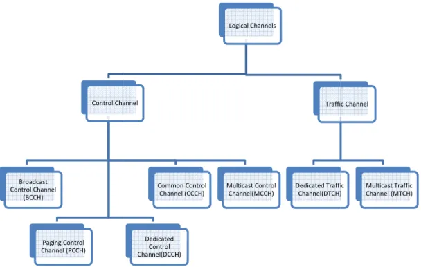
Figure 20. Logical channels in LTE. After [28]. Logical Channels Control Channel Common Control Channel (CCCH) Dedicated Control Channel(DCCH) Multicast Control Channel(MCCH) Traffic Channel Dedicated Traffic Channel(DTCH)
The MAC layer is mainly responsible for managing the mapping of logical and the multiplexing and de-multiplexing logical and transport and Figure 21, respectively. sport channels for the downlink for the uplink are displayed in Figure 23. The for uplink is UP-SCH, as functions performed by MAC are the (HARQ) for retransmission function, scheduling handling between UEs by means of dynamic ne UE, logical channel
Traffic Channel
Dedicated Traffic Channel(DTCH)
Multicast Traffic Channel (MTCH)
![Figure 5. Frequency-time representation of an OFDM signal. From [20].](https://thumb-us.123doks.com/thumbv2/123dok_us/10175101.2919821/40.892.149.749.740.974/figure-frequency-time-representation-ofdm-signal.webp)
![Figure 7. Contrast between transmission schemes of OFDM and OFDMA. From [18].](https://thumb-us.123doks.com/thumbv2/123dok_us/10175101.2919821/42.892.131.768.444.737/figure-contrast-transmission-schemes-ofdm-ofdma.webp)
![Figure 8. SC-FDMA signal generation chain. From [18].](https://thumb-us.123doks.com/thumbv2/123dok_us/10175101.2919821/43.892.176.743.577.740/figure-sc-fdma-signal-generation-chain.webp)
![Figure 13. LTE frame structure type 2 (5 ms switch point periodicity). From [22].](https://thumb-us.123doks.com/thumbv2/123dok_us/10175101.2919821/47.892.190.719.242.457/figure-lte-frame-structure-type-switch-point-periodicity.webp)
![Figure 15. High level architecture of LTE. After [25].](https://thumb-us.123doks.com/thumbv2/123dok_us/10175101.2919821/50.892.144.725.472.990/figure-high-level-architecture-lte.webp)
![Figure 16. Functional split between the E-UTRAN and EPC. From [26].](https://thumb-us.123doks.com/thumbv2/123dok_us/10175101.2919821/51.892.154.761.304.722/figure-functional-split-e-utran-epc.webp)
![Figure 17. User plane protocol stack. After [26].](https://thumb-us.123doks.com/thumbv2/123dok_us/10175101.2919821/52.892.238.681.745.1041/figure-user-plane-protocol-stack-after.webp)
![Figure 19. Transmission of data in LTE downlink in time domain. From [27].](https://thumb-us.123doks.com/thumbv2/123dok_us/10175101.2919821/53.892.177.674.719.1029/figure-transmission-data-lte-downlink-time-domain.webp)