Scalable and Reliable Middlebox
Deployment
by
Milad Ghaznavi
A thesis
presented to the University of Waterloo in fulfillment of the
thesis requirement for the degree of Doctor of Philosophy
in
Computer Science
Waterloo, Ontario, Canada, 2020
Examining Committee Membership
The following served on the Examining Committee for this thesis. The decision of the Examining Committee is by majority vote.
External Examiner: Stefan Schmid Professor
Department of Computer Science University of Vienna
Supervisor: Raouf Boutaba
Professor
David R. Cheriton School of Computer Science University of Waterloo
Internal Member: Bernard Wong Associate Professor
David R. Cheriton School of Computer Science University of Waterloo
Internal Member: Ali José Mashtizadeh Assistant Professor
David R. Cheriton School of Computer Science University of Waterloo
Internal-External Member: Wojciech Golab Associate Professor
Department of Electrical and Computer Engineering University of Waterloo
Author’s Declaration
This thesis consists of material all of which I authored or co-authored: see Statement of Contribu-tions included in the thesis. This is a true copy of the thesis, including any required final revisions, as accepted by my examiners.
Statement of Contributions
This dissertation includes first authored peer reviewed materials that have appeared in conference and journal proceedings published by the Institute of Electrical and Electronics Engineers (IEEE) and Association for Computing Machinery (ACM).
The ACM’s policy on reuse of published materials in a dissertation is as follows:
“Authors can include partial or complete papers of their own (and no fee is expected) in a dissertation as long as citations and DOI pointers to the Versions of Record in the ACM Digital Library are included.”
The following list serves as a declaration of the Versions of Record for works included in this dissertation:
Portions of Chapter 2:
Milad Ghaznavi, Nashid Shahriar, Shahin Kamali, Reaz Ahmed, and Raouf Boutaba. Distributed service function chaining.IEEE Journal on Selected Areas in Communications, 35(11):2479–2489, November 2017.https://doi.org/10.1109/JSAC.2017.2760178
Portions of Chapter 3: Milad Ghaznavi, Ali Jose Mashtizadeh, Bernard Wong, and Raouf Boutaba. Constellation: A high performance geo-distributed middlebox framework. Technical Report arXiv:2003.05111 [cs.NI], ArXiV, March 2020.https://arxiv.org/abs/2003. 05111
Portions of Chapter 4:
Milad Ghaznavi, Elaheh Jalalpour, Bernard Wong, Raouf Boutaba, and Ali Jose Mashtizadeh. Fault tolerant service function chaining. InProceedings of the 2020 ACM Conference on Special Interest Group on Data Communication, SIGCOMM ’20, New York, NY, USA, August 2020. Association for Computing Machinery (ACM).To appear
Abstract
Middleboxes are pervasive in modern computer networks providing functionalities beyond mere packet forwarding. Load balancers, intrusion detection systems, and network address translators are typical examples of middleboxes. Despite their benefits, middleboxes come with several challenges with respect to their scalability and reliability.
The goal of this thesis is to devise middlebox deployment solutions that are cost effective, scalable, and fault tolerant. The thesis includes three main contributions: First, distributed service function chaining with multiple instances of a middlebox deployed on different physical servers to optimize resource usage; Second, Constellation, a geo-distributed middlebox framework enabling a middlebox application to operate with high performance across wide area networks; Third, a fault tolerant service function chaining system.
Acknowledgements
I would like to express my special gratitude to my supervisor, Professor Raouf Boutaba, for his support throughout my doctoral studies. Raouf has been amazingly patient with me allowing me to mature as a researcher; he has been a wonderful source of knowledge and experience guiding me through my graduate career.
I extend my thanks to my examining committee, Professor Stefan Schmid, Professor Wojciech Golab, Professor Bernard Wong, and Professor Ali José Mashtizadeh, for reviewing my thesis and participating in my defense during the COVID 19 pandemic. I have been incredibly fortunate to have closely worked with and learned from Bernard and Ali.
I would thank my friends and colleagues, Benjamin Cassell, Shihab Rahman Chudhury, and Shahin Kamali for their collaboration and friendship, in particular my friend, Ali Abedi. Big thanks to Elaheh Jalalpour, my colleague and good friend, for all joyful and stressful moments we experienced throughout our graduate studies.
My deepest appreciation goes to my parents, Touran and Nosratollah, for everything they have done for me; my father will be forever in my heart. I am immensely grateful to my bothers and sisters for their unconditional love, support, and confidence; special thanks to my brother, Mahmoud, for his support over the past few years in Canada.
Table of Contents
List of Figures xii
List of Tables xiv
1 Introduction 1
1.1 Distributed Service Function Chaining . . . 2
1.2 Constellation: A Geo-Distributed Middlebox Framework . . . 3
1.3 Fault Tolerant Service Function Chaining . . . 4
1.4 Dissertation Plan . . . 4
2 Distributed Service Function Chaining 5 2.1 Challenges. . . 7
2.1.1 System Implementation Challenges . . . 7
2.1.2 Optimization Challenges . . . 9
2.2 Distributed Service Function Chaining . . . 11
2.2.1 Definitions . . . 11
2.2.2 Mathematical Model: . . . 11
2.3 NP Hardness of Distributed Service Function Chaining . . . 14
2.4 Kariz: Heuristic Solution . . . 16
2.4.1 Route and Middlebox Instances . . . 18
2.4.3 Update Layers . . . 22
2.4.4 Time Complexity Analysis . . . 23
2.5 Evaluation . . . 24
2.5.1 Experimental Setup and Methodology . . . 24
2.5.2 Acceptance Ratio . . . 25
2.5.3 Resource Utilization . . . 27
2.5.4 Operational Costs . . . 27
2.6 Related Work . . . 30
2.7 Conclusion and Future Work . . . 31
3 Constellation: A Geo-Distributed Middlebox Framework 32 3.1 Background and Motivation . . . 34
3.1.1 Middlebox State . . . 35
3.1.2 Recent Work: State Management for LAN . . . 35
3.1.3 Geo-distributed Middleboxes. . . 36
3.2 Design Overview . . . 38
3.2.1 Study of Common Middleboxes . . . 38
3.2.2 Constellation Design Choices . . . 40
3.3 Constellation Middlebox Framework . . . 41
3.3.1 State Objects . . . 42
3.3.2 Asynchronous State Replication . . . 44
3.3.3 Dynamic Scaling . . . 47
3.4 Implementation and Experience . . . 48
3.4.1 Network Address Translator . . . 49
3.4.2 Artifacts of Asynchronous Replication. . . 49
3.5 Evaluation . . . 50
3.5.1 Experimental Setup and Methodology . . . 50
3.5.3 Performance in Normal Operation . . . 52 3.5.4 Dynamic Scaling . . . 57 3.5.5 Coalescing Benefits. . . 58 3.5.6 Inconsistency Artifacts . . . 58 3.5.7 Development Complexity . . . 59 3.6 Related Work . . . 61
3.7 Conclusion and Future Work . . . 62
4 Fault Tolerant Service Function Chaining 63 4.1 Background . . . 65
4.1.1 Challenges . . . 66
4.1.2 Limitations of Existing Approaches . . . 66
4.2 System Design Overview . . . 67
4.2.1 Requirements . . . 67
4.2.2 Design Choices . . . 68
4.3 FTC for a Single Middlebox . . . 69
4.3.1 Middlebox State Replication . . . 69
4.3.2 Concurrent Packet Processing . . . 72
4.3.3 Concurrent State Replication . . . 73
4.4 FTC for a Chain . . . 75
4.4.1 Normal Operation of Protocol . . . 76
4.4.2 Failure Recovery . . . 78
4.5 Implementation . . . 79
4.6 Evaluation . . . 79
4.6.1 Experimental Setup and Methodology . . . 79
4.6.2 Micro-benchmark . . . 81
4.6.3 Fault Tolerant Middleboxes . . . 83
4.6.5 Failure Recovery . . . 88 4.7 Related Work . . . 90 4.8 Conclusion and Future Work . . . 91
5 Conclusions 92
5.1 Thesis Summary . . . 92 5.2 Future Research Directions . . . 93
List of Figures
2.1 Distributed Deployment of a Chain . . . 10
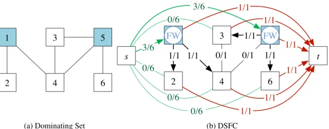
2.2 To send a flow of sizennn= 6fromstot, a flow of size 3 is sent to nodes 1 and 5. These nodes then send a flow of size 1 to any node that they dominate. Firewalls are placed at dominating nodes 1 and 5. . . 15
2.3 Layers . . . 17
2.4 Routing as Single-Source Single-Sink MCFP . . . 19
2.5 Actions . . . 21
2.6 Acceptance Ratio . . . 26
2.7 Resource Utilization Comparison. . . 28
2.8 Operational Costs . . . 29
3.1 The architecture of an NFV environment . . . 34
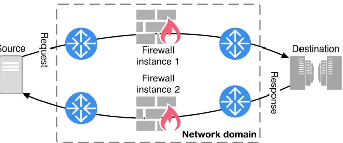
3.2 Firewall and asymmetric routing. The second accepts the response traffic because the instances share state. . . 37
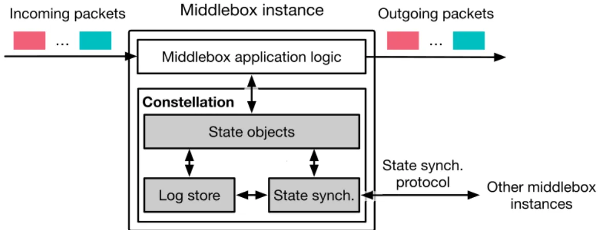
3.3 Constellation’s design components . . . 41
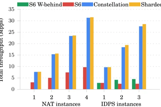
3.4 Total throughput of middleboxes: Compared to linear scaling, Constellation is within 2–4% for NAT and 1–5% for IDPS. . . 53
3.5 Total throughput of two NAT instances in WAN. Constellation’s throughput is largely independent of WAN latency, but synchronous accesses to remote state slow down S6’s throughput by6×to32×going from 5 to 100 ms latency. . . 54
3.6 End-to-end Latency of the first instance of 2 NAT instances deployed in our LAN. Constellation’s average and 99 percentile latency remain steady under sustainable loads. Constellation’s latency increases by approaching to its saturation point. . . 56
3.7 Throughput of the first instance of 2 NAT instances in a scale-out event. This instance experiences a sub-millisecond throughput disruption duringfork. The
throughput becomes unsteady for few milliseconds during state transmission. . . 57
3.8 Coalescing benefits. IXP-1 and IXP-2 are two traces of an internet exchange point [108,109]. We observe more compression for IXP-1 because IXP-1 has fewer distinct flows compared to IXP-2. Because the counting bloom filter operates on a smaller flow key space, more state updates can be coalesced for IXP-1. 59 3.9 Histogram shows the number of packets leaked beyond the target threshold for Constellation’s IDPS. . . 60
4.1 Service function chain model in NFV . . . 65
4.2 Normal operation for a single middlebox . . . 70
4.3 Data dependency vectors. The head and the replica run two threads and maintain a dependency vector for three state partitions. . . 74
4.4 Normal operation: chain ofnmiddleboxes. . . 76
4.5 Throughput vs. state size . . . 81
4.6 Throughput ofMonitor . . . 82
4.7 Throughput ofMazuNAT . . . 83
4.8 Latency of middleboxes. . . 84
4.9 Throughput vs. chain length . . . 86
4.10 Latency vs. chain length . . . 87
4.11 Ch-3per packet latency . . . 88
4.12 Replication factor . . . 89
List of Tables
2.1 Middleboxes . . . 9 2.2 Off-the-shelf middleboxes . . . 24 3.1 Time to access state in different locations: The throughput of remote state across
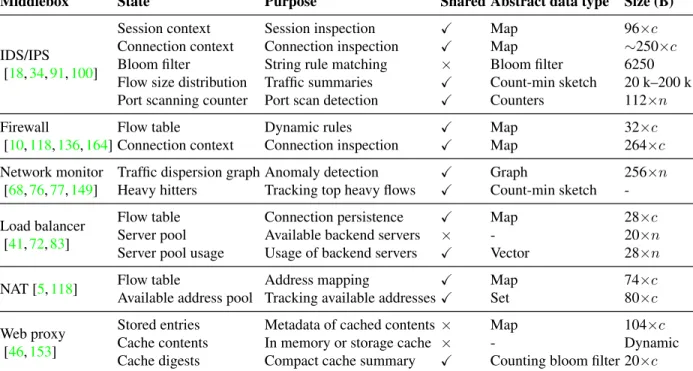
a wide area network can be as low as 10 to 100 accesses per second. . . 37 3.2 Examples of common middleboxes: A list of common middlebox applications
are shown. For “Size (B)”, c and n are respectively the number of connec-tions/sessions and hosts/servers. Note that we provide a representative set of state for each middlebox, and the they are not exhaustive. Moreover, for each middlebox application, we list the state of multiple implementations, and an implementation does not necessarily include all the presented state. . . 38 3.3 Throughput of a pass-through middlebox in Mpps. S6 is built on DPDK, while
Constellation uses DPDK+Click that adds overhead to the toolkit baseline. Refer-ence adds the overhead of finding which node owns a state object. We measure the read and write costs separately and together. . . 51 3.4 NAT average latency. Constellation’s latency remains constant going from 2 to
3 NAT instances. Its latency increase going from 1 to 2 is due to the scheduling overhead of Click. . . 55 4.1 Experimental middleboxes and chains . . . 81
Chapter 1
Introduction
Middleboxes, such as firewalls, WAN optimizers, and network address translators are pervasive in computer networks. They enable modern networks to perform advanced functionalities that are beyond packet forwarding. For example, they protect against threats by filtering malicious traffic, improve network performance by optimizing resource usage, and mitigate scarcity of IPv4 addresses [131,142,147,167].
Deploying and operating middleboxes have been hindered by employing hardware middlebox appliances. A small number of vendors customize hardware and software of these appliances for specific functionalities. At the beginning of their service life time, resources of these appliances are under utilized, as they are over provisioned for peak loads [142]. On the other hand, fixed hardware resources become obsolete quickly and unable to handle average network loads. Providing fault tolerance, which is essential for middlebox applications, can be also burdensome for middlebox hardware appliances. A backup infrastructure requires purchasing and configuring a duplicate set of hardware appliances [145]
Network Function Virtualization (NFV) [44] aims to accelerate and facilitate innovations for middleboxes by transforming the way they are provided. NFV decouples middlebox functionalities from hardware by creating software instances, for example virtual machines or containers that run on commodity servers. This allows network operators to install and remove middlebox instances on demand in response to traffic loads. Network operators can also devise more general and flexible mechanisms to provide fault tolerance for a diverse set of middlebox applications and deployments.
NFV can revolutionize the networking industry; however, its realization in practice is chal-lenging. It still has to face several theoretical and system design challenges on its path to success.
This dissertation presents three contributions aiming to bridge the gap between NFV promises and practical realization:
• Cost reduction: Distributed service function chaining optimizes the cost of deploying middleboxes in cloud infrastructures. Middleboxes are commonly chained together in an ordered sequence, e.g., firewall→IDS→proxy, to meet high level service requirements. This middlebox deployment is called aservice function chain[130,131]. Our approach places middlebox instances of a chain distributedly where multiple instances of a single middlebox can be deployed in different servers. Compared to prior approaches that do not allow such a distributed deployment, our approach decouples the throughput of a middlebox from the underlying hardware while utilizing resources more efficiently.
• Dynamic scaling: Constellation is a framework for a geo-distributed deployment of mid-dleboxes. Constellation allows network operators to dynamically scale the number of middlebox instances that cooperatively process traffic over a wide area network. Using loosely coupled replication, Constellation enables middlebox instances to be deployed across a geo-distributed sites with high latency links, while prior middlebox frameworks are designed and optimized only for deployments in local area networks with low latency. • Fault tolerance: Fault Tolerant service function Chaining (FTC) is a system that provides fault tolerance to an entire chain of middleboxes. FTC’s design takes advantage of the structure of a service function chain to provide fault tolerance. This design allows FTC to support higher performance than can be achieved by prior systems; their design comes with high performance overhead because they consider individual middleboxes as independent fault tolerant units that together form a fault tolerant chain.
These contributions enable network operators to support middlebox deployments that are cost efficient, scalable, and fault tolerant. Next, we briefly describe each contribution.
1.1
Distributed Service Function Chaining
The deployment of a service function chain involves selecting and instantiating a number of middlebox instances, placing these instances, and routing traffic through them. In the current optimization models of a chain deployment, instances of the same function are assumed to be identical, while typical service providers offer middleboxes with heterogeneous throughput and resource configurations. The instances of a middlebox are installed in a single server which limits
a chain to the throughput of a few instances that can be installed in a single physical machine. Furthermore, the selection, placement, and routing problems are solved in isolation.
We present distributed service function chaining that coordinates these operations, places instances of a middlebox distributedly, and selects appropriate instances from typical middlebox offerings. This deployment uses network resources efficiently and decouples a chain’s throughput from that of physical servers. Our specific contributions in this work are:
• Providing a mathematical model for the problem of distributed service function chaining and proving its NP hardness.
• ProposingKariz, a local search heuristic that solves this problem for large networks. We implemented Kariz and evaluated its performance. In accepting requests for deploying middlebox chains, our results show that Kariz achieves an acceptance ratio of 76–100% at an extra cost of at most 24% compared with the optimal solution.
1.2
Constellation: A Geo-Distributed Middlebox Framework
Middleboxes are increasingly deployed across geographically distributed data centers. The instances of a middlebox distributed across different sites maintain and share state information to cooperatively process traffic. In these scenarios, the WAN latency between different sites can significantly impact the middlebox performance. The deployment across such infrastructures can even become impractical due to the high cost of remote state accesses over wide area networks.
Constellationis a framework for the geo-distributed deployment of middleboxes. Constellation uses asynchronous state replication of specialized state objects to achieve high performance and scalability. Our framework has the following key attributes:
• Highly scalable and performant state sharing using asynchronous state replication.
• Providing convergent state objects that can be independently updated across different instances.
• Building an efficient and reliable multicast state replication layer that synchronizes conver-gent state objects using their own properties.
Our evaluation of Constellation shows that compared to the state of art [173], Constellation improves the throughput by a factor of 96 over wide area networks.
1.3
Fault Tolerant Service Function Chaining
Tolerating failures when they occur along chains is imperative to the availability and reliability of enterprise applications. Service outages due to chain failures severely impact customers and cause significant financial losses. Making a chain fault tolerant is challenging since, in the case of failures, the state of faulty middleboxes must be correctly and quickly recovered while providing high throughput and low latency.
We present FTC, a novel system design and protocol for fault tolerant service function chaining. FTC provides strong consistency with up tof middlebox failures for chains of length
f+ 1or longer without requiring dedicated replica nodes. In FTC, state updates caused by packet processing at a middlebox are collected, piggybacked into the packet, and sent along the chain to be replicated. FTC makes the following specific contributions:
• Extending the replication protocol in [163] to support a chain of middleboxes.
• Improving the usability of multicore middleboxes by introducing transactional packet processing where a middlebox thread processes each packet in a transaction.
• Improving the replication performance using data dependency vectors that track depen-dencies between packet transactions with higher flexibility compared to prior thread-based techniques.
We implemented and evaluated FTC. Our results for a chain of 2 to 5 middleboxes show that FTC improves throughput by 2×to 3.5×compared with the state-of-the-art [146] with lower latency per middlebox.
1.4
Dissertation Plan
This dissertation proceeds as follows to detail our contributions. In Chapter 2, we present distributed service function chaining. We discuss Constellation in Chapter3. Next in Chapter4, we present fault tolerant service function chaining. Finally, we discuss the future of middlebox deployments and conclude this dissertation in Chapter5.
Chapter 2
Distributed Service Function Chaining
A service-function chain, or simply achain, is an ordered sequence of middleboxes composing a service [131]. For example in a typical data-center network, traffic from a server passes through an IDS, a firewall, and a NAT before reaching to the Internet [167]. Until recently, middleboxes have been vertically integrated in dedicated hardware middleboxes, i.e., a chain of pricey hardware middleboxes are provisioned to provide throughput for peak-load, and traffic must be routed through fixed locations in which these middleboxes are placed [130].
By decoupling network functions from underlying hardware, NFV implements middleboxes as software appliances – also known asvirtual network functions– that run on commodity servers. In this way, a chain of inexpensive middlebox instances provide the same packet-processing functions at a desired throughput, and we can route traffic through appropriate locations in which these instances are dynamically placed. Such a deployment reduces capital and operational costs and optimizes network operations.
A chain deployment involvesselectingand instantiating a number of middlebox instances, placingthese instances, androuting traffic through them. An optimal chain deployment coor-dinatesthe selection, placement, and routing to minimize resources allocated while satisfies the resource capacity and location constraints. Prior middlebox chaining models have several limitations as follows.
Gaps in Selection: Most of the optimization models [6,11,171] do not consider the typical middlebox offerings and assume that instances of the same middlebox are identical in their resource consumption and throughput. Service providers offer middlebox instances with different configurations to provide predictable quality of service. For example, HP offers virtual IPSec [73] that provides throughputs of 268, 580, and 926 Mbps assuming respectively 1, 4, and 8 CPU cores.
Similarly, Riverbed offers WAN-optimizers [137] with throughputs of 10 and 50 Mbps given respectively 2 and 4 CPU cores. Note that the correlation between the throughput and resource consumption is not necessarily linear. In practice, predicting the performance of middlebox software instances is not trivial [8,39,40].
Gaps in Placement and Routing: To process a traffic flow, some models use a single physical-machine to place the instances of a same middlebox [6,11,93,104,112] or even all middleboxes of a chain [142]. However, doing so severely limits throughput of a middlebox and a chain to a few instances that can be instantiated in a physical-machine. The throughput of these instances might not be sufficient to process the total traffic routed through them, and this problem is exacerbated by the fact that traffic volume through middleboxes has an increasing trend [75,170].
Gaps in Coordination: A middlebox instance cannot be selected if there is not sufficient resources to place its instances. Further, it is impractical to place an instance in a given location when adequate bandwidth is not available to route traffic from/to the location. To achieve an optimal deployment of service chains, selection, placement, and routing must be performed in a coordinated manner; otherwise, the deployment results in sub-optimal utilization of network resources and quality of service. Most of existing solutions solve the placement and routing in isolation [47,56,130,175]. There are few solutions [11,112] that coordinate the placement and routing; however, they treat the selection of middlebox instances separately.
To fill the above gaps, we present distributed service function chaining (DSFC). For each middlebox of a chain, DSFC selects from provided middlebox offerings and determines the appropriate number of instances to be placed. DSFC places these instances in a way that instances of a same middlebox can be installed distributedly in multiple machines. Such a placement decouples a chain’s throughput from physical-machines. Further, DSFC, utilizing the global knowledge of the network, routes traffic and distributes the load among the middleboxes instances. DSFC coordinates selection, placement, and routing operations in such a way that network resources are utilized more efficiently.
Specifically, our contributions in this chapter are:
• We model and solve DSFC using mixed integer programming (MIP), and prove its NP-Hardness.
• For larger networks, we propose Kariz, a local search heuristic that employs a tuning parameter to balance the speed-accuracy trade-off;
• We perform extensive simulations to evaluate Kariz against the MIP implementation for various chain-lengths and throughput-demands. The results demonstrate that Kariz achieves the competitive acceptance ratio of 76-100% at an extra cost of less than 24%, in comparison to the MIP implementation.
2.1
Challenges
A chain specifies that the traffic originating from asource, is processed by an ordered sequence of middleboxes, and finally is delivered to atarget. To deploy a chain distributedly, several system and optimization challenges have to be addressed.
2.1.1
System Implementation Challenges
Middleboxes often operate on data-packets at aflowgranularity and maintainstate information on the flows and sessions they process [151,166]. State information consists of configuration and statistical data, and differs from one middlebox to another. If a middlebox is replaced with multiple software instances, the functionality should not change, and these instances must act in concert. Further, the traffic processed by a single middlebox, should now be processed by multiple software instances. Thus,consistent state distributionandconsistent traffic distributionamong the software instances are essential.
Consistent State Distribution
Deployment of multiple software instances to provide a middlebox requires distribution of the state information. Hence, we need tomodelthe state information anddistributeit among the middlebox instances consistently. The state information can be classified asinternalorexternal. The internal state is stored and used only by a single instance, while the external state is distributed and shared across multiple instances.
Since the state information is stored in a key-value store [80,151], data structures like distributed hash-tables and technologies likeremote direct memory access(RDMA) can fulfill this challenge efficiently. Moreover, it might be required to modify the middleboxes to cope with the defined model. There are abstraction models and system implementations that address this challenge. Rajagopalan et al. [134] introduce a system-level abstraction called Split/Merge that stores the internal state exclusively inside each middlebox instance, while the external state is
distributed and accessible by other instances. As a proof of concept, they implemented FreeFlow as a Split/Merge system, and ported Bro IDS [123] inside it. Further, they analyzed and confirmed the compatibility of two other middleboxes, i.e., application delivery controller and stateful NAT64. In addition, Joseph and Stoica [80] provide a model to describe different middleboxes. As concrete examples, firewall, NAT and layer4 and layer 7 load-balancer are described using the proposed model. Further, Qazi et al. [57] and OpenNF [58] introduce a unified framework to manage state information.
Consistent Traffic Distribution
Replacing a single middlebox with multiple software instances requiressplittinganddistributing the traffic load among these instances. Per-flow traffic splitting distributes the traffic in the granularity of flows, and packets of a flow have to be routed along the same path.
Split/Merge [134] utilizes a similar approach. However, this approach does not support accurate load-distribution and is not always applicable. For instance, if the load of a flow is higher than the throughput of an assigned middlebox instance, that instance cannot handle the load and we have to split the traffic into a smaller granularity.
Flowlet switching[2,148] can be leveraged to split the traffic into a finer granularity. A flowlet is a “burst of packets from the same flow followed by an idle interval” [148]. If the interval between two flowlets is greater than the maximum delay difference between parallel paths, the second flowlet – and consequently following flowlets – can be sent through different paths. Thus, a single flow can be split into multiple paths without packet-reordering.
Furthermore, accurate load balancing is achieved using short flowlet intervals ([50,100]ms) [148]. Specifically, flowlets are abundant in data-center networks since the latency is very low and the traffic is intensively bursty [82]. In addition to these distributed methods, the central schemes leveraging SDN and OpenFlow capabilities [101] can also be used. For instance,group tables[51] can be used to split and balance the traffic.
We have shown the feasibility of distributed deployment of middlebox instances to provide a middlebox and distributing traffic among these instances. Next, we state the assumptions that ground our optimization model:
• The state information of a middlebox can be consistently distributed among multiple middlebox instances. This assumption holds for the state information of a single flow. • The traffic can be consistently distributed into multiple paths among multiple middlebox
Middlebox Instance type Throughput CPU demand Memory demand
IDS IDS1 50 Mbps 1 core 24 GB
IDS2 80 Mbps 1 core 32 GB
Firewall FW1 100 Mbps 1 core 1.75 GB
FW2 200 Mbps 2 core 3.50 GB
Table 2.1: Middleboxes
2.1.2
Optimization Challenges
The optimization challenge is in computing an optimal allocation of host and bandwidth resources to a chain. Each middlebox in a chain is replaced with a number of software instances providing the requested throughput. These instances are placed in a set of chosen hosts. In addition, the traffic is split and routed among the instances. Thus, certain decisions have to be made optimally:number of middlebox instances(selection),placementof these instances, androuting the trafficthrough the placed instances. These decisions are inter-dependent and must be made in a coordinated manner.
Figure2.1shows a chain deployment. The network of Figure2.1aincludes 6 hosts, each with an 8-core CPU and 64 GB residual memory. For simplicity, switches are not shown, and the presented paths are disjoint in this example. All paths have 130 Mbps available bandwidth.
The chain of Figure2.1bincludes 2 middleboxes with 210 Mbps throughput: an IDS and a firewall (FW). The flow comes from the hostA, the source, is processed by IDS and FW, and then sent to hostF, the target. As listed in Table2.1, there are 4 different instances for IDS and FW.
Figure2.1c depicts the chain deployed in the network, and Figure2.1dshows the logical representation of this deployment: with 3 instances for IDS (1×IDS1+ 2×IDS2) and 2 instances for FW (1×FW1 + 1×FW2). The IDS instances are installed in hostsB and D. The flow splits, and 80 Mbps and 130 Mbps are routed from the source to hostsBandD, respectively. FW instances are installed in hostsB andE. In hostB, the flow after being processed by IDS2is sent to FW1. IDS1and IDS2forward the flow to hostCin which instance FW2 is placed. Finally, the flow from the FW instances is sent to the target. Note that it is possible to place the middlebox instances in the source and target if sufficient host resources are available.
A
D
B
E
C
F
130
130
130
130
130
130
(a) NetworkA
IDS
FW
F
210
210
210
(b) ChainA
C
F
IDS 2 IDS 2 IDS 1 FW 1 FW 2 80 50+80 80 50+80 80 130 80 (c) Deployed in NetworkF
A
IDS 2 IDS 1 IDS 2 FW2 FW 1 50 80 80 80 80 50 80 130 (d) Logical Representation Figure 2.1: Distributed Deployment of a Chain2.2
Distributed Service Function Chaining
With the assumptions and challenges established, we now introduce the formal definitions and the mathematical model.
2.2.1
Definitions
Physical Resources: R ={CPU, memory, storage, . . .}is a set of available physical resources. Network: GraphG= (N, E)is the substrate network, whereN andE are substrate nodes and links, respectively. cmr ∈ R+ is the residual capacity of nodem for resourcer ∈ R. SetEm denotes incident links on nodem. Moreover,mn∈E is the link between nodem∈N and node
n∈N and has a residual bandwidth capacity ofcmn ∈R+.
Chain: Symbols with over-line are for chain definitions. Forwarding graphG= (N , A)denotes a chain. N includes middleboxesV ⊂N, and two endpointssandt. Traffic flow coming from
s∈N is processed by middleboxes in the chain, and is forwarded tot ∈N. Respectively,sandt
are thesourceandtargetof the traffic. The corresponding substrate nodes for source and target are respectivelys ∈N andt ∈N.
Middlebox v = f(u) follows middlebox u. We define ring uv ∈ A as 2 consecutive middleboxesuandv, wherev =f(u). We assume thatugenerates traffic typeuandv consumes this traffic type. Each ringuvhas thethroughput demandbdenoting integer traffic volume flow generated or consumed by the ring nodes.
Middlebox instances: V denotes a set of middlebox instances. An instanceu∈V has through-putqu ∈R+showing the maximum traffic thatucan process. d
ur ∈R+is the demand ofufor resourcer. These demands include the overhead of accessing distributed state information. Fors
andt, we assume that there are instancesusandut, respectively. These instances have throughput
band no demand for any resource. Finally, instances of middlebox typeuare identified byVu.
2.2.2
Mathematical Model:
Variablexumn ∈ R is the traffic volume of type u ∈ N /{t} on substrate link mn. Targett is excluded since it only consumes traffic; thus, no traffic of this type exists in the network. Variable
ymu ∈ Z is the number of instancesu in substrate nodem. Instances ofVu installed in node
mprovide throughput of typeu. Variablezmu ∈ Rdenotes the allocated throughput of these instances.
A solution for the problem is shown by a tuple of allocation vectors (X, Y, Z), defined as follows. Let vectorXu ={xumn :∀mn ∈ E}be allocated bandwidth of links to traffic typeu, andX =S
u∈N /{t}Xu. IfYu ={ymu:∀m∈N,∀u∈Vu}identifies the instances for middlebox typeu, letY =S
u∈NYu. Finally,Zu ={zmu : ∀m ∈N}denotes the allocated throughput of typeuin every node, andZ =S
u∈NZu.
Node Capacity Constraint: Equation2.1ensures that instances are placed with respect to the substrate nodes capacities.
∀m∈N :∀r∈R:X
u∈V
ymudur ≤cmr (2.1)
Location Constraint: Equalities in Equation2.2ensure that an instance ofusand an instance ofutare placed only ins∈N andt ∈N, respectively.
ysus = 1, X m∈N/{s} ymus = 0 ytut = 1, X m∈N/{t} ymut = 0 (2.2)
Substrate Link Capacity Constraint: Equation2.3makes sure that the capacities of substrate links are not violated.
∀mn∈E, m < n:X
u∈N
(xumn+xunm)≤cmn (2.3) Throughput Constraint: Equation 2.4ensures that the aggregate throughput capacity of in-stances of typeuplaced in substrate nodemis more than allocated throughputzmu.
∀m∈N :∀u∈N : X
u∈Vu
Throughput Demand Constraint: Equation2.5guarantees that for each middleboxu, through-putbis allocated by instancesVu.
∀u∈N : X
m∈N
zmu=b (2.5)
Flow Conservation Constraint: Equation2.6is a modified version of the flow-conservation constraint [161]. Let us say that in nodem ∈N, instances of middlebox typesuandv =f(u)
are installed. Therefore, instances ofVvlocally process a volume of traffic typeugenerated by instances ofVu. This volume iszmv. Unprocessed traffic volume should exit the nodem. This constraint ensures this phenomenon.
∀m ∈N :∀u∈N /{t}:v =f(u) :
X
mn∈Em
xumn−xunm = zmu−zmv
(2.6)
Bandwidth Allocation Cost: Equation2.7is the bandwidth allocation cost. Coefficientβ ∈R+ identifies the relative importance of bandwidth resources. The communication overhead to access the distributed state information is negligible vs. the actual service traffic volume.
B(X) = β X
u∈N /{t}
X
mn∈E
xumn (2.7)
Host Resource Allocation Cost: Equation2.8is the cost of allocating host resources to place middlebox instances. Coefficientαr ∈R+is the relative importance of resourcer ∈R.
H(Y) = X
u∈V
X
r∈R
αrdurymu (2.8)
Objective Function: Equation2.9minimizes the aggregate cost of allocating host and band-width resources.
2.3
NP Hardness of Distributed Service Function Chaining
In this section, we prove that the Distributed Service Function Chaining (DSFC) problem is NP hard. We use areduction from the NP hardminimum dominating setproblem. Our reduction technique is of independent interest and can be potentially applied to analyze the complexity of other problems related to service function chaining.
A dominating set of a graph is a set of nodes so that each node is either a member or adjacent to at least a member of this set. The goal is to find a dominating set with minimum size.
Given a graphGGGwithnnnnodes as an instance of the dominating set problem, we create an instance of DSFC and prove that there is a dominating set of sizekkkif and only if there is a solution of cost3nnn+kkkin the DSFC instance.
Recall from Section2.2.1, an instance of DSFC is defined with resources, a network, a service chain, and middleboxes. In our reduced instance, CPU is the only host resource. We define the network to be the same asGGGwith two extra nodessandt. These two nodes are connected to all nodes ofGGG. Nodessandthave 1 CPU core, and others have 2 CPU cores. Incident links ons
have the capacitynnn, and the capacity of other links is 1. The chain is defined ass →FW →t. Endpointssand trespectively correspond to sourcesand targettin the network, and FW is a firewall SF. Moreover, there is a single firewall instance demanding 2 CPU cores and providing throughput capacitynnn. On this instance of DSFC, the goal is to install firewall instances to process aflow of sizennn froms tot. Note that these middleboxes require 2 CPU cores and cannot be placed insort. Here, by ‘flow’, we mean the traffic that is to be sent fromstot. We defineαr (r=CPU) andβto be 1, hence the total cost of DSFC is the total number of allocated CPU cores (resource cost) and bandwidth. Figure2.2depicts this reduction. Clearly, the DSFC instance can be constructed in polynomial time from the dominating set instance.
To prove the hardness, we show that there is a dominating set of sizekkkif and only if there is a solution for the DSFC instance with cost3nnn+kkk. We start with the easy direction:
Lemma 1. If there is a solution of sizekkkfor the dominating set problem, then there is a solution of cost3nnn+kkkfor the DSFC problem.
Proof. Letvvv1, . . . , vvvkkk denote the nodes in the dominating set, andaaaiii (1 ≤ iii ≤ kkk) denote the number of nodesvvviii dominates. If a node is dominated by more than one node, we count it only once (arbitrary assign it to one node in the dominating set). Note that we haveP
iiiaaaiii =nnn−kkk.
In the DSFC instance, we send a flow of sizeaaaiii+ 1 fromsto anyvvviii. Doing so results in bandwidth cost ofnnn. We also send a flow of size1fromvvviii to any of the nodes that it dominates; this requires a bandwidth ofaaaiiiforvvviiiand in total bandwidth ofnnn−kkkfor all dominating nodes.
1 3
6 5
4 2
(a) Dominating Set
1
3
6
5
4
2
s
t
3/6
0/6
3/6
0/6
0/6
1/1
1/1
1/1
1/1
0/6
1/1
1/1
1/1
1/1
0/1
0/1
1/1
1/1
FW
FW
(b) DSFCFigure 2.2: To send a flow of sizennn = 6fromsto t, a flow of size 3 is sent to nodes 1 and 5. These nodes then send a flow of size 1 to any node that they dominate. Firewalls are placed at dominating nodes 1 and 5.
Finally, we send a flow of size1from all nodes (excepts) to t. This results in bandwidth cost ofnnn(see Figure2.2b). We install a FW for the service chain in each node in the dominating set, resulting in resource cost of2kkk. In total, the cost isnnn+ (nnn−kkk) +nnn+ 2kkk= 3nnn+kkk.
To prove the other side of the reduction, we start with Lemma2.
Lemma 2. Given a solution of the DSFC problem with costccc, one can achieve a solution of cost no more thancccin polynomial time, for which the following properties for each node other than
s, thold: (1) the total inflow received through nodes other than sis at most 1; (2) the inflow is throughs or a node that receives inflow throughs; moreover, (3) FWs are placed at nodes receiving some flow directly froms; (4) each node receives either all or none of its inflow froms. Proof. We modify the solution to satisfy properties (1)-(4) in the same order without affecting previously satisfied properties. In this process, the cost of the solution is never increased. To satisfy (1), assume there is nodeuuuwith inflowxxx >1from node(s) other thans. This assumption implies a bandwidth cost of at least2xxxfor the flow passing at least another node betweensanduuu. In the new solution, we remove this flow and send a flow of sizexxxfromstouuuand place a FW at
u
uu. Doing so gives a bandwidth cost ofxxxand resource cost of2. The increase in cost is no more thanxxx+ 2−2xxx≤0.
Property (2) follows directly from (1). To satisfy (3), note that by (1), the flow between nodes excludingsandtform a forest. Placing FWs only in the roots in the forest does not increase the
cost. For (4), assume a node receives an inflow ofxxxthroughsand an inflow of 1 through another node. By (3), there is a FW atuuu. In the new solution, we send a flow ofxxx+ 1fromstouuuand remove the flow from the other node.
We use Lemma2to prove the other side of the reduction:
Lemma 3. If there is a solution of cost3nnn+kkkfor the DSFC problem, then there is a solution of sizekkkfor the dominating set problem.
Proof. First, we apply Lemma2to achieve a solution with the desired properties. We refer to the nodes that receive flow throughsascritical nodes. By property (4), a node receive all or none of its inflow froms. By (3), there is a FW located in critical nodes. By (1), each non-critical node has inflow of 1 and by (2), such node receives this inflow through a critical node. In other words, the graph formed by flows (excludingt), is a tree of diameter 2 rooted ats.
Letmmmdenote the number of critical nodes; the resource cost for FWs would be2×mmm. The bandwidth cost is3nnn−mmm: a cost ofnnn for the outflow ofs, another cost ofnnn for the inflow of
t, and an extra bandwidth cost ofnnn−mmm for the flow from critical nodes to non-critical ones (recall that the inflow of each non-critical node is 1). In conclusion, the total cost of the solution is3nnn+mmm, i.e., we have3nnn+mmm= 3nnn+kkk. In other words, the number of critical nodes iskkk. On the other hand, by (1) and (2) each non-critical node has an inflow of exactly 1 through a critical node. Hence, critical nodes form a dominating set of sizekkk.
From Lemmas1and3, Theorem1is direct.
Theorem 1. Finding the solution with minimum cost for DSFC is NP hard.
2.4
Kariz: Heuristic Solution
Before explaining our solution, we construct a visualization tool to simplify our description. Let us assume that eachu ∈ N is deployed in a layer. Each layer contains a set of nodes in which instances of a corresponding middlebox type can be installed. In other words, in the layer corresponding tou, we initially place a subset of nodes in which at least a middlebox instance
v ∈Vucan be instantiated. L(u)denotes this layer. Figure2.3cdepicts the layers for the chain of Figure2.3b. As shown in Figure2.3c,sandtare the only nodes present in layersL(s)andL(t), respectively. Further, nodes{s, m}and{n, t}are respectively included in layersL(u)andL(v)
because these nodes have sufficient resources to host instances of these middleboxes. Figure2.3d presents a sample solution for the chain of Figure2.3b.
s
n
m
t
(a) Networku
v
s
t
(b) Chains
L(s)
s
m
L(u)
n
t
L(v)
t
L(t)
(c) Layerss
L(s)
s
m
L(u)
n
L(v)
t
L(t)
(d) Sample Solution Figure 2.3: LayersInspired by [69,120], we develop a local search heuristic,Kariz, which routes traffic layer by layer. We introduce the process first, and then provide a detailed overview.
Kariz is shown in Algorithm1and works as follows. We first initialize layers as described above and set solution as empty (line 1). Starting from layerL(s)(line 2), iteratively route b
volume of traffic from layerS =L(u), thesource-layer, to the next layerT =L(v), thesink-layer (lines 3-11). After finding the optimal route between two layers (line 5), compute the number of instances ofVv by considering the allocated throughput (line 6). Add the solution of the sink-layer to the earlier solution (line 7). Improve the current solution (line 8), and update layers (line 9). Now, traffic has reached the sink-layer; consider this layer as new source-layer (line 10). Repeat this procedure if traffic has not reached the last layer yet, and there are nodes in the new source-layer (line 11).
Algorithm 1Kariz Algorithm
1: init-layers();(X, Y, Z)←(∅,∅,∅); 2: u←s;zss←b;ztt ←b;S ←L(s); 3: do 4: v ←f(u);T ←L(v); 5: Xv, Zv ←route(S, T, b); 6: Yv ←instances(Zv); 7: (X, Y, Z)←(X∪Xv, Y ∪Yv, Z∪Zv); 8: improve(X, Y, Z); 9: update-layers(); 10: u←v;S ←L(v); 11: while u6=tandS 6=∅;
Still to clarify are the traffic routing between two layers and the number of instances in the sink-layer, how the solution is improved, and how the layers are updated.
2.4.1
Route and Middlebox Instances
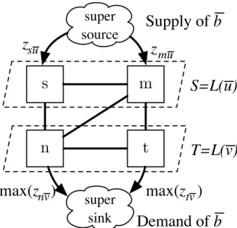
Procedureroute(.)in Algorithm1computes the route between two layers by solving the multi-source multi-sink minimum cost flow problem (MCFP) [63]. MCFP is the problem of routing a volume (sayb) of a commodity (in our case traffic of typeu) from multiple sources (say a source-layer) to multiple sinks (in our case a sink-layer). Any multi-source multi-sink MCFP can be modeled as a single-source single-sink MCFP that is solvable in polynomial time [63]. For
s
n
m
t
S=L(u)
T=L(v)
super
source
super
sink
max(
z
nvnv)
z
suDemand of
b
max(
z
nvtv)
z
muSupply of
b
Figure 2.4: Routing as Single-Source Single-Sink MCFP
our problem, this is achieved by representing the source- and sink-layers with imaginary nodes super-sourceandsuper-sink, respectively.
Figure2.4depicts this model for layersSandT in Figure2.3. The procedure is as follows. Add a super-source and connect it to every nodem∈S in the source-layer with a directed-link whose capacity iszmu. For the sink-layer, add a super-sink node and connect every noden∈T using a directed-link. The capacity of the directed-link connecting noden to the super-sink is the maximum throughputmax(znv)of the instances that can be installed in noden. There is no cost to sending the traffic via these links. As the result, the minimum cost route of traffic from super-source to super-sink gives the optimal routing between the two layers. Ifpdenotes the super-sink, the throughput allocation in eachn ∈L(v)isznv =xunp.
Finding the capacity of directed-links from the sink-layer to the super-sink is similar to the problem ofinstances(.). The former is finding the maximum throughputmax(znv)out of instances that can be installed in noden. The latter is finding the minimum allocation of resources to instances providing throughput of at leastznvin each noden ∈L(v).
In fact, these problems aredualand can be modeled as amultidimensional knapsack prob-lem[26]. Think of the node as an|R|-dimensional knapsack, eachdimensioncorresponding to a resourcer ∈ R. Theitemsto be packed are instances with theprofitsof their throughputs and weightsof their host resource demands.
Though this problem is known to be NP-Hard [26], since the resources of a single machine, especially the number of CPU cores, are limited, the problem size is small. Thus, we can solve it efficiently. Instead, as CPU cores are the most pricey and restricted resources, a feasible solution optimizing the number of allocated cores is a good optimum.
2.4.2
Solution Improvement Rounds
Routing between two layers focuses on the cost of traffic routing and does not consider the cost of host resource allocation. Doing so may lead to high host resource cost. Hence, we need to improve the solution.
Procedureimprove(.), as shown in Algorithm2, facilitates this: repeatedly search for some actionsto improve the solution (lines 2-8). If no such action is found, report the current solution (line 4-6). Otherwise, perform the action with the greatest drop in cost, the best admissible action (line 7), and continue with the adjusted solution. We define actions andadmissibilityin Section2.4.2and Section2.4.2, respectively.
Algorithm 2Procedureimprove(.)
1: procedureimprove(X,Y, Z)
2: loop
3: a←best-action(X, Y, Z);
4: ifnotadmissible(a)then
5: return(X, Y, Z);
6: end if
7: perf orm-action(X, Y, Z, a);
8: end loop
9: end procedure
Actions
An action is alocal transformationintended to reduce the cost of solution. Let(X0, Y0, Z0)be the modified solution after performing an action on a current solution(X, Y, Z). The cost difference before and after performing an action is regarded as theaction cost, as defined in Equation2.10. The best action has the lowest cost.
m
L(u)
L(v)
L(w)
p
n
…
…
…
…
z
nv+
𝛅
nv (a)add(n, L(v), δ)L(u)
m
L(v)
L(w)
p
n
…
…
…
…
z
nv+
𝛅
nvx
x
x
(b)open(n,{m}, L(v), δ) Figure 2.5: ActionsWe define the below actions variants of actions used by [120]:
• add(n, L(v), δ): Include noden ∈N inL(v)and allocate moreδ >0units of throughput in this node (znv ←znv+δ). Then, find the minimum cost routing from layerL(v)to the next and previous layers in the current solution, given allocated throughputs ofL(v)/{n}. The next and previous layers areL(w)andL(u)ifw =f(v)andv = f(u), respectively. Finally, tune the allocated throughput of nodesL(v). This action is shown in Figure2.5a. • open(n, M, L(v), δ): Add node n ∈ N into layer L(v), remove nodes M ⊆ L(v), and
allocate more δ > 0units of throughput in noden(znv ←znv+δ). Finally, reroute the traffic either received or originated in layerL(v). This action replaces a set of fragmented middlebox instances installed in different nodesM with instances collocated in one noden. This action makes sense only ifδ ≥P
m∈M(zmv). Figure2.5bdepicts an example of this action.
Traffic routing in the above actions is a bit different from routing inroute(.). The difference lies in routing two different traffic types. Considering each traffic type as a commodity, still this problem can be modelled it as a multi-commodity MCFP (real flows) that is solvable in polynomial time [45].
We also need to examine actions and select the best in polynomial time and ensure that the number of performed actions is not exponential. Particularly, we need to select the best action with sufficient improvement efficiently. These criteria,efficient action selectionandsufficient improvement, are essential to assure that the algorithm terminates in polynomial time.
Efficient Action Selection
The number ofadd(.)actions is less than|N| × |V| ×bunder the assumption of integrality ofb. Thus, it is possible to check all actions and select the best in polynomial time. We can even do better and select the value ofδconsidering the throughputs of middlebox instancesVv. However, the number of possibleopen(., M, L(v), .)actions is equal to the number of subsetsM ⊆L(v)
which is exponential (2|L(v)|). Thus, we need an efficient procedure to select a goodopen(.)action. For a fixed layerL(v), fixed noden∈N and fixedδ, we find this subset in a greedy procedure working as follows. Starting from empty set M, iteratively remove a nodem fromL(v) and add it toM. Removing this node has the minimum cost vs. other nodesL(v)/m. Continue this procedure while such a nodem ∈ L(v)exists, the removal ofm decreases the cost, andm’s throughput is less than δ−P
p∈Mzpv. This procedure repeatedly removes a node m ∈ L(v) whose removal results in the greatest decrease in both bandwidth and host resource allocation costs.
Sufficient Improvement
If we allow performing actions that yield minor improvements, the number of actions can be large. Thus, only actions with sufficient cost improvement are allowed. An action yielding sufficient improvement is saidadmissible. More precisely, we define an action as admissible if it improves the solution no less than 5|N| B(X) +H(Y)for some tuning parameter >0[106]. Using, we can control the trade-off between the accuracy and speed of our solution.
Let(X∗, Y∗, Z∗)be the optimal solution. The number of actions performed will be at most 5|N|
ln
B(X)+H(Y)
B(X∗)+H(Y∗) because the optimal solution is the lower bound for our solution. Since
ln B(X) +H(Y)
is polynomial in the size of the network and chain, the number of actions performed is also polynomial.
2.4.3
Update Layers
As the last piece of the puzzle, procedure update-layers()updates nodes in layers as shown in Algorithm3. From a layer L(u) that traffic has already reached, every node m ∈ L(u) is eliminated if this node does not allocate throughput of typeu(lines 3-4). From other layers, nodes whose resources are allocated and hereafter cannot host corresponding instances are excluded (lines 5-7). LayersL(s)andL(t)are not updated.
Algorithm 3Procedureupdate-layers()
1: procedureupdate-layers()
2: foru∈V do
3: iftraffic has reachedL(u)then
4: L(u)← {m|m ∈L(u),zmu >0} 5: else 6: L(u)← {m|m ∈L(u),∃v ∈Vu,∀r:cmr ≥drv} 7: end if 8: end for 9: end procedure
Through §2.4.1 to 2.4.2, we show that the running times of all route(.), instances(.),
improve(.), andupdate-layers(.)are polynomial in the size of the network and chain. Hence, Kariz terminates in a polynomial time. Next, we analyze the time complexity of our algorithm.
2.4.4
Time Complexity Analysis
Kariz routes traffic and installs instances layer by layer. For each layer, Kariz (i) finds a feasible initial solution, (ii) improves this solution, and (iii) updates layers accordingly.
One can verify that the second step dominates the time complexity for the computation performed in each layer. In this step, Kariz performs repeatedly either bestadd(.)or bestopen(.). The number of performed actions depends on the quality of the initial solution and is at most
5|N|
ln
B(X)+H(Y)
B(X∗)+H(Y∗). In the worst case, the initial solution is O(|N|) worse than the optimal
solution (placing an ‘almost’ idle instance in each substrate node). Thus, the number of performed actions is inO(|N|log|N|).
Finding the bestadd(.)action is examining at mostb|N||V| actions each of which entails MCFP problem. LetΨ(G)be time complexity of solving an instance of MCFP problem [14]. The complexity of finding the bestadd(.)action isb|N||V|Ψ(G). Eachopen(.)action also involves solving MCFP problem.
For the bestopen(., M, L(v), .), Kariz finds a subsetM inL(u)that at worst is inO(|N|2). Thus the complexity of finding the best open(.)action is in O(|N|2)Ψ(G). In total, the time complexity of running the second step for each layer isO(|N|2log(|N|))Ψ(G).
Middlebox Instance types Throughput CPU demand
firewall [13]
Level 1 100 Mbps 1 core
Level 5 200 Mbps 2 core
Level 10 400 Mbps 4 core
IDS Bro [18] 80 Mbps 1 core
IPSec [73] VSR1001 268 Mbps 1 core
VSR1004 580 Mbps 4 core
WAN-opt. [137] CCX770M 10 Mbps 2 core
CCX1555M 50 Mbps 4 core
Table 2.2: Off-the-shelf middleboxes
2.5
Evaluation
We start with describing our experimental setup and methodology in Section2.5.1. We evaluate the performance of Kariz in terms of its acceptance ratio in Section2.5.2. Then in Section2.5.3, we evaluate the resource utilization of Kariz. Finally, we measure the operational costs of Kariz in Section2.5.4.
2.5.1
Experimental Setup and Methodology
Simulated Network: The 6-ary Fat-tree, a common data-center topology, is used as the sim-ulated network, and contains 99 nodes (54 hosts and 45 switches) and 162 links providing full bi-sectional bandwidth. Hosts are equipped with a 20-core CPU and 2 Gbps network-adapter. The link capacities are 2 Gbps. This network is the largest network that we could run the im-plementation of DSFC model, as explained in Section2.5.1, in a manageable time. The relative importance of allocating 1 Mbps of bandwidth over one link vs. one core CPU is 1% (i.e.,
number of CPU cores of a host bandwidth capacity of a host ).
Middlebox instances: We select the firewall, IDS, IPsec and WAN-opt. as middleboxes. Table 2.2reveals the middlebox instances used in the simulation. Since the CPU is the most restricted host resource and dominates the cost, we ignore memory and storage requirements.
Chains: Sources and targets are uniformly distributed in the network. Poisson distribution with the average of 1-chain per 100-seconds simulates the arrival rate. Chain lifetimes follow
exponential distribution with an average of 3 hours.
Parameters: We asses Kariz in respect tothroughput-demandandlengthof chains. In each experiment, the throughput-demand is fixed to one of{200,250,300, . . . ,500}Mbps, and one of the following chains is selected. Note that Len-icontains all middleboxes of Len-i-1.
• Len-1: {firewall},
• Len-2: {firewall→IDS},
• Len-3: {firewall→IDS→IPSec}, and
• Len-4: {firewall→IDS→IPSec→WAN-opt.}
Evaluation Method: We compare Kariz with the model in Section2.2.2reffered asMIP. We implemented MIP using CPLEX. Note that MIP optimally deploys a single chain. Moreover, the tuning parameter of Kariz is set to= 32. Thus, an action is performed if it improves the current solution by∼ 6%. With fixed parameters, we repeat each experiment10times for every1000
chains generated, and report the average.
2.5.2
Acceptance Ratio
Figure2.6aand Figure2.6bdepict the acceptance ratios of Kariz and MIP, respectively. The values are the average acceptance ratios from 10 experiments. As expected, the longer chains with higher throughput-demand have less chance to be accepted. The low acceptance ratio for Len-4 is due to the resource hunger of these chains, especially for WAN-opt. instancess.
The range of numbers of chains accepted by Kariz vs. MIP in Figure2.6care: 100-100% for Len-1, 82-99% for Len-2, 76-96% for Len-3, and 89-97% for Len-4. Considering the chain length and throughput-demand impacts in Figure2.6c, Kariz performs closely to MIP.
It might be expected that increasing the length of chain and throughput-demand should cause Kariz to have a lower acceptance ratio than MIP. However, Kariz has better results for Len-4 than Len-3 and Len-2, especially for 500 Mbps throughput-demand. Recall from Section2.4.2that Kariz attempts to improve the solution after deployment of every middlebox of a chain. Since, Len-4 includes all middleboxes of Len-3 and Len-2 chains (see Section2.5.1), the expense of more improvement rounds increases the chance of adjusting the earlier solution. All in all, Kariz has a competitive acceptance ratio, within 76-100% of MIP.
1.0
Len-1 Len-2 Len-3 Len-4
200 250 300 350 400 450 500 Throughput-Demand (Mbps) 0.2 0.3 0.4 0.5 0.6 0.7 0.8 0.9 1.0 A cc ep ta nc e R at io
(a) Kariz Acceptance Ratio
200 250 300 350 400 450 500 Throughput-Demand (Mbps) 0.2 0.3 0.4 0.5 0.6 0.7 0.8 0.9 1.0 A cc ep ta nc e R at io
(b) MIP Acceptance Ratio
200 250 300 350 400 450 500 Throughput-Demand (Mbps) 0.75 0.80 0.85 0.90 0.95 1.00 (K ar iz /M IP )
(c) Acceptance Ratio Comparison Figure 2.6: Acceptance Ratio
2.5.3
Resource Utilization
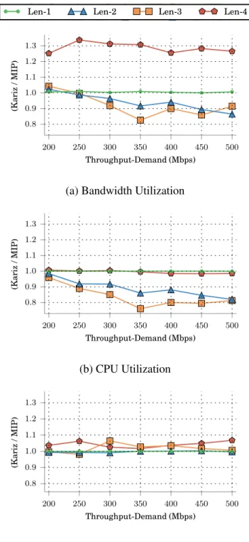
Figure2.7compares the resource utilization of Kariz with MIP’s. Bandwidth/CPU utilization for Kariz and MIP are the ratio of allocated bandwidth/CPU resources over aggregated band-width/CPU capacities in the network. For Middlebox resources, the reports are the average of per-middlebox throughput utilization.
The bandwidth utilization ratios as depicted in Figure2.7aare 100-101% for Len-1, 86-102% for Len-2, 83-104% for Len-3, and 125-134% for Len-4. Figure2.7a and Figure 2.6cshow that Kariz efficiently utilizes the bandwidth resources for Len-1, Len-2, and Len-3 for various throughput-demands. Regarding Len-4, Kariz’s efficiency in utilizing bandwidth resources decreases.
The CPU utilization ratios are in the range of 100-100% for Len-1, 82-98% for Len-2, 76-96% for Len-3, and 98-101% for Len-4, as observed in Figure2.7b. According to Figure 2.7band Figure2.6c, Kariz utilizes CPUs efficiently, close to MIP’s.
Finally, the instance utilization ratios vs. MIP are shown in Figure2.7c. The following ranges are reported: 100-100% for Len-1, 99-100% for Len-2, 98-106% for Len-3, and 102-107%. Kariz utilizes middlebox instances with an efficiency close to that of MIP for different lengths and throughput demands.
2.5.4
Operational Costs
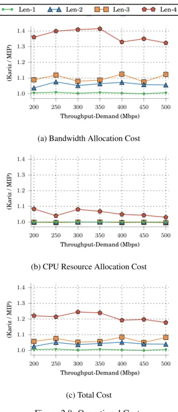
Figure2.8shows Kariz’s costs vs MIP’s. We collect Kariz’s and MIP’s average of per-chain costs. The reported values are the ratio of Kariz’s and MIP’s costs.
As shown in Figure 2.8a on average, Kariz allocates bandwidth resource vs. MIP in the range 100-101% for Len-1, 104-108% for Len-2, 108-113% for Len-3, and 132-141% for Len-4. Regarding CPU as presented in Figure 2.8b, on average, the same number of CPU cores is allocated for Len-1, Len-2, and Len-3. For Len-4, Kariz allocates 3-8% more CPU cores.
Finally, in respect to the total operational cost in Figure2.8c, the following cost ratios vs MIP are observed: 100-101% for Len-1, 103-105% for Len-2, 105-108% for Len-3, and 117-124% for Len-4. Kariz is more cautious to allocate CPUs than to allocate bandwidth showing that improvement rounds (see Section2.4.2) optimize the total cost by releasing CPUs while allocating more bandwidth. In summary, Kariz incurs a competitive per-chain cost that is less than 124% of MIP’s.
1.0
Len-1 Len-2 Len-3 Len-4
200 250 300 350 400 450 500 Throughput-Demand (Mbps) 0.8 0.9 1.0 1.1 1.2 1.3 (K ar iz /M IP )
(a) Bandwidth Utilization
200 250 300 350 400 450 500 Throughput-Demand (Mbps) 0.8 0.9 1.0 1.1 1.2 1.3 (K ar iz /M IP ) (b) CPU Utilization 200 250 300 350 400 450 500 Throughput-Demand (Mbps) 0.8 0.9 1.0 1.1 1.2 1.3 (K ar iz /M IP ) (c) VNF Utilization
1.0
Len-1 Len-2 Len-3 Len-4
200 250 300 350 400 450 500 Throughput-Demand (Mbps) 1.0 1.1 1.2 1.3 1.4 (K ar iz /M IP )
(a) Bandwidth Allocation Cost
200 250 300 350 400 450 500 Throughput-Demand (Mbps) 1.0 1.1 1.2 1.3 1.4 (K ar iz /M IP )
(b) CPU Resource Allocation Cost
200 250 300 350 400 450 500 Throughput-Demand (Mbps) 1.0 1.1 1.2 1.3 1.4 (K ar iz /M IP ) (c) Total Cost
2.6
Related Work
In this section, we discuss our work compare to the related work.
Selection: VNF-P [112] studies a hybrid deployment scenario using hardware-middleboxes and software middleboxes to provide a requested service. VNF-OP [11], [74], JoraNFV [168], and [104] model batch-deployments of multiple chains. [121] is a scheduling framework for deploying middlebox instances. These papers assume that instances of the same middlebox are identical. Slick [6] is a framework that allows users to write fine-grainedelementsto perform custom packet-processing. Predicting the performance of such arbitrary packet-processing element is not trivial. In contrast to these studies, we select appropriate middlebox instances from different typical offerings providing predictable performance.
Placement: Split/Merge [134] and OpenNF [58] redistribute packet-processing across a col-lection of instances. In contrast to DSFC, they do not focus on placement optimization models. Stratos [56] orchestrates instances on a remote cloud. It uses a rather simple technique that places instances of middleboxes in a chain as closely as possible to each other. JVP [93] considers the relation of bandwidth usage and host resource usage in the deployment of chains. However, JVP instantiates a single VM for each middlebox type. VNF-OP [11] and VNF-P [112] place all instances of a middlebox on a single machine. In contrast to these works, we place multiple instances of each middlebox distributedly. Luizelli et al. [103] only optimize the placement of mid-dleboxes and does not consider the routing. CoMb [142] is an architecture designed to consolidate the chain deployment. In contrast to DSFC, CoMb places all instances of middleboxes in a chain that deal with the same session at a fixed location. Such deployments consolidate middleboxes of a chain on the same server to multiplex substrate resources and reuse processing modules of a server across multiple middleboxes. However, these deployments limit chain performance to the resources of an individual server.
Routing: Unlike our work, [47,130,175] optimize only bandwidth usage. In processing a network flow, Slick [6] uses a single instance for each middlebox. On the contrary, DSFC routes traffic among multiple instances for each middlebox. Stratos [56] solves the routing separately after placing instances. LightChain [74] optimizes the number of switches between ingress and egress points of chains. The authors of [62] solve the joint placement and routing problem using a dynamic programming algorithm. E2 [121] instantiates instances in certain servers to optimize the inter-server communication. Although [11,62,112,121] coordinate the placement and routing,
they still treat the selection separately. We jointly optimize routing, placement, and selection that was not the focus of these studies.
Virtual network embedding: Our problem has similarities to virtual network embedding (VNE) problem that deals with mapping virtual nodes and links onto a substrate network [49,138]. However, our problem is fundamentally different; virtual links are part of the input to the VNE problem, while communication links between middlebox instances are unknown in our problem, and the solution must find these links.
2.7
Conclusion and Future Work
The limitations of current optimization models restrict a chain’s throughput to resources of a physical-machine and result in sub-optimal resource utilization and service performance. In this chapter, we presented distributed service function chaining (DSFC) to overcome these limitations. DSFC decouples a chain’s throughput from physical servers by placing instances of a middlebox in multiple servers. Furthermore, DSFC optimizes network utilization by coordinating the deployment operations.
We formulated DSFC using a mixed integer programming (MIP) model and proved its NP-Hardness for substrate networks with general graph topologies. An interesting future research direction is to analyze the complexity of our problem for specific datacenter topologies, such as fat-tree and VL2 [66].
For larger scales, we proposed and evaluated a heuristic called Kariz. The experimental results for various chain lengths and throughput demands demonstrate that Kariz achieves competitive cost and acceptance ratio compared to the MIP model. Kariz can be also adapted to deployreorder compatible chains[9], i.e., their middleboxes can be reordered without affecting the semantics of the chains. The number of valid chains generated using reordering are small because service function chains are short, commonly with less than six middleboxes [92], and many reorderings are invalid because they result in changing the chain semantics [9]. Thus, we can generate possible valid chains, compute their deployment costs using Kariz, and select a chain with the lowest cost.