Techniques for Efficient Regular Expression Matching Across Hardware Architectures
_______________________________________ A Thesis
presented to
the Faculty of the Graduate School at the University of Missouri-Columbia
_______________________________________________________ In Partial Fulfillment
of the Requirements for the Degree Master of Science
_____________________________________________________ by
XIANG WANG
Dr. Michela Becchi, Thesis Supervisor July 2014
The undersigned, appointed by the dean of the Graduate School, have examined the the-sis entitled
TECHNIQUES FOR EFFICIENT REGULAR EXPRESSION MATCHING ACROSS HARDWARE ARCHITECTURES
presented by Xiang Wang,
a candidate for the degree of master of science,
and hereby certify that, in their opinion, it is worthy of acceptance.
Professor Michela Becchi
Professor Harry Tyrer
ii
ACKNOWLEDGEMENTS
First and foremost, I would like to thank my research advisor Michela Becchi for her advising and teaching during my graduate study. Her enthusiasm and dedication inspired me to overcome difficulties and realize new ideas. I am extremely grateful for her instructions not only on academic research but also on normal life. I also learned how to share, respect and become a better person from her.
I have been so lucky to work with my friends in the NPS lab. In particular, I would like to thank all the lab members, including Kittisak, Daniel, Henry, Ruidong and etc, for the knowledge they shared and the happiness they provided.
I have been so fortunate to have summer intern at Micron Technology. It was great pleasure to work with knowledgeable people there. I am thankful for their help on both my work and life. I enjoyed this experience and benefited a lot from it.
I am thankful to my nice friends for bringing me the beautiful life here in Columbia during these years. Especially, I will always remember the everlasting friendship with Yuanhao, Lei, Yifan, Yi, Xiangjie, Sangdi, Haidong, Xiao, Xiuyi, Muhan and Luyao.
Finally, I am extremely grateful for having a nice family. With their encouragement and support, I became more confident and optimistic about my study and life. In particular, I have great parents who taught me with patience and help me to solve challenging problems.
Thank you!
Xiang University of Missouri-Columbia,
iii
TABLE OF CONTENTS
ACKNOWLEDGEMENTS ... ii
LIST OF FIGURES ...vi
LIST OF TABLES ... viii
ABSTRACT ...ix Chapter1 Introduction... 1 1.1 Contributions... 2 1.2 Organization ... 2 Chapter 2 Background ... 4 2.1 Regular Expressions... 4 2.2 Finite Automata ... 5
2.2.1 Introduction to NFA and DFA ... 6
2.3 Introduction to GPUs ... 7
2.3.1 General GPU Architecture ... 8
2.3.2 GPU Memory Hierarchy ... 9
2.3.3 Threads and blocks on GPUs ... 10
2.4 Introduction to Automata Processor ... 11
2.4.1 General Design... 11
2.4.2 Automata Processor Elements ... 13
iv
Chapter 3 Regular Expression Matching On GPU ... 16
3.1 Basic Implementation on GPU ... 16
3.2 Alphabet Reduction ... 17
3.3 Selection of GPU Memory for Alphabet Transition Table ... 18
3.4 Per-DFA vs. Shared Alphabet Translation Tables ... 20
3.5 Regular Expression Clustering Algorithm ... 20
3.5.1 Single Set Implementation ... 21
3.5.2 Double Set Implementation ... 23
3.6 Experimental Evaluation ... 25
3.6.1 Pattern-sets ... 25
3.6.2 Effect of GPU Memories ... 26
3.6.3 Multiple Tables vs. Single Table ... 28
3.6.4 Effect of Number of DFAs ... 30
3.6.5 Comparison of DFAs generation algorithms ... 31
Chapter 4 ANML Implementation ... 33
4.1 ANML Workbench ... 33
4.2 Data Structures for ANML Parser and Generator ... 35
4.3 ANML Parser ... 36
4.3.1 API functions of ANML parser ... 38
v
4.4.1 API functions of ANML generator ... 40
4.5 Optimization Techniques ... 41
Chapter 5 FPGA implementation... 44
5.1 General Design... 44
5.2 Design Optimizations... 47
5.3 Experimental Evaluation ... 49
5.3.1 Effect of Average Node Outdegree ... 50
5.3.2 Effect of Number of States ... 51
5.3.4 Real Regular Expression Pattern-set Evaluation ... 52
5.3.5 1D Cellular Automaton ... 54 5.3.6 2D Cellular Automaton ... 56 Chapter 6 Summary ... 60 6.1 Future Work ... 61 REFERENCES ... 63 VITA... 66
vi
LIST OF FIGURES
Figure Page
Fig. 2.1: (a) NFA and (b) DFA accepting regular expressions a+bc, bcd+ and cde. Accepting states are bold. States active after processing text aabc are colored gray. In the NFA, ∑ represents the whole alphabet. In the DFA, state 4 has an incoming transition on character b from all states except 1 (incoming
transitions to states 0, 1 and 8 can be read the same way). ... 6
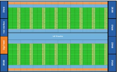
Fig. 2.2: Baseline architecture of Fermi GPU... 8
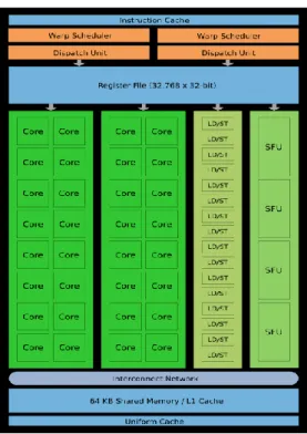
Fig. 2.3: Architecture of streaming multiprocessor on Fermi GPU ... 9
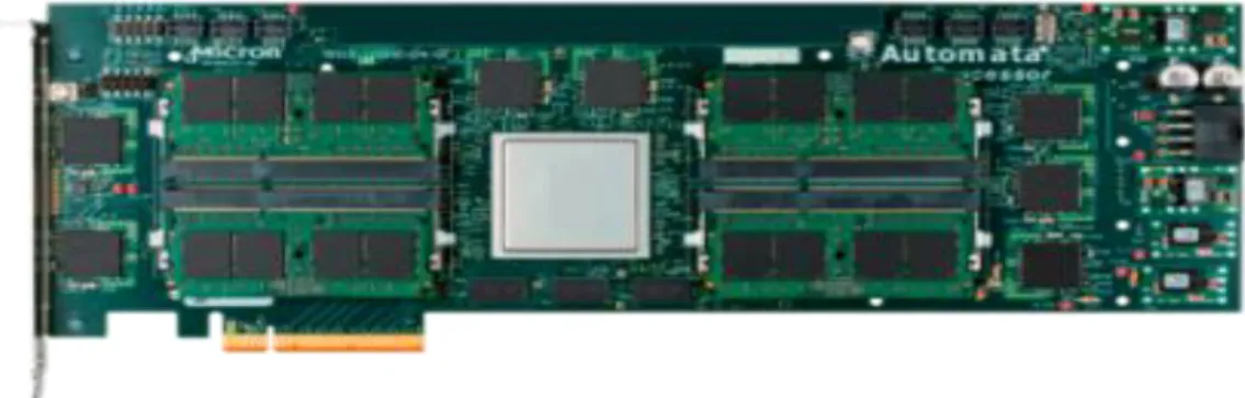
Fig. 2.4: Micron Technology’s Automata Processor. ... 11
Fig. 2.5: Use of start-of-data and all- input STEs to identify if matching starts at the beginning or anywhere in a given string respectively. ... 13
Fig. 2.6: (a) Structure of a logic cell and (b) LUT encoding scheme. ... 15
Fig. 2.7: Interconnections between CLBs. ... 15
Fig. 3.1: Flow charts of (a) single set implementation and (b) double set implementation. ... 23
Fig. 3.2: Comparison of number of DFAs generated by two algorithms. ... 32
Fig. 4.1: ANML workbench... 34
Fig. 4.2: Organization of data structures to represent Automata Networks... 35
Fig. 4.3: Structure of Element class. ... 36
Fig. 4.4: Structure of STE class. ... 36
Fig. 4.5: Structure of counter class. ... 36
Fig. 4.6: Structure of boolean class.. ... 36
Fig. 4.7: Transfer from XML file to Automata Network. ... 37
Fig. 4.8: API functions of ANML parser. ... 38
Fig. 4.9: ANML generator workflow. ... 39
vii
Fig. 4.11: Sample code to export Automata Networks to XML file... 41
Fig. 4.12: Effect of NFA reduction algorithm. Accepting states are colored grey. ... 42
Fig. 4.13: Implementation of alphabet reduction algorithm. Accepting states are colored grey. ... 43
Fig. 5.1: (a) Automata Network and (b) logic representation through one-hot encoding scheme. The INIT signal is asserted on the first character of a new input stream. The MATCH signal is asserted upon matching the pattern. ... 44
Fig. 5.2: General FPGA design. ... 46
Fig. 5.3: Verilog sample code to implement Automata Networks. ... 47
Fig. 5.4: Slice utilization of different average outdegrees per state. ... 50
Fig. 5.5: FPGA performance of different average outdegrees per state. ... 50
Fig. 5.6: Resource utilization of different number of states. ... 51
Fig. 5.7: FPGA performance of different number of states ... 52
Fig. 5.8: Slice utilization of spyware and backdoor. ... 53
Fig. 5.9: FPGA performance of spyware and backdoor. ... 54
Fig. 5.10: Design of 1DCA cell. ... 54
Fig. 5.11: 1DCA with 3 cells. ... 54
Fig. 5.12: Resource utilization of 1DCA. ... 55
Fig. 5.13: FPGA Performance of 1DCA. ... 56
Fig. 5.14: Design of 2DCA ... 57
Fig. 5.15: 3x3 2DCA. ... 57
Fig. 5.16: Resource utilization of 2DCA. ... 59
viii
LIST OF TABLES
Table Page
Table 2.1: Access latency of GPU memories. ... 10
Table 2.2: Resource availability in one chip on Automata Processor. ... 14
Table 3.1: Weight assigned to different character sets. ... 22
Table 3.2: Weight distribution of regular expressions in pattern-sets. ... 26
Table 3.3: Characteristics of DFAs. ... 27
Table 3.4: Throughput (in Mbps) obtained with multiple tables and different memory implementations... 28
Table 3.5: Throughput (in Mbps) obtained with single table and different memory implementations... 29
Table 3.6: Characteristics of DFAs generated by double sets implementation. ... 30
Table 3.7: Throughput (in Mbps) obtained from DFAs generated by double sets implementation. ... 31
Table 4.1: Counter Types. ... 40
Table 4.2: Mapping between boolean elements and type numbers. ... 40
Table 5.1: Rule 110 for 1D Cellular Automaton. ... 55
ix
TECHNIQUES FOR EFFICIENT REGULAR EXPRESSION
MATCHING
ACROSS HARDWARE ARCHITECTURES
Xiang Wang
Dr. Michela Becchi, Thesis Supervisor
ABSTRACT
Regular expression matching is a central task for many networking and bioinformatics applications. For example, network intrusion detection systems, which perform deep packet inspection to detect malicious network activities, often encode signatures of malicious traffic through regular expressions. Similarly, several bioinformatics applications perform regular expression matching to find common patterns, called motifs, across multiple gene or protein sequences. Hardware implementations of regular expression matching engines fall into two categories: memory-based and logic-based solutions. In both cases, the design aims to maximize the processing throughput and minimize the resources requirements, either in terms of memory or of logic cells.
Graphical Processing Units (GPUs) offer a highly parallel platform for memory-based implementations, while Field Programmable Gate Arrays (FPGAs) support reconfigurable, logic-based solutions. In addition, Micron Technology has recently announced its Automata Processor, a memory-based, reprogrammable hardware device. From an algorithmic standpoint, regular expression matching engines are based on finite automata, either in their non-deterministic or in their deterministic form (NFA and DFA, respectively). Micron’s Automata Processor is based on a proprietary Automata Network,
x
which extends classical NFA with counters and boolean elements.
In this work, we aim to implement highly parallel memory-based and logic-based regular expression matching solutions. Our contributions are summarized as follows. First, we implemented regular expression matching on GPU. In this process, we explored compression techniques and regular expression clustering algorithms to alleviate the memory pressure of DFA-based GPU implementations. Second, we developed a parser for Automata Networks defined through Micron’s Automata Network Markup Language (ANML), a XML-based high-level language designed to program the Automata Processor. Specifically, our ANML parser first maps the Automata Networks to an internal representation. We then apply NFA optimization techniques designed for other architectures to this internal representation. Finally, we implemented a tool to convert our internal representation to Verilog, thus allowing automatic deployment on FPGA. Our toolchain allows the user to apply existing optimization techniques to Micron’s Automata Processor and to directly compare this new platform with FPGA-based solutions.
1
Chapter1 Introduction
Pattern matching is at the center of many applications in a variety of domains. For example, deep packet inspection in network security and genome sequence search in the bioinformatics area highly rely on pattern matching. To detect malicious network activities and avoid network intrusion, most networking applications perform regular expression matching on packets. To discover specified gene sequences which may cause particular diseases, the searches of common gene sequences are conducted for different sequence samples.
Regular expression matching has been traditionally performed using finite automata, either in their deterministic or in their non-deterministic form (DFA and NFA, respectively). These data structures reduce the search process to a basic graph traversal guided by the symbols in the input stream. Both the NFA and DFA data structures can be deployed on different hardware platforms. Network processors, ASICs (Application-Specific Integrated Circuits) and FPGAs are widely used in network devices for packet inspection. Due to their massive computational power, GPGPUs (General Purpose GPUs) have proven to be a viable candidate for regular expression matching on large datasets. In addition, Micron Technology has recently announced their Automata Processor, a memory-based accelerator of NFA-wise computations.
In this thesis, we study the deployment of regular expression matching on three hardware platforms: GPUs, FPGAs and Micron’s Automata Processor. In particular, we consider the effective deployment of DFA-based search engines on GPU, and of NFA-based search engines on FPGA and on the Automata Processor.
2
1.1 Contributions
In this thesis, we discuss regular expression matching on different hardware platforms and propose algorithms to further optimize these implementations. Our main contributions can be summarized as follows.
First, we implement a compression algorithm for DFA to fit the limited GPU memory resources. We consider different implementation alternatives that are suited to the GPU architecture and its memory hierarchy. Furthermore, we propose two regular expression clustering algorithms that allow generating relative compact DFAs to fit the GPU memory even in the presence of complex pattern-sets.
Second, we develop a programming interface for Micron’s Automata Processor. Micron’s Automata Processor accelerates the traversal of so-called Automata Networks, which are extensions to NFA with counter and boolean element. Those Automata Networks can be represented through an XML-based language called ANML (Automata Network Markup Language). We develop an ANML generator and parser. The former allows deploying our optimized NFA onto the Automata Processor. The latter allows importing existing ANML specification into C++ data structures for optimizations (such as NFA reduction, alphabet reduction and so on).
Finally, we develop an automatic Verilog generator to transfer Automata Networks to Verilog files that target FPGA implementation.
1.2 Organization
3
background on finite automata and the hardware platforms we used in our research. In Chapter 3, we describe the design of our DFA-based search engine targeting GPU. We also propose a DFA compression algorithm and two regular expressions clustering algorithms. In Chapter 4, we present the implementation of our ANML parser and ANML generator as useful tools for both Micron’s Automata Processor and FPGA. In Chapter 5, we discuss the deployment of Automata Networks on FPGAs by developing a generator to convert NFA or Automata Networks to Verilog files. Finally, in Chapter 6, we summarize our main results and discuss several future research directions.
4
Chapter 2 Background
In this chapter, we provide background on regular expressions matching. In Section 2.1, we discuss regular expression. In Section 2.2, we provide an introduction to NFA and DFA. In the remaining sections, we provide background on the considered hardware platforms, namely GPU, FPGA and Micron’s Automata Processor.
2.1 Regular Expressions
A regular expression is a sequence of characters and special symbols that represent a set (possible infinite) of exact-match strings. The features found in regular expressions can be classified into different categories.
Exact-match patterns represent a simple string with fixed length. The Aho-Corasick DFA construction algorithm [1] can be used in the case of exact-match patterns.
Character sets accept a set of symbols and can be represented in two ways. First, it can be represented in the form [c1-c2c3], ci being any character of the alphabet. For
ex-ample, [a-cz] represents the combination of character ‘z’ and a character range that starts from ‘a’ and ends at ‘c’. The second way is by special symbols, such as space characters (\s), all digits (\d), all alphanumerical characters (\w), and their complements (\S, \D, \W). In addition, both single characters and character sets can be repeated, using expressions such as c+, c*, [c1c2]+ and [c1c2]*.
Wildcards are represented by a single dot symbol. The wildcard repetition called dot-star (.*) is commonly found in complex regular expressions derived from anti-viruses
5
and network intrusion detection systems and may cause DFA size explosion when large sets of regular expressions are combined.
Finally, counters allow bounded or infinite repetitions of particular characters or pat-terns. For instance, a{1,99} matches a sequence of characters ‘a’ ranging from 1 to 99 in length. As analyzed in [3], both counters and wildcards may lead to state blow-up when performing NFA to DFA transformation.
2.2 Finite Automata
Regular expression matching has traditionally been implemented by representing the pattern-set through finite automata (FA) [14], either in their deterministic or in their non-deterministic form (DFA and NFA, respectively). The matching operation is equivalent to a FA traversal guided by the content of the input stream. Worst-case guarantees can be met by bounding the amount of processing performed per character. Being the basic data structure in the regular expression matching engine, the finite automaton must be deployable on a reasonably provisioned hardware platform. As the size of pattern sets and the expressiveness of individual patterns increase, limiting the size of the automaton becomes challenging. The exploration space is characterized by a trade-off between the size of the automaton and the worst-case bound on the amount of per character processing.
NFAs and DFAs are at the two extremes in this exploration space. NFAs [14, 19] have a limited size but can require expensive per-character processing, whereas DFAs offer limited per-character processing (only one state transition is taken for each input character) at the cost of a possibly large automaton.
6
2.2.1 Introduction to NFA and DFA
In Figure 2.1, we show the NFA and DFA accepting three simple patterns (a+bc,
bcd+ and cde). In the two diagrams, states active after processing text aabc are colored gray. In the NFA, the number of states and transitions is limited by the number of sym-bols in the pattern-set. In the DFA, every state presents one transition for each character in the alphabet (Σ). Each DFA state corresponds to a set of NFA states that can be simul-taneously active [14]; therefore, the number of states in a DFA equivalent to an N-state NFA can potentially be 2N. In reality, previous work [3, 7, 17, 24] has shown that this so-called state explosion happens only in the presence of complex patterns (typically those containing bounded and unbounded repetitions of large character sets).
From an implementation perspective, existing regular expression matching engines can be classified as either memory-based [3-4, 7-8, 12, 15-17, 24, 33] or logic-based [6, 9, 23, 27]. For the former, the FA is stored in memory; for the latter, it is stored in com-binatorial and sequential logic. Memory-based implementations can be deployed on vari-ous platforms (GPUs, network processors, ASICs, FPGAs); logic-based implementations typically target FPGAs. In the latter case, updates in the pattern-set require the underlying platform to be reprogrammed. In a memory-based implementation, the design goals are to
Fig. 2.1: (a) NFA and (b) DFA accepting regular expressions a+bc, bcd+ and cde. Accepting states are bold. States active after processing text aabc are colored gray. In the NFA, ∑ rep-resents the whole alphabet. In the DFA, state 4 has an incoming transition on character b from all states except 1 (incoming transitions to states 0, 1 and 8 can be read the same way).
a 0 1 4 7 2 5 8 3 6 9 a b c b c d d c d e ∑ (a) c: from1,3,5-10 0 1 4 8 2 5 9 3 6 10 a b c b c d c d e 7 d e d d remaining transitions b: from2-10 a: from1-10 (b)
7
minimize the memory size needed to store the automaton and the memory bandwidth needed to operate it. Similarly, in a logic-based implementation, the design should aim at minimizing the logic utilization while allowing fast operation (that is, a high clock fre-quency). Typically memory-based implementations use a DFA representation, whereas logic-based implementations use an NFA design.
Existing proposals targeting DFA-based, memory-centric solutions have focused on two aspects: (i) designing compression mechanisms to minimize the DFA memory foot-print; and (ii) devising novel automata to be used as an alternative to DFAs in case of state explosion. Despite the complexity of their design, memory-centric solutions have three advantages (i) fast reconfigurability, (ii) low power consumption, and (iii) limited flow state; the latter leading to scalability in the number of flows. The one-hot encoding scheme [13] is at the center of all logic-based designs listed above. By encoding each FA state through a flip-flop, this scheme enables easy implementation of NFAs in logic, while limiting the processing time to one clock cycle per input character (both in the av-erage and in the worst case). Unfortunately, by distributing the state information across the FPGA, this solution does not allow easy and efficient context switching between packet flows. In other words, NFA-based, logic-centric solutions allow one to easily achieve peak worst-case performance on a single flow, at the expense of higher power consumption and of a lack of scalability in the number of concurrent flows.
2.3 Introduction to GPUs
GPUs were originally designed for graphic processing. Nowadays, these platforms are considered more general purpose, and regarded as efficient accelerators for a variety
8
of applications. Many scientific applications have been accelerated on NVIDIA GPUs, whose programmability has greatly improved since the advent of the CUDA programming model. We will give a brief introduction to NVIDIA Fermi GPUs [20] that we have used in this research.
2.3.1 General GPU Architecture
In general, GPUs are composed of a number of Streaming Multiprocessors (SMs). Figure 2.2 shows the baseline architecture of Fermi GPU, which consists of 16 SMs and has up to 6 GB of global memory. The host interface connects the GPU to the CPU via a PCI-Express.
In Figure 2.3, we can see the general architecture of a single SM. As can be seen, each SM consists of many simple, in-order cores (usually 32 or 48 for Fermi architecture). 32 threads are grouped into a warp and warps are scheduled on each SM through a warp scheduler. At the same time, a dispatch unit will dispatch different threads to different cores and functional units that will execute the threads’ computation. Threads are also grouped into thread-blocks. Multiple thread-blocks can be mapped to a single SM and multiple threads can be mapped to a single core.
9
2.3.2 GPU Memory Hierarchy
GPUs have a different memory hierarchy compared to CPU. GPU memories can be classified into 2 categories: on-chip and off-chip memories. First, as for on-chip memory, registers have low access latency and are shared by thread-blocks mapped to the same SM. Second, each SM has a configurable shared memory/L1 cache. Threads within the same block can share the data that reside in the on-chip shared memory on each SM. On the other hand, as a representation of off-chip memory, global memory is the most frequently used one with the largest size and is responsible for the direct communication with host through PCI-e. In addition, constant memory is a cached 64KB read-only memory that belongs to off-chip memory and is shared by all the thread blocks.
As shown in Table 2.1, different kinds of memories provide different access latencies. In general, the GPU memory organization consists of high latency global
10
memory, high latency local memory, low latency read-only constant memory, low-latency read-write shared memory. Therefore, shared memory and constant memory should be preferred when latency is a concern, while global memory needs to be used when memory size requirements become large. Therefore, the judicious use of the memory hierarchy and of the available memory bandwidth is essential to achieve good performance. Detailed considerations about the selection of GPU memories for our DFA-based search engine will be described in Section 3.3.
2.3.3 Threads and blocks on GPUs
Different from other parallel programming models, like POSIX threads [22] and OpenMP [21], CUDA [10] exposes to the programmer two degrees of parallelism: fine-grained parallelism within a thread-block and coarse-fine-grained parallelism across multiple thread-blocks. We can distribute work to a large number of threads by using unique iden-tifiers assigned to threads and blocks. Threads are grouped into warps (32 threads/warp), which operate in a SIMD (Single instruction, multiple data) manner. The configurations of threads and thread-blocks affect the overall performance. Too small configurations cause GPU resource underutilization, while too large configurations result in resource conflicts and in the serialization of parallel computations.
11
2.4 Introduction to Automata Processor
The Automata Processor (AP) [11], as shown in Figure 2.4, is an adoption of SDRAM technology designed to be used as a reconfigurable device for the direct implementation of non-deterministic finite automata (NFA) [11].
2.4.1 General Design
The Automata Processor comprises of an array of thousands of state transition elements (STEs) and a routing matrix. An STE is associated with each state in the mapped automata and stores one state bit that marks if the corresponding state is active or not. Each STE also contains a 256-bit symbol array (indexed by the current input) to process the input symbol. The output of symbol recognition and state bit determine the output of the STE. The output of each STE determines if another STE will become active or inactive after the current input symbol. The next state outputs from all the STEs are connected in parallel to a programmable routing fabric called the “routing matrix”. The routing fabric is comprised of an array of switching blocks that allows any STE to communicate with any other STE within a certain physical distance, allowing for a
12
maximum out-degree (fan out) of 16 from most states. Larger out-degrees are possible at the cost of reduced clock rate. Since one STE is associated with each state and is capable of activating another STE, each STE can conceptually be thought of as representing an edge, instead of a state, from the automaton description. The next state tables (and thus edge labels) are stored in the STEs, while the NFA topology is encoded into the configuration of the routing matrix. STEs can be individually marked as being an incoming edge into a start state or an outgoing edge into an accepting state, allowing for multiple start and accepting states. Also, start edges can be further classified as start-of-data or all-input-start, allowing for a simple representation of automata that match substrings.
In general, the Automata Processor consists of 6 ranks, each comprising 8 chips. Patterns can be loaded into the Automata Processor from an object file. Multiple input streams can be scanned in parallel. The Automata Processor thus is able to scan 8~48 flows in parallel and operate at the rate of 128MBps for each rank.
The Automata Processor implements Automata Networks, an extension to NFA, ei-ther from PCRE (Perl Compatible Regular Expressions) or from ANML (Automata Net-work Markup Language). PCRE file can be automatically compiled into a loadable object file by using a compiler provided by Micron Technology. At the same time, ANML, an XML-based language for programming Automata Networks, can be used to construct patterns in the form of XML files that can be further compiled into loadable objects.
13
2.4.2 Automata Processor Elements
The Automata Processor has 3 basic functional elements: STEs, counters and boole-an elements. Each STE represents the normal state in a classical NFA, while counters boole-and boolean elements are used along with STEs to increase the space efficiency of automata implementations and extend the computational capabilities beyond NFA.
A STE can be either configured as start-of-data or all-input to represent a start state as provided in Figure 2.5. In addition, a matching STE has an ‘R’ symbol in the lower right corner. Furthermore, a STE can also be defined as latched which means it will keep being active after once being activated. Finally, unlike classical NFA with labeled transi-tions, the matching symbols are integrated with the STE (that is, the accepted symbols are associated to the states rather than to the transitions).
Counters allowed some specified patterns to occur for a specified amount of times. Counters include two input ports: count and reset respectively. A target count and counter type should be configured for each counter in advance. In particular, there are three dif-ferent counter types that can be implemented, namely roll, pulse and latch counters. Like normal counters, the roll counter is reset each time the target value is reached and ready for the next activation. The latch counter persistently activates the elements connected to
Fig. 2.5: Use of start-of-data and all-input STEs to identify if matching starts at the beginning or anywhere in a given string respectively.
*
a b
14
it on the cycle on which the counter value reaches the target count. The counter value holds at the target and always activates the elements connected to it. The pulse counter activates the elements connected to it on the cycle on which the counter value reaches the target count and on subsequent cycles does not activate the connected elements. The counter value holds at the target but never activate the elements connected to it.
Boolean elements are particularly useful to achieve the functionality of boolean op-erators, like OR, AND, NOR, NAND, SoP (Sum of products) and PoS (Product of sums).
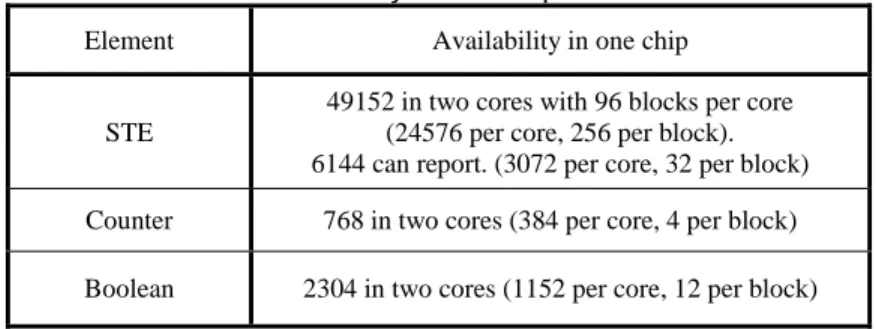
Table 2.2 shows the resource availability in one chip on the Automata Processor. Each chip consists of two cores and each core has 96 blocks. We have rich STE resource while have limited number of counters and boolean elements in each block. In general, the Automata Network is a powerful extension of classical NFA and therefore especially useful for implementing a variety of pattern matching applications.
2.5 Introduction to FPGAs
An FPGA [18] is a type of integrated circuit (IC) that can be configured to imple-ment a variety of functions in hardware. An FPGA consists of thousands of programma-ble logic cells shown in Figure 2.6(a). As we can see in this figure, each cell is composed of a look-up table (LUT), a flip-flop and a multiplexer.
Table 2.2: Resource availability in one chip on Automata Processor.
Element Availability in one chip
STE
49152 in two cores with 96 blocks per core (24576 per core, 256 per block). 6144 can report. (3072 per core, 32 per block) Counter 768 in two cores (384 per core, 4 per block) Boolean 2304 in two cores (1152 per core, 12 per block)
15
The LUT allows performing logic operations. It can be configured to encode simple logic functions like in Figure 2.6(b). It can also be used as distributed memory. Flip-flops are memory elements storing 1-bit of information. They can be configured to be triggered by a positive- or negative-edge clock. The multiplexer feeding the flip-flop could be config-ured to accept the output from the LUT or a separate input to the logic block.
In Xilinx FPGAs, a slice consists of multiple programmable logic cells and a con-figurable logic block (CLB) is made up of multiple slices. As shown in Figure 2.7, fast programmable interconnections also exist between different CLBs.
FPGAs can be programmed using a hardware description language (HDL), like Ver-ilog and VHDL. By making use of these languages, we can easily construct the logic functions that we need to implement. HDL specification can then be processed by synthe-sis, map, place and route. The outcome of this process is a bit file that can be loaded on the FPGA thus programming its hardware.
Fig. 2.7: Interconnections between CLBs.
Fig. 2.6: (a) Structure of a logic cell and (b) LUT encoding scheme.
16
Chapter 3 Regular Expression Matching On GPU
Since DFAs have the potential of state explosion for complex regular expressions, generating DFA representations without exceeding the GPU memory size becomes an important problem. We propose techniques to reduce the DFA size and optimize regular expression matching on GPU. This chapter is structured as follows.
In Section 3.1, we show the basic approach to implement regular expression matching on GPU. In Section 3.2, we discuss an optimization algorithm called alphabet reduction. We propose different approaches to implement alphabet reduction on GPU in Section 3.3 and 3.4. In Section 3.5, we describe two novel clustering algorithms for regular expressions. Our algorithms allow achieving smaller number of DFAs that fit GPU memory. Finally, in Section 3.6 we perform experiments on both real and synthetic pattern-sets using our DFA-based search engine.
3.1 Basic Implementation on GPU
Since GPUs are memory-based hardware platforms. In this case, DFA representation is preferred. DFAs need to be stored in GPU global memory. We take advantage of the uncompressed DFA-based solution from [34]. In general, different threads process different DFAs in the same thread-block. Different input streams are again mapped onto different thread-blocks. Because the ASCII table size is 256, we will store 256 transitions for each state in the memory layout. However, if the regular expression is complex and causes the DFA to have large number of states, the memory requirement may exceed the
17
GPU memory capacity. In this case, we can apply the alphabet reduction algorithm described in Section 3.2 to reduce the size of transition table and we can implement the clustering algorithms discussed in Section 3.5 to divide the regular expressions into partitions and generate smaller number DFAs that fit memory size.
3.2 Alphabet Reduction
The idea at the basis of alphabet reduction is the following: in a DFA recognizing regular expressions over an alphabet , each state has potentially || outgoing transitions, one for each symbol in . However, can be partitioned into classes of symbols C1,..,Ck
which are indistinguishable for the purposes of the DFA operation. Two symbols ci and cj
will fall into the same class if they are treated the same way in all DFA states. In other words, given the transition function (states, )states, (s,ci)= (s,cj) for each state s in
the DFA. Once the class translation C() {1..k} has been computed, the alphabet is reduced from cardinality || to k. k next state transitions will therefore suffice at each
procedure alphabet_reduction (DFA dfa=(n, δ(states, Σ)), modifies set class); (1) int alphabet_size = 0;
(2) for state s ∈states do
(3) for state t ∈ states do
(4) set char_covered[|Σ|] = false; (5) set class_covered[|Σ|] = false; (6) set remap[|Σ|] = 0;
(7) for (char c ∈Σ & δ(s,c)=t) do (8) char_covered[c] = true; (9) class_covered[class[c]]=true; (10) for (char c ∈Σ) do
(11) if (!char_covered [c] & class_covered[class[c]]) then
(12) if (remap[class[c]]==0) then remap[class[c]]= ++alphabet_size;
(13) class[c]=remap[class[c]]; end;
18
state. An additional alphabet translation table encoding the symbol-to-class mapping is required to allow the pattern matching operation. In practical scenarios (ASCII alphabet) this table will contain 256 entries, with a maximum width of 1 byte (for heavily compressed alphabets 5-6 bits per character may suffice). This indexing table can be efficiently cached or stored in on-chip memory. The algorithm of alphabet reduction is shown in the pseudo code above.
To compute the required alphabet translation tables, we use a parallel variant of the alphabet compression algorithm proposed in [4], which has O(n2) time complexity. Spe-cifically, we first construct a separate translation table for each state and then build a global alphabet translation table by progressively merging the state-specific tables from the first phase. On a 8-core processor, our implementation achieves a 4-5x speedup com-pared to the original single-threaded version [4].
Unfortunately, alphabet reduction becomes less effective as the size of the dataset (and of the corresponding DFA) increases. In fact, on large DFAs it is less likely for different symbols to cause transitions to the same target states. Therefore, in this study we combine alphabet compression with regular expression partitioning. In particular, we propose two new regular expression clustering methods in Section 3.5, and we compare them with the bisection-based scheme proposed in [5].
3.3 Selection of GPU Memory for Alphabet Transition Table
In our implementation, each alphabet translation table consists of 256 1-byte entries, thus requiring 256 B of memory. Below, we discuss advantages and disadvantages of storing the alphabet translation tables in different GPU memories.
19
• Given its large size (from 1 to about 12 GB depending on the GPU), global memory can easily accommodate a large number of alphabet translation tables. The main disadvantage of global memory is its high access latency.
• Shared memory offers low access latency at the cost of a limited capacity (from 16KB to 48KB per SM, depending on the configuration). The main limitation of shared memory is the following. Shared memory is SM-specific and has the scope of a single thread-block. If multiple thread-blocks with cumulative shared memory requirements exceeding the available capacity are mapped onto the same SM, their execution is serialized. Thus, storing a large number of alphabet translation tables in shared memory will limit the scalability in the number of packet flows. Specifically, given nAT alphabet translation tables, a shared-memory based implementation can scale up to 48KB/(256B×nAT) concurrent flows, and is more suited to pattern-sets that can be easily compiled into a small number of DFAs.
• Constant memory is read-only, has a 64KB size, is shared by all the thread-blocks, offers low access latency, and can be accessed in parallel to shared memory. If every thread in a half-warp requests data from the same address in constant memory, the GPU will generate only a single read request and subsequently broadcast the data to every thread. In addition, constant memory is cached, and therefore consecutive reads to the same address will not lead to any additional memory traffic. However, if the threads in a half-warp require different data, the corresponding 16 reads will be serialized. If multiple, per-DFA alphabet translation tables are used, this memory accesses serialization may impact the performance of our implementation, since different threads process different DFAs.
20
3.4 Per-DFA vs. Shared Alphabet Translation Tables
In general, alphabet translation tables can be either DFA-specific or shared across multiple DFAs. This design choice involves the following trade-off. Per-DFA alphabet translation tables typically result in smaller alphabets, thus reducing the amount of memory required to store the DFA state transition tables. However, as discussed above, multiple alphabet translation tables limit the flow scalability of shared-memory based implementations, and cause access serialization in constant-memory based implementations. On the other hand, sharing a single alphabet translation table across multiple DFAs generally leads to larger alphabets (it is more likely for a character to be treated differently in distinct DFAs), and thus to larger state transition tables (and memory requirements). As we will discuss in Section 3.6.3, we found the use of a single, shared alphabet translation table to be preferable.
3.5 Regular Expression Clustering Algorithm
In this section, we propose two regular expression clustering schemes aimed to mitigate the state explosion problem [3, 17, 33, 25]. Recall that, in our implementation (Section 3.1), each thread is responsible for the traversal of one DFA, and branch and memory divergence are the main obstacles to achieving high processing throughput. Therefore, when performing regular expression partitioning, it is important to alleviate this performance degradation by limiting the number of DFAs. At the same time, the size of each DFA must be kept small, so to limit the DFA memory requirements to the
21
available GPU capacity. Since we need GPU global memory to store packets, we allocate 80% of global memory to store DFAs.
In order to limit the number of DFAs encoding a particular pattern-set, we need to consider the complexity of each regular expression in that set. Combining many complex patterns in a single DFA can lead to state explosion and prohibitive memory requirements [3, 33]; on the other hand, equally distributing complex regular expressions into multiple DFAs allows limiting the size of each DFA. Smaller DFA have also the benefit of faster generation and compression (for example, alphabet compression has a time complexity which is quadratic in the number of DFA states). Below, we present two schemes to achieve this goal.
3.5.1 Single Set Implementation
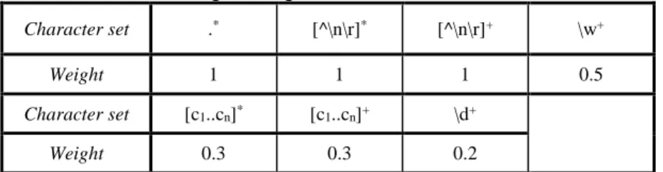
As explained in previous work [3, 33], state explosion is linked to the presence of particular sub-patterns in the regular expressions (typically repetitions of wildcards and large character sets). To drive our clustering scheme, we assign a weight to problematic sub-patterns that are frequently found in practical datasets. Specifically, the selected weights depend on the degree of state explosion that each sub-pattern may cause when combining multiple regular expressions into a single DFA. Table 3.1 shows the weights associated to various character set repetitions. Sub-patterns .*, [^\n\r]* and [^\n\r]+ are the most problematic, since they always lead to combinatorial state explosion when com-bining regular expressions; therefore, they are associated the maximum weight value. Other character set repetitions, such as \w+, \d+ and [c1..cn]+ (with n<20), may also
22
expressions in the same set. Since \w represents all alphanumerical characters, the weight
associated to \w+ is larger than that associated to \d+ (\d represents only digits) and
[c1..cn]+ (for small n).
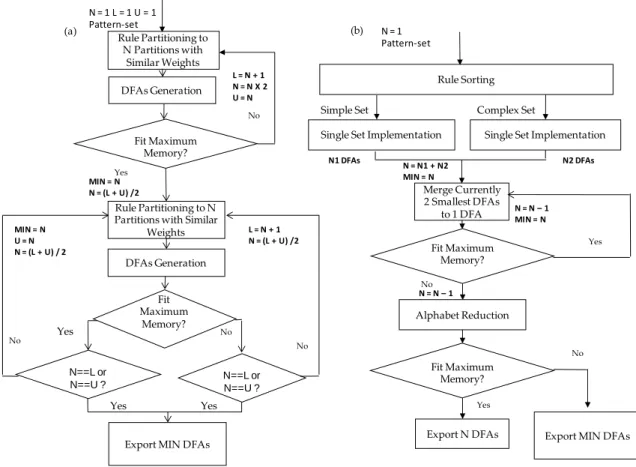
Figure 3.1(a) shows the flow diagram of the single set clustering algorithm. As we can see from it, after preprocessing the weights of each regular expression rule, we start from trying to generate a single DFA (N=1). We double the number N and distribute rules to get N rule partitions with even total weights until the total size of N DFAs fits the memory requirement (80% of global memory). At the same time, we update the lower bound L to be N+1 and upper bound U to be 2N each time we need to double the value of N. Then we continue to search for the minimum number of DFAs between the lower bound L and upper bound U. By using a method similar to binary search, each time we set N = (L+U)/2 and redefine the value of upper or lower bound. When we reach the edge condition (N==L or N==U), we will export the smallest number of DFAs that fit memory requirement. In this way, we can find the smallest number of DFAs which satis-fy the GPU memory requirement relatively fast.
Table 3.1: Weight assigned to different character sets.
Character set .* [^\n\r]* [^\n\r]+ \w+
Weight 1 1 1 0.5
Character set [c1..cn]* [c1..cn]+ \d+
23
3.5.2 Double Set Implementation
Single set implementation distributes rules with similar complexity evenly to DFAs in order to get as small number of DFAs as possible. We make the following observa-tions. First, since we want to get a small number of DFAs, we need to gather as many rules, both simple and complex ones, as possible. Second, a complex rule with weight larger than 3 will increase the DFA number of states and potentially causes large DFA. This conflict occurs when we want to gather as many simple rules as possible and at the same time combine them with complex rules. The more simple rules we gather, the larger the DFA size will become and also the larger DFA state replication we will get when
Fig. 3.1: Flow charts of (a) single set implementation and (b) double set implementation.
Yes
Rule Partitioning to N Partitions with
Similar Weights
Rule Partitioning to N Partitions with Similar
Weights
DFAs Generation
Export MIN DFAs Fit Maximum Memory? N==L or N==U ? Yes N = 1 L = 1 U = 1 Pattern-set No No N = 1 Pattern-set
Single Set Implementation Single Set Implementation Rule Sorting Merge Currently 2 Smallest DFAs to 1 DFA Fit Maximum Memory? Fit Maximum Memory? Alphabet Reduction
Export N DFAs Export MIN DFAs No
Yes
Yes No
Simple Set Complex Set
(a) (b) L = N + 1 N = N X 2 U = N DFAs Generation MIN = N N = (L + U) /2 Fit Maximum Memory? No Yes L = N + 1 N = (L + U) /2 MIN = N U = N N = (L + U) / 2 N = N – 1 MIN = N N = N1 + N2 MIN = N N1 DFAs N2 DFAs N = N – 1 N==L or N==U ? No Yes
24
combined with complex rules. In this case, large state replication will prevent us from getting relatively small number of DFAs that fit the memory requirement. Therefore, we need to divide relatively simple rules and complex rules into two sets to avoid rapid state increase. We allocate the memory size for each set according to the formulas below:
Memcomplex =Weightcomplex/(Weightcomplex+Weightsimple) *MemTotal Memsimple=Weightsimple/(Weightcomplex+Weightsimple) *MemTotal
Since we need GPU global memory to store packets, we define Memtotal as 80% the size
of global memory and use it to store DFAs generated from both simple set and complex
set. We then allocate the percentage of Memtotal to complex set according to the ratio of
its total weight (Weightcomplex) to the total weight of this pattern-set (Weight com-plex+Weightsimple). Similarly, we give the percentage of Memtotal to simple set according to
the ratio of its weight (Weightsimple) to the total weight of this pattern-set.
The details about double set implementation are shown in Figure 3.1(b). As we can see from it, we divide the rules into two sets named simple and complex by sorting all the rules. If there are rules with weight larger than the threshold we defined, they are classi-fied as complex rules. Otherwise, they belong to the simple set. We then implement the single set implementation discussed in Section 3.5.1 for both simple and complex sets separately to find the minimum number of DFAs. In addition, we define the maximum memory size as Memcomplex and Memsimple for complex set and simple set respectively in
the single set implementation. We then merge the smallest two DFAs to one among all the DFAs and update the smallest number (MIN) of DFAs until the total size of DFAs is larger than Memtotal. Finally, we perform alphabet reduction. If the total size is not larger
25
implementation. Otherwise, we export the smallest number (MIN) of DFAs that fit
Memtotal before the last merging. We add merge stage to our new algorithm because of the
potential to merge DFAs in these two sets. In this way, we can avoid the case that some DFAs in either set are very small which can be further combined to get smaller total number of DFAs.
3.6 Experimental Evaluation
In this section, we evaluate different alphabet reduction implementations for regular expression matching on GPUs. In addition, we compare the results of our DFA generation algorithms designed for regular expression matching on GPUs. Our experiments are conducted on an 8-core Intel Xeon E5620, running Centos 5.9. The system is equipped with an Nvidia GeForce GTX 480 GPU, comprising 15 32-core SMs. We used CUDA 5.5.
3.6.1 Pattern-sets
We use both real and synthetic pattern-sets in our experiments to evaluate the performances of our system. The real pattern-sets, consisting of backdoor and spyware rules are drawn from Snort NIDS [26]. These real pattern-sets have various symbol sets (.*, [^\n\r]* and counters) and up to 7 .* in the most complex patterns. The synthetic pattern-sets are generated by using the tool from [5] and tokens from the Snort rules. We used 4 synthetic pattern-sets called exact-match (E-M), dotstar0.05, dotstar0.1 and dotstar0.2. Exact-match only has exact match patterns, while dot-star pattern-sets contain
26
a varying fraction of unbounded repetition of wildcards (5%, 10% and %20 respectively). As for the number of rules, backdoor and spyware have 226 and 462 rules respectively. All synthetic pattern-sets consist of 1000 rules. In Table 3.2, we show the weight distributions of regular expressions in each of these pattern-sets.
All the packets used in our experiments are generated from the tool described in [5]. By giving 15 probabilistic seeds and 4 traversal probabilities called PM (35%, 55%, 75%
and 95%) which indicate the malicious level of the packets, we generate 15 1-MB trace files for each pattern-set. In addition, we conduct all our experiments by setting the packet size to 64KB.
3.6.2 Effect of GPU Memories
Our first goal is to compare the performances of the three GPU implementations of alphabet reduction described in Section 3.3 (namely implementations using global memory, shared memory and constant memory). Table 3.3 shows the basic characteristics of the DFAs generated for different pattern-sets in our experiments. Since the original alphabet size is 256, by comparing this value with the number of classes after alphabet reduction in column 4 of Table 3.3, we find that the memory size requirement can be saved up to 7.8 times for a single DFA. By comparing column 4 and column 5 in Table 3.3, we can see the merging of multiple alphabet transition tables would increase the
Table 3.2: Weight distribution of regular expressions in pattern-sets.
Dataset # Regular expressions <1 [1,2) [2,3) [3,4) [4,6) >=6 Spyware 462 83 337 12 20 2 8 Backdoor 226 147 63 9 5 2 0 Dotstar0.05 1000 953 44 3 0 0 0 Dotstar0.1 1000 911 78 11 0 0 0 Dotstar0.2 1000 825 151 23 1 0 0
27
overall alphabet size. Since characters that belong to the same class in one DFA may lead to different transitions in other DFAs, we need to do further classifications within a single class when merging multiple alphabet transition tables. In Table 3.4, we compare the per-formances of multiple-table implementation using different GPU memories. We perform our experiments using different number of 64KB packet flows per SM. The use of the optimal number of packet flows per SM (5 in this case) leads to up to 3X speedup over single packet flow per SM. We can first easily discover that the implementation on shared memory achieves the best performance across all the pattern-sets with different trace files because of its low memory access latency. The largest number of DFAs for a pattern-set (dotstar0.2) is 38 which require total 9.5KB to store all the tables per block. Therefore, the memory requirements to store alphabet transition tables don’t exceed the size of shared memory for all these pattern-sets and shared memory is the ideal location to store alphabet transition tables. Also, the performance by using global memory is be-tween shared memory and constant memory. The relatively high access penalty and low memory coalescing cause the performance of global memory to be not as good as those of shared memory. Finally, we notice the large performance gap between constant memory and the other two memories except for E-M pattern-set. The performance loss is
Table 3.3: Characteristics of DFAs.
Dataset # DFA # Total states
# Classes (before merging) # Classes (after merging) E-M 1 28744 88 88 Backdoor 13 960114 33 ~ 66 110 Spyware 32 95482 18 ~ 51 89 Dotstar.05 16 219330 43 ~ 87 90 Dotstar.1 32 157385 39 ~ 87 90 Dotstar.2 38 1194921 51 ~ 88 90
28
due to the serialization of the constant memory access. Since each thread in a block reads data from different tables (and different memory addresses), all the memory accesses in a half thread warp will be serialized. In the case of E-M, only one thread per block will be active and so constant memory accesses won’t be serialized.
3.6.3 Multiple Tables vs. Single Table
In Table 3.5 we show the results of performing regular expression matching on GPU using a single alphabet transition table. The following observations can be made. First, the implementation of single table on global memory has throughput improvement over the multiple alphabet transition tables one. Since a single alphabet transition table only occupies 256 bytes of memory (one byte for each character in ASCII table), the range of memory accessed for alphabet translation is limited to 256 bytes. Therefore, single table provides much larger potential of the GPU global memory coalescing which contributes
Table 3.4: Throughput (in Mbps) obtained with multiple tables and different memory imple-mentations.
Dataset PM = 0.35 PM = 0.55
Global Shared Constant Global Shared Constant
E-M 227.1 233.9 230.5 220.0 228.0 221.5 Backdoor 131.3 140.4 122.9 127.6 136.8 119.2 Spyware 111.9 122.6 87.9 112.5 121.9 91.7 Dotstar.05 144.6 162.6 132.1 145.0 162.2 139.5 Dotstar.1 111.0 122.4 86.8 111.9 122.6 95.2 Dotstar.2 53.1 59.2 25.0 12.8 13.2 10.6 Dataset PM = 0.75 PM = 0.95
Global Shared Constant Global Shared Constant
E-M 209.0 216.2 212.5 169.6 174.8 171.4 Backdoor 113.6 122.4 110.3 94.5 101.3 91.2 Spyware 111.4 120.5 89.5 96.6 101.8 77.3 Dotstar.05 108.1 116.3 105.9 113.6 119.4 111.0 Dotstar.1 111.6 119.8 90.0 91.8 96.2 76.6 Dotstar.2 53.0 58.8 26.8 12.7 13.2 10.6
29
to performance gain. Higher cache hit rate achieved by single table also has positive ef-fect on the results. Second, we can see the performance improvements by using shared memory. Because the GPU kernel needs to copy table information from global memory to shared memory at the beginning for each packet, better performances can be explained by fewer write operations on shared memory during each iteration. Third, the constant memory implementation benefits largely from single table and its performances are quite close to those of the shared memory implementation. In our single table implementation, the threads in a half warp are much more likely to access the same constant memory ad-dress. So there will be much less memory access serialization and the broadcast mecha-nism can further save certain amount of memory traffic. However, the weakness of single table is obvious compared to multiple-table implementation. We can see from Table 3.3 that merging alphabet transition tables will always create a single table with larger num-ber of character classes, thus requiring more global memory to store DFA state transition table.
Table 3.5: Throughput (in Mbps) obtained with single table and different memory implementation.
Dataset PM = 0.35 PM = 0.55
Global Shared Constant Global Shared Constant
E-M 230.5 237.4 235.6 223.9 230.5 228.0 Backdoor 147.3 150.1 153.1 142.0 145.0 146.0 Spyware 133.3 141.4 141.4 133.3 141.1 140.4 Dotstar.05 174.3 179.2 178.7 171.4 177.7 176.7 Dotstar.1 133.6 141.4 141.4 136.8 140.4 141.1 Dotstar.2 65.1 71.0 70.9 13.4 13.8 13.8 Dataset PM = 0.75 PM = 0.95
Global Shared Constant Global Shared Constant
E-M 215.5 216.9 219.2 174.8 173.8 175.7 Backdoor 126.1 128.7 131.1 98.9 103.8 103.5 Spyware 133.9 140.7 140.7 111.6 115.0 115.4 Dotstar.05 120.5 124.1 124.1 125.6 127.6 128.1 Dotstar.1 134.1 140.1 138.6 104.2 109.2 108.3 Dotstar.2 64.8 71.9 72.1 13.4 13.8 13.8
30
3.6.4 Effect of Number of DFAs
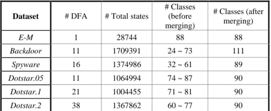
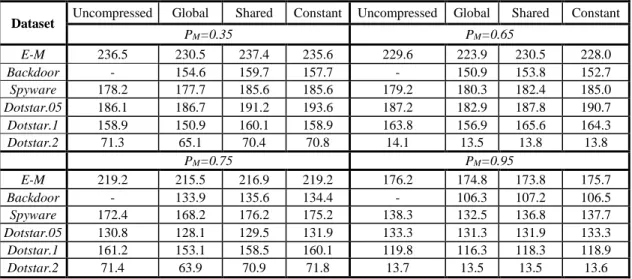
In this section, we analyze how the number of DFAs affects the overall performance. In Table 3.6, we can see the DFAs generated by our double set implementation. Table 3.7 shows the corresponding performance results and compares them with the original uncompressed version. Similar to the results in Table 3.5, shared memory and constant memory achieve competitive performances while the global memory-based implementation is not as good as the other two. We can also notice that in some cases, the implementation with alphabet reduction leads to higher throughput than the uncompressed one. This is because the smaller DFA state transition table can lead to more regular memory access patterns and therefore higher cache hit rate. By comparing Table 3.5 and Table 3.7, we can see that fewer DFAs result in better performances for the same pattern-set. As mentioned before, the number of threads per block to conduct pattern matching is reduced with smaller number of DFAs. In the GPU kernel function, each thread needs to check whether an accepting state is reached, which potentially leads to branch divergence. Also, each thread performs an atomic operation to record the match information further impacts the matching speed. Therefore, larger number of threads causes poorer performance. In general, from the experiments, we can conclude that the best performances are achieved when minimum number of DFAs that fit the available
Table 3.6: Characteristics of DFAs generated by double set implementation
Dataset # DFA # Total states
# Classes (before merging) # Classes (after merging) E-M 1 28744 88 88 Backdoor 11 1709391 24 ~ 73 111 Spyware 16 1374986 32 ~ 61 89 Dotstar.05 11 1064994 74 ~ 87 90 Dotstar.1 21 1004455 71 ~ 81 90 Dotstar.2 38 1367862 60 ~ 77 90
31
memory capacity is used. Another aspect to point out is that the total size of the DFAs generated for backdoor pattern-set before alphabet reduction is about 1.67GB, which is larger than our GPU global memory size. Therefore, the uncompressed approach is unable to process this pattern-set. Alphabet reduction can make this possible by reducing the size by nearly half.
3.6.5 Comparison of DFAs generation algorithms
In this section, we compare different DFAs generation algorithms discussed in Section 3.5. In Figure 3.2, we can see that the results of single set implementation are not as good as the others when dealing with complex pattern-sets like spyware. In spyware pattern-set, about 6.5% of the rules have weight larger than 3 and combining them with large amount of simple rules can cause large DFA state replication. Therefore, the number of DFAs generated for spyware using single-set implementation is relatively large. The number of DFAs generated using the single set implementation for backdoor
Table 3.7: Throughput (in Mbps) obtained from DFAs generated by double sets implementa-tion.
Dataset Uncompressed Global Shared Constant Uncompressed Global Shared Constant
PM=0.35 PM=0.65 E-M 236.5 230.5 237.4 235.6 229.6 223.9 230.5 228.0 Backdoor - 154.6 159.7 157.7 - 150.9 153.8 152.7 Spyware 178.2 177.7 185.6 185.6 179.2 180.3 182.4 185.0 Dotstar.05 186.1 186.7 191.2 193.6 187.2 182.9 187.8 190.7 Dotstar.1 158.9 150.9 160.1 158.9 163.8 156.9 165.6 164.3 Dotstar.2 71.3 65.1 70.4 70.8 14.1 13.5 13.8 13.8 PM=0.75 PM=0.95 E-M 219.2 215.5 216.9 219.2 176.2 174.8 173.8 175.7 Backdoor - 133.9 135.6 134.4 - 106.3 107.2 106.5 Spyware 172.4 168.2 176.2 175.2 138.3 132.5 136.8 137.7 Dotstar.05 130.8 128.1 129.5 131.9 133.3 131.3 131.9 133.3 Dotstar.1 161.2 153.1 158.5 160.1 119.8 116.3 118.3 118.9 Dotstar.2 71.4 63.9 70.9 71.8 13.7 13.5 13.5 13.6
32
and dotstar0.2 pattern-sets are also affected by the combination of complex regular expressions and large amount of simple regular expressions. By comparing these two algorithms, we can conclude that the double set algorithm is general enough to deal with both simple and complex pattern-sets. On the other hand, we need to identify the threshold to be used to divide simple and complex sets. According to the weight distributions of regular expressions in different pattern-sets shown in Table 3.2, we conduct experiments to see how the performances are affected by the weight threshold that distinguishes simple regular expression from complex one. As can be seen in Table 3.2, if we define the threshold to be 2, the percentage of complex regular expressions is not larger than 9% for all the pattern-sets. By separating the small amount of complex regular expressions from large number of simple regular expressions, we can avoid too many state replications. When the threshold becomes larger, more complex regular expressions are combined with simple regular expressions. Therefore, the number of DFAs generated tends to be larger.
Fig. 3.2: Comparison of number of DFAs generated by two algorithms.
0 5 10 15 20 25 30 35 40 45
E-M Backdoor Spyware Dotstar0.05 Dotstar0.1 Dotstar0.2
N u m b e r o f D F A s
33
Chapter 4 ANML Implementation
One of the central tasks in our research is related to pattern matching on Micron’s Automata Processor. Recall that this platform can be programmed by using ANML, an XML-based language to construct Automata Networks. Micron Technology also developed a graphic tool called ANML workbench to construct Automata Networks and export Automata Networks to XML files. We give an introduction to ANML workbench in Section 4.1. We develop tools to parse XML files and construct Automata Networks by using our C++ data structures. We show these data structures in Section 4.2. We created an ANML parser that allows transforming Automata Networks represented by these data structures for further optimizations (such as NFA reduction and alphabet reduction). We describe ANML parser in Section 4.3. In Section 4.4, we discuss a programming interface called ANML generator to generate Automata Networks using our data structures. Finally, in Section 4.5, we discuss optimization techniques for Automata Networks.
4.1 ANML Workbench
As shown in Figure 4.1, ANML workbench is the graphic tool to construct Automata Networks. We can use the available elements including STEs, counters and boolean elements in the upper right window on ANML workbench. We can also configure the properties for these elements, such as start properties of STEs, symbol sets of STEs, target count of counters and counter types of counters, in the lower right
34
window. We can add transitions between elements by drawing lines connecting them. Furthermore, we can encapsulate a particular pattern in a block called Macro object and then replicate Macro objects to represent the patterns that appear frequently in our designs. Therefore, the Macro object increases the reusability of patterns on ANML workbench and makes our design more convenient. The block in the middle right window is a Macro object that stores the pattern shown in the left window. To check the correctness of our designs, ANML workbench provides a simulator to simulate the matching process for the user provided input stream. In addition, we can use ANML workbench to export our designs to XML files in the format shown in the left of Figure 4.7.
35
4.2 Data Structures for ANML Parser and Generator
We use ANML parser to parser the XML files generated by ANML workbench and represent corresponding Automata Networks using our C++ data structures. On the other hand, we use ANML generator as the programming interface to construct Automata Networks. Therefore, both ANML parser and generator rely on the data structures we used to represent Automata Networks. In Figure 4.2, we show the general organization of our data structures. We create a base class Element to achieve the features shared by all the three elements. We then use 3 child classes inheriting from Element to represent STEs, counters, and boolean elements.
Figure 4.3 shows the base structure of Element class. The general design of Element class has the variable type to indicate which type this element belongs to. It also stores transition information between different elements and has the variable report to indicate if it is an accepting element. The ANFA class in Figure 4.4 has variables that are unique to STEs. In particular, ANML parser stores symbol information associate to STEs in the variable symbols. The start variable shows whether the STE is an all-input, start-of-data or normal state. If the STE keeps being active after once being activated, the latch variable is set to be true. In Figure 4.5, the counter class stores the information about target count in the variable count. We use the variable at_target to determine the type of counter (roll, pulse and latch). Similar to counter class, we use boolType to store the type
Fig. 4.2: Organization of data structures to represent Automata Networks.
STE Counter
Element