Filipe Marques Ferreira
HIGH CAPACITY OPTICAL TRANSMISSION SYSTEMS
BASED ON MODE DIVISION MULTIPLEXING
Tese de Doutoramento em Engenharia Electrotécnica e de Computadores, ramo de especialização em Telecomunicações, orientada pelo Senhor Professor Doutor Henrique José Almeida da Silva e coorientada pelo Senhor Doutor Daniel Diogo Ferrão da Trindade Fonseca, e apresentada ao Departamento de Engenharia Electrotécnica e de Computadores da Faculdade de Ciências e Tecnologia da Universidade de Coimbra.
Faculty of Sciences and Technology
Department of Electrical and Computer Engineering
High Capacity Optical Transmission
Systems Based on Mode Division
Multiplexing
Supervisor:
Professor Doctor Henrique Jos´
e Almeida da Silva
Co-Supervisor:
Doctor Daniel Diogo Ferr˜
ao da Trindade Fonseca
Thesis submitted in accordance with the requirements of the University of Coimbra for the degree of Doctor of Philosophy in Electrical and Computer Engineering
Filipe Marques Ferreira
This work was supported by Funda¸c˜ao para a Ciˆencia e a Tecnologia and Coriant Portugal Unipessoal Lda under Grant Agreement Number SFRH/BDE/51094/2010, and by European Communities 7th Framework Programme under Grant Agreement Number FP7-258033 (MODE-GAP).
Agradecimentos
Acknowledgments
Os presentes agradecimentos s˜ao endere¸cados a todas as pessoas que contribu´ıram com o seu apoio e colabora¸c˜ao para a elabora¸c˜ao do trabalho descrito neste documento. Agrade¸co ao meu orientador, Professor Doutor Henrique Silva por me introduzido no mundo das comunica¸c˜oes por fibra ´optica, pelo constante apoio, est´ımulo e disponi-bilidade, bem como pela cuidada supervis˜ao cient´ıfica do meu trabalho. Ao Professor Doutor Paulo Monteiro por me ter dado a inestim´avel oportunidade de fazer o meu doutoramento num ambiente estimulante na Coriant Portugal. Ao Doutor Daniel Fon-seca pela orienta¸c˜ao, apoio incans´avel e meticulosa aten¸c˜ao aos detalhes. Ao Doutor Sander Jansen pela sua orienta¸c˜ao no in´ıcio do meu doutoramento.
The following acknowledgments are addressed to all the people that have con-tributed with their support and collaboration for the success of this work. Firstly, I would like to express my sincere gratitude to my supervisor, Professor Doctor Hen-rique Silva for introducing me to the world of optical fiber communications, by the continued support, encouragement and availability, as well as by the careful scientific review of my work. I would like to thank Professor Doctor Paulo Monteiro for giving me the invaluable opportunity to do my Ph.D in a stimulating environment at Coriant Portugal. I wish also to thank Doctor Daniel Fonseca for his supervision, tireless sup-port, availability and painstaking scientific review of my work. In addition, I would like to thank Doctor Sander Jansen for his guidance in the beginning of my Ph.D.
No ˆambito do projecto ModeGap, agrade¸co `a Adriana Lobato, Beril Inan, Dirk van der Borne, Maxim Kuschnerov e Marc Bohn pelo empenho nas nossas discuss˜oes e resultados cient´ıficos, que resultaram num produtivo trabalho conjunto.
As a part of the ModeGap project, I would like to acknowledge Adriana Lobato, Beril Inan, Dirk van der Borne, Maxim Kuschnerov and Marc Bohn for their commit-ment in our scientific discussions and outcomes, resulting in a productive teamwork.
como me ajudaram a integrar em Lisboa e na Coriant. Ao Rui Morais, Jo˜ao Ferreira, Miguel Drummond e Jos´e Gir˜ao pelas vibrantes tert´ulias `a volta da mesa de almo¸co. Por todos os momentos bem passados agrade¸co ao Nelson Costa, Ant´onio Eira, Nataˇsa Pavlovi´c, Rui Meleiro, Fernando Jesus, Lara Pellegrino e Pedro In´acio. Em especial quero agradecer ao Paulo Almeida e ao Filipe Bugalho pela amizade que constru´ımos primeiro em Coimbra.
Finalmente, o agradecimento mais importante, aos meus pais, a quem devo tudo o que sou hoje. Os meus pais foram incans´aveis na forma como procuraram colocar-me sempre no colocar-melhor caminho e proporcionar-colocar-me as colocar-melhores condi¸c˜oes. `A minha irm˜a que tem estado sempre por perto.
Por fim, um agradecimento muito especial `a Vˆania Almeida pelo carinho, pela paciˆencia, pela compreens˜ao, e por todos os momentos bons que trouxeram felicidade a este caminho.
Abstract
The present work reports the investigation on high capacity optical transmission sys-tems based on mode division multiplexing (MDM) over few-mode fibers (FMFs). MDM over FMFs is as an attractive solution to overcome the impending capacity crunch of conventional single-mode fiber (SMF) systems, with potential cost, space, and energy savings. An N-fold capacity increase is obtained using a FMF with N
independent modes, since each mode can support the same amount of information of a SMF. However, there are some impairments arising from the multimode nature of FMFs, which have to be addressed in order to reach their full capacity: differen-tial mode delay (DMD), linear mode crosstalk (XT), mode-dependent loss (MDL), and inter-modal nonlinearities. Furthermore, a basic MDM-FMF system is composed by: mode multiplexers (MMUXs) and demultiplexers (MDMUXs), multimode ampli-fiers (MMAs), and multiple-input-multiple-output (MIMO) digital signal processing (DSP). The MMAs are a key component for economic and energy efficient MDM-FMF systems. In order to reduce cost and energy consumption in comparison to N paral-lel single-mode amplifiers, the MDM channels have to share the pumps power. One of the main difficulties experienced in the design of MMAs is the achievement of low mode dependent gain (MDG). The MMUXs/MDMUXs are responsible for an approx-imately unitary mapping from the input signals to the FMF modes and vice-versa, such that the transmission impairments can be reverted through MIMO-DSP.
In this thesis, the main impairments of MDM-FMF systems identified above are modeled, allowing to develop several techniques to reduce their impact. A nonlinear semi-analytical model (NSAM) for transmission over FMFs is developed. The design requirements of mode selective phase masks for MMUXs/MDMUXs are investigated regarding the mask resolution, mask phase noise and mask alignments. The design of FMFs with up to 12 non-degenerate linearly polarized (LP) modes, suitable for long-haul transmission, is addressed. Moreover, three methods to extend the transmission reach of MDM-FMFs, by limiting the accumulation of DMD and MDL/MDG along
possible techniques to reduce the corresponding induced penalty.
Keywords: mode division multiplexing, few-mode fibers, differential mode delay, linear mode crosstalk, mode dependent losses, inter-modal nonlinear effects.
Resumo
O presente trabalho relata a investiga¸c˜ao de sistemas de transmiss˜ao de alta ca-pacidade com multiplexa¸c˜ao por divis˜ao modal (MDM) em fibras com poucos mo-dos (FMFs). MDM em FMFs ´e uma solu¸c˜ao atractiva para ultrapassar a iminente exaust˜ao das fibras monomodais (SMFs) convencionais com uma poupan¸ca poten-cial no custo, espa¸co e consumo energ´etico. Um aumento da capacidade de N vezes pode ser obtido utilizando uma FMF comN modos independentes, uma vez que cada modo tem uma capacidade igual `a de uma SMF. Contudo, a natureza multimodal das FMFs introduz limita¸c˜oes ausentes nas SMFs: atraso modal diferencial (DMD), diafonia modal linear (XT), atenua¸c˜ao dependente do modo (MDL), e efeitos n˜ ao-lineares intermodais. Estas limita¸c˜oes tˆem que ser abordadas para cumprir todo o potencial das FMFs. Para al´em disso, um sistema MDM-FMF b´asico ´e composto por: multiplexadores modais (MMUXs) e demultiplexadores modais (MDMUXs), amplificadores multimodais (MMAs), e processamento digital de sinal (DSP) para sistemas de m´ultiplas entradas e m´ultiplas sa´ıdas (MIMO). Os MMAs s˜ao um com-ponente chave no projecto de sistemas MDM-FMF economicamente competitivos e energeticamente eficientes. A potˆencia das bombas tem que ser partilhada entre os canais MDM para atingir uma poupan¸ca no custo e consumo energ´etico. Uma das maiores dificuldades no projecto de MMAs ´e a obten¸c˜ao de um ganho dependente do modo (MDG) reduzido. Os MMUXs/MDMUXs s˜ao respons´aveis por um mapea-mento aproximadamente unit´ario entre os sinais de entrada e os modos guiados pelas FMF e vice-versa, para que seja poss´ıvel reverter os efeitos de transmiss˜ao utilizando DSP-MIMO.
Nesta tese, as principais limita¸c˜oes dos sistemas MDM-FMF acima identificadas s˜ao modeladas de forma a permitir o desenvolvimento de v´arias t´ecnicas para reduzir o seu impacto. Um modelo n˜ao-linear semi-anal´ıtico para a transmiss˜ao em FMFs ´e desenvolvido. O projecto de m´ascaras de fase para MMUXs/MDMUXs ´e realizado, especificando os requisitos na resolu¸c˜ao, ru´ıdo de fase e alinhamento. O projecto
m´etodos para a extens˜ao do alcance de transmiss˜ao de sistemas MDM-FMF atrav´es da redu¸c˜ao da DMD e MDL/MDG acumuladas. Finalmente, um estudo alargado dos efeitos n˜ao-lineares intermodais ´e apresentado, identificando os efeitos dominantes bem como potenciais t´ecnicas para a redu¸c˜ao da penalidade induzida pelos mesmos.
Palavras-chave: multiplexa¸c˜ao por divis˜ao modal, fibras com poucos modos, atraso modal diferencial, diafonia modal linear, atenua¸c˜ao dependente do modo, efeitos n˜ ao-lineares intermodais.
Contents
Agradecimentos . . . ix
Abstract . . . xiii
Resumo . . . xvii
Contents . . . xxii
List of Abbreviations . . . xxvi
List of Symbols . . . xxxii
List of Tables . . . xxxiii
List of Figures . . . xxxvii
1 Introduction 1 1.1 Motivation and Scope of the Thesis . . . 1
1.1.1 Few-Mode Fibers . . . 4
1.1.2 Mode-Division Multiplexing . . . 5
1.2 Objectives and Organization of the Thesis . . . 7
1.3 Main Contributions . . . 9 References . . . 10 2 Modern MDM-FMF Systems 15 2.1 Introduction . . . 15 2.2 Few-Mode Fibers . . . 16 2.2.1 Fiber Modes . . . 16 2.2.2 FMFs Impairments . . . 20 2.2.3 Modern FMFs . . . 27 2.3 Mode-Division Multiplexing . . . 30
2.3.1 Mode Multiplexers and Demultiplexers . . . 30
2.3.2 Multimode Amplifiers . . . 32 xix
2.3.3 MIMO DSP . . . 35 2.3.4 Progress in Systems Demonstrations . . . 37 2.4 Conclusions . . . 39 References . . . 39
3 Models for MDM-FMF Systems 47
3.1 Introduction . . . 47 3.2 Few-Mode Fibers Model . . . 48 3.2.1 FMF Linear Crosstalk . . . 48 3.2.2 FMF Nonlinear Propagation . . . 57 3.3 MMUX/MDMUX Model . . . 61 3.3.1 Phase Masks . . . 61 3.4 General Transmission Simulation Setup . . . 66 3.4.1 TMF Transmission Simulation . . . 67 3.5 Conclusions . . . 70 References . . . 70
4 Design of Few-Mode Fibers 73
4.1 Introduction . . . 73 4.2 Design of 2M-FMFs With Arbitrary DMD . . . 74 4.2.1 Fiber Profile Description, Analysis and Optimization . . . 74 4.2.2 Results and Discussion . . . 79 4.3 Design of xM-FMFs with Low DMD . . . 83 4.3.1 Fiber Profile Description and Analysis . . . 83 4.3.2 Optimization Function and Algorithms . . . 85 4.3.3 Optimization Results . . . 89 4.3.4 Manufacturing Margins . . . 94 4.4 Conclusions . . . 96 References . . . 97 5 Linear Transmission Impairments in FMFs 101 5.1 Introduction . . . 101 5.2 Reach Improvement using Fiber Splices . . . 102 5.2.1 Concept Discussion and Simulation Setup . . . 102
CONTENTS xxi 5.2.2 Simulation Results . . . 107 5.3 Alternative Reach Improvement Methods . . . 110 5.3.1 High Distributed Linear XT . . . 110 5.3.2 Maximum-Likelihood Detection . . . 111 5.4 Conclusions . . . 113 References . . . 114 6 Nonlinear Transmission Impairments in FMFs 116 6.1 Introduction . . . 116 6.2 MM-MW-CNLSE Derivation . . . 118 6.2.1 XPM and IM-XPM Analytical Solution . . . 123 6.2.2 FWM and IM-FWM Analytical Solution . . . 124 6.3 MM-MW-CNLSE Validation . . . 125 6.3.1 IM-XPM . . . 126 6.3.2 IM-FWM . . . 128 6.4 MDM-WDM-FMF Transmission . . . 130 6.4.1 XPM/IM-XPM . . . 131 6.4.2 FWM/IM-FWM . . . 133 6.4.3 MM-MW-CNLSE Validation for MDM-WDM Signals . . . 137 6.5 Conclusions . . . 138 References . . . 139
7 Conclusion and Future Work 142
7.1 Conclusions . . . 142 7.2 Future Work . . . 145 Appendix A Semi-Analytical Solutions for Three Modes 146 Appendix B Optimization of ILD-FMFs and DC-FMFs 151 B.1 Introduction . . . 151 B.2 Fiber Profile Description and Optimization . . . 152 B.3 Optimization Results . . . 154 B.3.1 ILD-FMFs . . . 154 B.3.2 DC-FMFs . . . 156
B.4 Conclusions . . . 158 References . . . 158 Appendix C Optimum xM-FMFs Characteristics 160
List of Abbreviations
BER bit-error rate.
CIR channel impulse response. CMA constant modulus algorithm. CMT coupled mode theory.
CNLSE coupled nonlinear Schr¨ondinger equations. CP cyclic prefix.
CW continuous-wave. DC DMD compensated. DC-FMF DMD compensated FMF. DCF dispersion-compensating fiber. DCI depressed-cladding index. DMD differential mode delay. DSP digital signal processing.
DWDM dense wavelength-division multiplexing. dXT distributed XT.
EDF erbium-doped fiber.
EDFA erbium-dopped fiber amplifier. ER extinction ratio.
FDE frequency-domain equalization. FEC forward-error correction.
FIR finite impulse response. FMF few-mode fiber.
FWM four-wave mixing.
GCCT graded-core and a cladding trench. GI graded-index.
GSS golden section search.
HCF hollow-core fiber. IL insertion loss.
ILD inherently low DMD. ILD-FMF inherently low DMD FMF. IM intensity modulation.
IM-DD intensity modulation with direct detection. IM-FWM inter-modal four-wave mixing.
IM-NL inter-modal nonlinear.
IM-XPM inter-modal cross-phase modulation.
ITU-T International Telecommunication Union-Telecommunication Standardization Sector. LCoS liquid crystal on silicon.
LED light emitting diode. LHS left-hand side. LP linearly polarized.
LPFG long period fiber grating. MBL macro-bend losses.
MC-MMF multicore-multimode fiber. MCF multi-core fiber.
MDD maximum DMD deviation. MDG mode dependent gain. MDL mode-dependent loss. MDM mode-division multiplexing. MDMUX mode demultiplexer.
MER mode extinction ratio.
MIMO multiple-input-multiple-output. ML maximum-likelihood.
MM-CNLSE multimode coupled nonlinear Schr¨odinger equations.
MM-EDFA multimode erbium-doped fiber amplifier. MM-MW-CNLSE multimode multi-wavelength coupled
nonlin-ear Schr¨odinger equations.
MM-RFA multimode Raman fiber amplifier. MMA multimode amplifier.
MMF multimode fiber.
MMSE minimum mean square error. MMUX mode multiplexer.
List of Abbreviations xxv MSI multiple-step index.
MTD maximum tolerable deviation. MW multi-wavelength.
NLSE nonlinear Schr¨odinger equation. NRZ non-return-to-zero.
NSAM nonlinear semi-analytical model. OF objective function.
OFDM orthogonal frequency division multiplexing. OOK on-off keying.
OSNR optical signal-to-noise ratio. PDM polarization-division multiplexing. PM phase mask.
PMD polarization-mode dispersion. PMF polarization maintaining fiber. QPSK quaternary phase-shift keying. RHS right-hand side.
RK45 Runge-Kutta 4th-5th order.
ROSNR required optical signal-to-noise ratio. RX receiver. SA semi-analytical. SDM spatial-division multiplexing. SE spectral efficiency. SI step-index. SM single-mode. SMF single-mode fiber. SMT single-mode transmission. SPM self-phase modulation. SSFM split-step Fourier method. SSMF standard single-mode fiber. sXT splice XT.
TDE time-domain equalization. TMF two-mode fiber.
TS training symbol. TX transmitter.
WDM wavelength-division multiplexing.
xM x non-degenerate LP modes. XPM cross-phase modulation. XT crosstalk.
List of Symbols
(ρd, φd) random position of the fiber core axis in
cylin-drical coordinates.
(ρ, φ) radial distance ρ and azimuth φ in a cylindri-cal coordinate system.
(x,y) abscissa and ordinate coordinates in Cartesian coordinate system.
α fiber core exponential decay factor.
αui attenuation of the polarizationi of mode u. βl,u lth order angular frequency derivative ofβu(ω)
atω =ω0.
βl,ui lthorder angular frequency derivative ofβui(ω)
atω =ω0.
βl,uvi lthorder angular frequency derivative ofβui(ω)
atω =ωv.
βu(ω) propagation constant of mode uat ω.
βui(ω) propagation constant of the polarization i of
mode u atω.
χ(3)xxxx third-order silica susceptibility.
δi1,i Kronecker delta, δi1,i = 1 for i1 = i and 0
otherwise.
δx random displacement of the abscissa coordi-nate.
δy random displacement of the ordinate coordi-nate.
∆n(ρ) relative refractive index difference profile. ∆nco relative refractive index difference profile at
ρ= 0.
∆ntr relative refractive index difference profile at
the trench of a GCCT profile.
∆βu1i1,u2i2,u3i3,ui phase mismatch between wavesu1i1,u2i2,u3i3
and ui, at ω =ω0.
∆βu1,u phase mismatch between modes u1 and u at ω=ω0.
∆ε(x, y) waveguide imperfection.
∆ni relative refractive index of stepiof a MSI
pro-file.
ε0 permittivity of free space. εp(x, y) ideal profile permittivity.
γu1u2u3u nonlinear coefficient between modes u1,u2,u3
and u.
k0 propagation constant in free space. λ wave wavelength.
µ0 permeability of free space. ω angular frequency.
ωz spatial frequency.
ψ DMD target for fiber profile optimization.
ψi groups the independent inter-modal
polariza-tion combinapolariza-tions.
ρd,max maximum random radial displacement of the
fiber core axis.
σuxF W M1u 2 variance of the symbol ”1” considering only the MM-MW-CNLSE xF W M terms for modes u1 and u.
σxXP M u1u
2
variance of the symbol ”1” considering only the MM-MW-CNLSE xXP M terms for modes u1 and u.
ξi groups the independent intra-modal
polariza-tion combinapolariza-tions.
aDM D average DMD of a DC-FMF segment.
Aef fu1u2u3u inter-modal effective area of mode combina-tion (u1, u2, u3, u).
Au(z, t) slowly varying field envelope of mode u. Aui(z, t) slowly varying field envelope of polarization i
mode u. ˜
Au(z, ω) time Fourier transform of Au(z, t).
˜
Aui(z, ω) time Fourier transform of Aui(z, t). AN U Mu mode u numerical amplitude solution.
ASA
u mode u semi-analytical amplitude solution. c0 light velocity in free space.
CT X-u coupling coefficient between the filtered SMF
LP01 mode incident on the FMF surface and
List of Symbols xxix
Cu,u1 linear XT coupling coefficient between mode u and modeu1.
CF W M nonlinear contribution due to FWM in the
MM-MW-CNLSE equation.
CIM-F W M nonlinear contribution due to IM-FWM in the
MM-MW-CNLSE.
CIM-XP M nonlinear contribution due to IM-XPM in the
MM-MW-CNLSE.
CIM-N L inter-modal nonlinear contribution in the
MM-CNLSE equation.
CIN T RA-N L intra-modal nonlinear contribution in the
MM-CNLSE equation.
CSP M nonlinear contribution due to SPM in the
MM-MW-CNLSE equation.
CXP M nonlinear contribution due to XPM in the
MM-MW-CNLSE equation.
du1v1,uv walkoff parameter between the (u1v1) pump
channel and the (uv) probe channel.
DM D differential mode delay parameter.
DM DLPµν DMD of the LP
µν mode measured relatively
to the LP01.
DM Du1,u DMD between two modesu1 and uatω =ω0,
whereu is the reference mode.
DM Du1vi1,uvi DMD between the polarization i1 of mode u1
and the polarization i of mode u at ω = ωv,
taking uvi as reference.
D chromatic dispersion parameter.
Du chromatic dispersion parameter of mode u at ω=ω0.
Duv chromatic dispersion parameter of mode u at ω=ωv.
Duvi chromatic dispersion parameter of the
polar-izationi mode u at ω=ωv.
e
E(r, ω) total electric field in the spectral domain. E(r, t) total electric field in the time domain.
Ei bi polarization component ofE(r, t).
FP M-SM F
LP01 phase mask design: LP01 field distribution
after transmission through the phase mask (PM).
FSM F
LP01 phase mask design: LP01 field distribution at
SMF front end.
Fu(x, y) electrical field distribution of mode u. FF M F
u phase mask design: phase of the electric field
distribution of the target FMF mode u.
Hu1 magnetic field distribution of mode u1.
HuxXP M1v1,u0(ω) linear transfer function of thexXP M induced intensity modulation in the (u, v = 0) probe channel associated with the (u1, v1) pump
channel.
bi unit linear polarization vector. j imaginary unit.
L fiber length.
lDM D DMD parameter of a ILD-FMF.
Ln length of the negative DMD FMF in a
DC-FMF segment.
Lp length of the positive DMD FMF in a
DC-FMF segment.
Ls fiber segment length.
maxDM D maximum DMD among the guided modes and over the defined wavelength range (maxDM D).
M BL macro-bend losses parameter.
M DD maximum DMD deviation relatively to the targeted DMD over the C-band.
M PxF W M
ba maximum input power per channel for a
Q-factor of 7 considering only the MM-MW-CNLSE xF W M terms for modes b and a.
M PxXP M
ba maximum input power per channel for a
Q-factor of 7 considering only the MM-MW-CNLSE xXP M terms for modes b and a.
M SEu mean squared error between the
semi-analytical results and the numerical results calculated for mode u.
List of Symbols xxxi
M T D maximum tolerable deviation of the fabricated fiber parameters for DM D≤12 ps/km.
n2 Kerr coefficient.
n(ρ) refractive index profile.
Nst number of steps of a MSI profile. ncl refractive index of the cladding. nco refractive index of the core axis.
nDM D DMD parameter the negative DMD FMF in a DC-FMF segment.
nu effective index of modeu.
nu
g effective group index of mode u.
Nu normalization factor for the field distribution
of mode u.
OF objective function for fiber profile optimiza-tion.
pDM D DMD parameter the positive DMD FMF in a DC-FMF segment.
e
PNL(r, ω) time Fourier transform of the nonlinear
polar-ization PNL(r, t).
PNL(r, t) nonlinear polarization due to the third-order
nonlinear silica susceptibility.
PN Li bi polarization component of PNL(r, t).
P SDpump(ω) power spectral density of an intensity
modu-lated pump.
Pu optical power of mode u atω =ω0.
Puv optical power of the channel at ω = ωv in
mode u.
PuvxF W M1,u1v2,u1v3,u0 power of the xF W M product generated at (u, v = 0) considering three CW signals in (uv1, u1v2, u1v3).
Q Q-factor.
QxF W M
u1u Q-factor of a channel in (u, v = 0) considering
three CW signals in (uv1, u1v2, u1v3). QxXP M
u1u Q-factor of a probe channel in (u, v = 0)
r position vector in Cartesian coordinates (x, y, z).
Rc fiber curvature radius.
S chromatic dispersion slope parameter.
Su chromatic dispersion slope parameter of mode u at ω=ω0.
Suv chromatic dispersion slope parameter of mode u at ω=ωv.
Suvi chromatic dispersion slope parameter of the
polarization i mode uat ω=ωv. sXT splice XT.
t time unit.
V normalized frequency.
vg,u group velocity of mode u. w1 fiber core radius.
w2 radial distance between the end of the core
and the beginning of the trench in a GCCT profile.
w3 trench width in a GCCT profile. wst step width of a MSI profile.
xF W M equal to FWM for u1 = u or equal to
IM-FWM for u1 6=u.
xXP M equal to XPM foru1 =uor equal to IM-XPM
for u1 6=u.
xM x non-degenerate LP modes.
XTu1,u XT from mode u to modeu1.
XTT X-u phase mask design: linear XT generated at the
transmitter during the conversion of the SMF LP01 into the FMF mode u.
z height coordinate in Cartesian coordinate sys-tem or distance of propagation.
zn discrete points considered in a specific fiber
List of Tables
2.1 LPlm fiber modes. . . 19
2.2 Summary of progress in FMFs design. . . 29 2.3 Summary of progress in MDM-FMF systems demonstrations. . . 38 3.1 Propagation constants differences at 1550 nm. . . 54 3.2 Fiber properties at 1550 nm. . . 68 4.1 Optimized fiber characteristics and parameters. . . 80 4.2 Maximum tolerable deviation of the optimum parameters [%]. . . 82 4.3 Optimized fiber parameters and characteristics for the optimum GCCT
profile with ∆nco= 1·10−3 and = 1. . . 91
4.4 Characteristics for the optimum MSI profiles. . . 92 6.1 Characteristics of the GI-FMF [10] and [11] at λ0 = 1545 nm. . . 126
6.2 Sets of wavelengths considered in [11]. . . 128 C.1 Characteristics for the Optimum GCCT Profile and Optimum MSI
profile. . . 161
1.1 Optical fibers capacity known physical dimensions. Multimode and multi-core fibers support multiple spatial modes. . . 3 1.2 Cross-section of a: (a) SMF, (b) 3C-MCF, (c) 7C-MCF, (d) 19C-MCF,
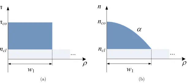
(e) FMF, (f) MMF, (g) MC-FMF and (h) HCF. . . 4 2.1 Simple refractive index profiles: (a) step-index (SI) and (b)
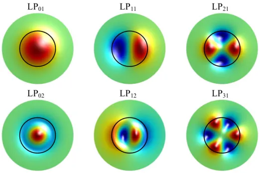
graded-index (GI). . . 16 2.2 Few modes field distribution. Black circle: core-cladding boundary. . . 18 2.3 bu as a function ofV for a few propagation modes in a parabolic index
fiber. . . 20 2.4 DM Du1,u as a function of V for a parabolic-index fiber, with u = LP01. 22
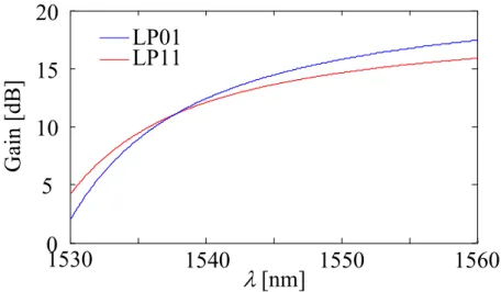
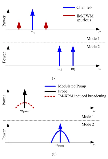
2.5 Example of deformations in: (a) fiber core-cladding boundary and (b) splices. . . 23 2.6 Idealized sketch of the mode gain of a 2M-MMA as a function of λ. . . 25 2.7 Schematic representation of the: (a) spurious signals generated by
inter-modal four-wave mixing (IM-FWM) and (b) spectral broadening in-duced by inter-modal cross-phase modulation (IM-XPM). . . 26 2.8 Basic system concept for a long-haul MDM system. . . 30 2.9 Main MMUX/MDMUX types: (a) PMs [8], (b) spot coupler [46] and
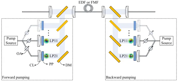
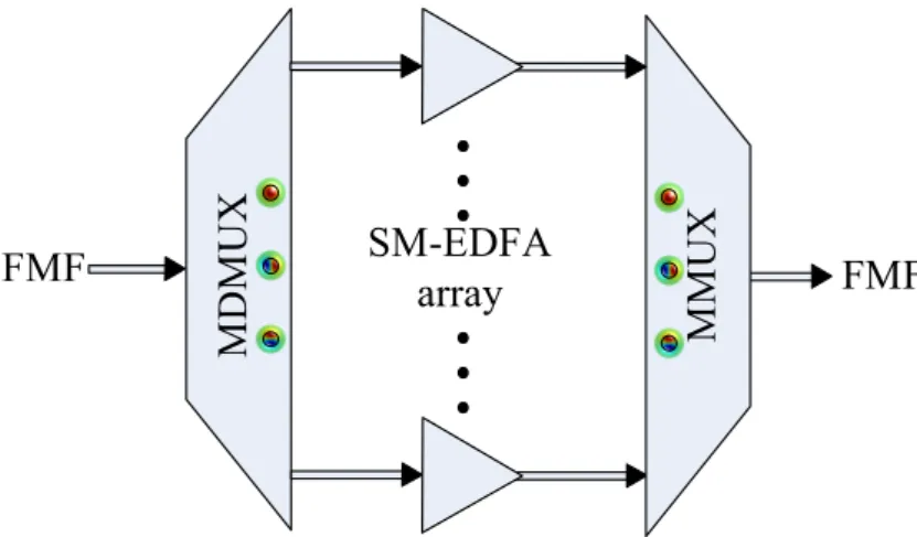
(c) photonic lantern [9]. . . 32 2.10 General MMA setup. Abbreviations: optical attenuator (OA), phase
plate (PP), collimator lens (CL) and dichroic mirror (DM). . . 33 2.11 MMA composed by M parallel SM-EDFAs. . . 34 2.12 DSP blocks in a digital coherent receiver. . . 35 3.1 Sketch of a fiber with distorted core-cladding boundary. . . 49 3.2 Plots the mode powers |A1|2 and |A2|2 as functions of the interaction
distance z, for (a) ∆β = 0 and for (b) ∆β = 4|κ|, withκ =π/2. . . 50 xxxiv
LIST OF FIGURES xxxv 3.3 (a) Normalized power in each of polarization modes as a function of
the fiber length. (b)XT as a function of the fiber length. . . 51 3.4 Cu,u1 (z-axis, orthogonal to the page) as a function of the fiber
dis-placement vector (xy-plane, page plane). . . 54 3.5 Normalized mode power as a function of the fiber length, for: (a)
A(0) =p1/6·[1 1 1 1 1 1], and (b) A(0) =p1/21·[1 2 3 4 5 6]. . . . 55 3.6 M SEu along the azimuthal coordinate as a function of ρd. . . 56
3.7 Sketch of the mode selective launching setup in the transmitter side. . . 62 3.8 ROSNR for a BER of 10−3 as a function of the XT introduced by the
hybrid coupler of a coherent receiver. . . 64 3.9 (a)XTT X-LP11a as a function of the PM pixel resolution. (b)XTT X-LP11a
as a function of the pixel grid offset. . . 65 3.10 XTT X-LP11a and CT X-LP11a as a function of the: (a) standard deviation
and (b) PM misalignment, for N = 256. . . 65 3.11 Long-haul MDM-WDM-FMF system setup. . . 66 3.12 log10(BER) for SMT over the TMF and over the SMF as a function of
the mode launch power, after 6000 km . . . 69 3.13 log10(BER) for MDM transmission over the TMF as a function of the
mode launch power, after 300 km. . . 69 4.1 GCCT profile. . . 75 4.2 ng of the LP01 and of the LP11 as a function of λ: (a) varying α; (b)
varying ∆ntr. Inset (a) and (b): Normalized amplitude of the field for
the LP01and LP11modes as a function ofρ/w1, consideringλ= 1550 nm. 77
4.3 Contour map of OF [ps/km] as a function of w2 and w3, for ψ = 0
ps/km. ”+” marks theOF minimum, which is 0.004 ps/km. . . 79 4.4 Optimumα and M DDas a function of ψ. . . 81 4.5 MSI profile with constantwst. . . 84
4.6 DMD [ps/km] as a function ofλ, for different ∆nco values. . . 85
4.7 (a) Contour map of maxDM D [ps/km] as a function α and ∆ntr. (b)
min
α (maxDM D) as a function of ∆ntr. . . 88
4.8 (a)maxDM D[ps/km] optimum values as a function of ∆nco for
differ-ent numbers of modes. (b)Rc [mm] as a function of ∆nco for different
numbers of modes. . . 90 4.9 Optimum MSI profile with 64 steps and optimum GCCT profile
con-sidering ∆nco= 1·10−3 as a function ofρ/w1, for: (a) 4M, (b) 6M, (c)
4.10 GCCT profile parameters MTD: (a)α, (b) ∆nco, (c) ∆ntr and (d) (w1, w2, w3). . . 95
4.11 MSI profile parameters MTD: (a)∆ni and (b) wst. . . 96
5.1 sXT, αS, and MDL as a function of the core displacement. . . 103
5.2 Span configuration: (a) ILD-FMF link and (b) DC-FMF link. . . 105 5.3 (a) CIR length as a function of fiber length, for m = 4 without splice
MDL. Normalized CIR for L= 80 km (b) and 1200 km (c). . . 106
5.4 ROSNR and available OSNR for the ILD-FMF link as a function of total length. . . 108 5.5 Distance reach for the ILD-FMF link as a function of (sXT,αS). . . . 108
5.6 Distance reach for the DC-FMF link as a function of (sXT, αS). . . 110
5.7 ROSNR penalty for different Goffset with: (a) low and (b) high dXT as
a function of the transmission distance. . . 111 5.8 Average and +/ standard deviation (vertical lines) of the ROSNR
penalty at a BER of 10−3, ML detection, ZF, and MMSE equaliza-tion, low and high dXT and Goffset of (a) 0.5 dB, (b) 1 dB, and (c) 2 dB
per span. . . 112 6.1 Contour map of SBF-RM SE [·10−2] as a function of DM Du10,u0 and
DM Du30,u20. Inset: Overlap of the experimental and simulation SB for
the optimum DMD values. . . 127 6.2 P Rmax as a function of DM Du10,u0 for wavelength set: (a) A, (b) B,
(c) C. . . 129 6.3 M PxXP M
ba as a function of DM Du10,u0, for each pair of modes (b, a):
(a) a=u2 and (b)a=u. . . 132
6.4 M PxF W M
ba as a function of DM Du10,u0, for each pair of modes (b, a):
(a) a=u2 and (b)a=u. . . 135
6.5 M PbaxF W M considering all IM-FWM terms falling into u as a function of DM Du10,u0, for flat DMD and non-flat DMD. . . 137
6.6 Q2 as a function of the power per carrier. . . 138
B.1 OFILD calculation example. . . 154
B.2 DM and DV as a function of β, for: (a) 4M and (b) 6M. DM DLPµν
as a function of λfor the optimum parameters with β = 0, for: (c) 4M and (d) 6M. . . 155
LIST OF FIGURES xxxvii B.3 (a) OFDC as a function of φ obtained using P1 and P2, for 4M and
6M. rDM D as a function of λ obtained using: (b) P1 for 4M, (c) P1 for 6M, (d) P2 for 4M and (e) P2 for 6M. (f) CIR length as a function of the total length for the optimum ILD-FMFs in section B.3.1. . . 157
Chapter 1
Introduction
1.1
Motivation and Scope of the Thesis
Fiber optic communication systems are today present in all telecommunication net-works: access, metropolitan area, regional, long-haul, ultra long-haul and submarine. The success of optical networks is truly spectacular, remembering that in the mid-1970s almost all communication systems relied on the transmission of information over electrical cables or unguided propagation of electromagnetic radiation. The suc-cess of optical networks has its roots in one critical invention: low-loss silica based optical fibers, namely single-mode fibers (SMFs). Modern SMFs present a loss of 0.17-0.35 dB/km over∼40 THz centered at∼200 THz, such as the so-called low water peak fibers like AllWaveTM and SMF-28eTM. The broad low-loss frequency band of SMFs allows transmitting large quantities of information over long distances. Other telecom-munications systems present frequency bands several orders of magnitude shorter: a few hundreds of MHz in satellite telecommunications, a few tens of MHz in digital subscriber lines, and a few tens of MHz in wireless systems.
The optical networks capacity has increased more than 10000 times since the sec-ond generation of commercial systems deployed in the 1980s with bit rates of∼1 Gb/s. In the mid-1990s, the introduction of wavelength-division multiplexing (WDM) and large bandwidth erbium-dopped fiber amplifiers (EDFAs) allowed an extremely rapid growth of the available capacity. At that time, the capacity growth was firstly achieved by increasing the number of channels and then increasing the bit rate per channel. Bit rates for WDM systems started at 2.5 Gb/s in the 1990s, increased to 10 Gb/s in 1996, and to 40 Gb/s in 2003. Up to 2003, almost all the optical transmission systems were using the intensity modulation with direct detection (IM-DD) scheme, by
ing the binary digits with different power levels. However, later on, the development of 40 Gb/s IM-DD systems has shown that the next capacity increase could not be attained by further increasing the bit rate per channel, since signal bandwidth could no longer be accommodated in a 50 GHz channel spacing grid (the most common grid spacing). Consequently, further capacity increase was obtained by increasing spectral efficiency (SE), using two properties of optical waves unexplored until then: phase and polarization. Today high-capacity systems use quadrature phase-shift keying (QPSK) modulation and polarization-division multiplexing (PDM). QPSK modulation consists on the encoding of two bits per time slot on four possible phase values, and PDM consists in sending simultaneously two independent signals (QPSK modulated, for example) into two orthogonal polarizations. However, modulation formats enhancing the spectral efficiency get increasingly susceptible to signal distortions induced by nonlinear effects on the optical fiber [1].
One main limitation of silica based fibers is its inherent nonlinearity, known as the Kerr effect [2]. The Kerr effect is responsible for introducing nonlinear signal distortion that increases with signal power, being the distortion increase faster than signal power increase. Consequently, there is a maximum quantity of information that can be transmitted over the low-loss frequency band in optical fibers. The capacity limit can be calculated using the Shannon-Hartley theorem modified to include fiber nonlinearities [1, 3]. The nonlinear capacity limit in SMFs depends on their physical properties, namely: attenuation, chromatic dispersion and nonlinear coefficients [3]. The nonlinear capacity limit for a 500 km long standard single-mode fiber (SSMF) is between 70 Tb/s and 175 Tb/s, using only the C-band and using the C+L band, respectively [1]. The ever growing demand for higher data rate will eventually drive the systems to approach the SSMFs nonlinear capacity limit.
The current annual growth rates of internet traffic and capacity of commercial optical fiber systems are approximately 50 % and 20 %, respectively [3]. Furthermore, the capacity of under development systems is a factor of 2 below the SSMFs nonlin-ear capacity limit. Consequently, in the next decade a massive deployment of parallel fibers/systems or regenerators is inevitable [4]. Besides, if the traffic and capacity growth rates remain constant, the required number of fibers and systems will double every 3 years. An alternative to parallel fibers might be the development of advanced SMFs with reduced loss and nonlinear coefficients. However, it has been shown in [5] that even if significant improvements of SMFs are achieved, the expectable capac-ity increase is lower than a factor of 2. For instance, decreasing attenuation from 0.2 dB/km to 0.05 dB/km, conjectured to be achieved using hollow-core fibers (HCFs)
1.1. MOTIVATION AND SCOPE OF THE THESIS 3 Polarization Time Amplitude/Phase Physical dimensions x y z Space Frequency
Figure 1.1: Optical fibers capacity known physical dimensions. Multimode and multi-core fibers support multiple spatial modes.
at a wavelength of 2µm [6], increases capacity only from 8 bits/s/Hz to 9 bits/s/Hz, for 1000 km. Similarly, a reduction of the fiber nonlinear coefficient by a factor of 1000, that is conjectured to be achieved using HCFs [6], would only increase capacity by approximately 30 % (increasing the signal power by 1000 times). The tunning of the fiber chromatic dispersion produces even smaller capacity improvement than the reduction of loss and nonlinear coefficients [5]. As a result, the remaining alter-native that appears to be the most effective way to increase the capacity per fiber is to use fibers supporting multiple spatial modes, since the other known physical dimensions of optical fibers capacity, shown in Fig. 1.1, have already been used: am-plitude/phase, time, frequency and polarization. Systems based on multimode fibers (MMFs) or multi-core fibers (MCFs) have the potential to reduce the cost per bit. MCFs are fibers with a different number of cores placed on a hexagonal grid (typi-cally). Fibers that contain a single large core that can support multiple spatial modes are called MMFs. If the number of spatial modes supported is between 2 and 10-20, one generally refers to these as few-mode fibers (FMFs). A fiber with several cores, each core guiding multiple modes is also possible, called multicore-multimode fibers (MC-MMFs). Fig. 1.2 shows the cross-sections of these fiber types. The additional capacity of MCFs and FMFs is exploited using as independent channels each core and each mode, respectively, a technique known as spatial-division multiplexing (SDM). In the particular case of FMFs, SDM is referred as mode-division multiplexing (MDM). FMFs present higher potential to reduce the cost per bit, because they carry more data per unit area and provide higher power efficiency in terms of optical amplifica-tion and nonlinearity tolerance, with respect to MCFs [7]. Therefore, the work in this thesis is focused on MDM-FMF systems.
(a) SMF (b) 3C- (c) 7C- (d)
19C-(e) FMF (f) MMF (g) MC-FMF (h) HCF MCF
Figure 1.2: Cross-section of a: (a) SMF, (b) 3C-MCF, (c) 7C-MCF, (d) 19C-MCF, (e) FMF, (f) MMF, (g) MC-FMF and (h) HCF.
1.1.1
Few-Mode Fibers
The key characteristic of FMFs is their theoretically higher capacity, since each mode can support the same amount of information of a SMF. However, there are also some impairments arising from the multimode nature of the fiber, which reduce their capacity: the differential mode delay (DMD), linear mode crosstalk (XT), mode-dependent loss (MDL), and inter-modal nonlinearities (IM-NLs). DMD arises from the different propagation velocities of the guided modes. As a consequence, fractions of the same light pulse travelling in different modes reach the receiver at different instants, leading to pulse broadening. Linear XT occurs due to the fiber imperfections [8], fiber splices, mode multiplexers (MMUXs) and mode demultiplexers (MDMUXs). The combined effect of DMD and linear XT [9] is to spread the channel impulse response (CIR) over time, thereby increasing the equalization complexity [10]. The MDL origin includes all inline components such as amplifiers, MMUXs/MDMUXs or even the own fiber, as the result of modes different attenuation coefficients. Unlike DMD and XT, MDL poses a fundamental performance limitation on the equalization. In the extreme case, MDL is equivalent to a reduction in the number of propagating modes, leading to a proportional decrease in data rate or channel capacity.
The first research works on FMFs were conducted as early as 1980 [11]. At that time, two-mode fibers (TMFs) were used as large-core alternatives to SMFs in order to ease the splicing tolerance requirements and to obtain lower bending losses [11]. Later, in the 1990s, TMFs were also considered as dispersion-compensating fibers (DCFs) [12]. The fiber was designed in such a way that the higher-order mode
1.1. MOTIVATION AND SCOPE OF THE THESIS 5 guided presented a large negative chromatic dispersion, allowing effective chromatic dispersion compensation.
Recently, several works were reported about FMFs used in high-capacity MDM systems [13–17]. These FMFs present significantly lower DMD, lower XT and lower MDL, compared to MMFs. The most significant research demonstrations have so far concentrated on the simplest FMF, supporting only 2 non-degenerate linearly polarized (LP) modes: LP01and LP11(composed by two degenerate modes: LP11aand
L11b). The first FMFs presented were built using simple refractive index profiles:
step-index (SI) and graded-step-index (GI). For the reported SI-FMFs, the DMD values were on the order of ns/km, limiting the distance reach to a few tens of kilometers [13, 18, 19]. The development of GI-FMFs contributed to achieve DMD values lower than 50 ps/km [20, 21]. Later, more flexible profiles composed by a graded-core and a cladding trench (GCCT) were proposed, enabling the design of FMFs with 2 non-degenerate LP modes presenting DMD values lower than 10 ps/km [22], denoted inherently low DMD FMFs (ILD-FMFs). Furthermore, it has been shown that, combining FMFs with opposite sign, DMD mitigation could be achieved, called DMD compensated FMFs (DC-FMFs). In such way, a net DMD as low as 5 ps/km has been demonstrated [23]. However, the development of fibers with higher number of modes and DMD values lower than 10 ps/km remains a necessity. It has been shown in [24] that, considering similar levels of complexity for nonlinearity mitigation in a SSMF, only FMF systems with 4 or more LP modes (counting degenerate modes) offer an actual capacity increase. In this thesis, the design of FMFs with 12 non-degenerate LP modes (21 LP modes, counting degenerate modes) with a DMD lower than 10 ps/km over the C-band is addressed.
1.1.2
Mode-Division Multiplexing
MDM relies on spatial multiplexing of light signals using the fiber modes orthogo-nality, and hence is orthogonal to WDM. Thus, the capacity enhancing factors for MDM and for WDM are multiplied. At the receiving end of the link, the MDM sig-nals have to be demultiplexed using again the modes orthogonality. In FMF links, some coupling between the modes can arise even before transmission, in the MMUX. Successful MDM demultiplexing without high-order multiple-input-multiple-output (MIMO) equalization requires that only a limited amount of mode coupling occurs, which is typically the case for short distances. Considering a FMF with the low-est distributed XT value reported, -40 dB/km [25], and the XT tolerance value for
PDM-QPSK signals, -16 dB, for 1 dB of required optical signal-to-noise ratio (OSNR) penalty at bit-error rate (BER) equal to 10−3 [26], the distance reach is shorter than 240 km. Therefore, a long-haul MDM system requires the use of high-order MIMO to compensate for DMD and XT effects.
The MDM concept was first proposed on conventional MMFs in the early 1980s [27–29]. These proposals used spatial filtering techniques (different radial and/or angular offsets) to launch and detect two modes at the ends of a 10 m conventional GI-MMF. Since 2000, MDM has been proposed for capacity extension of datacom MMF based systems [30]. In this case, MIMO digital signal processing (DSP) is used to recover transmission channels previously established selectively launching light into a given mode group [31, 32]. Even so, the transmission distance is limited to less than
∼10 km due to MMF impairments [31], such as: high loss, high DMD, high MDL and strong XT that arises due to close propagation constants between mode groups.
Recent works have reported experimental high-capacity MDM systems over FMFs. In 2011, three experiments were reported at the same conference (Optical Fiber Com-munication Conference) using FMFs with 3 LP modes (LP01, LP11a and LP11b):
two experiments reported the transmission of 100 Gb/s signals in 2 LP modes over 4.5 km [13] and 40 km [15], and the other one reported the transmission of 56 Gb/s signals in each of the 3 LP modes over 10 km [14]. Afterwards, the introduction of multimode amplifiers (MMAs) allowed to increase the number of WDM channels, ei-ther using multimode erbium doped-fiber amplifiers (MM-EDFAs) or using multimode Raman fiber amplifiers (MM-RFAs). In [33] the transmission of 88 WDM channels over 50 km using a MM-EDFA was demonstrated. At the same time, the develop-ment of FMFs with more complex profiles and low DMD values allowed to extend the distance reach. In [23], using a DC-FMF with net DMD as low as 5 ps/km, a recirculating loop and a MMA composed by 3 single-mode (SM)-EDFAs, the present transmission distance record was set at 1200 km.
Innovations presented over the last years have demonstrated the feasibility to in-crease capacity by more than ten times using MDM over FMFs. Despite the achieved progress, current implementations have not yet met the requirements of commercial-ization necessitating technological leaps in terms of both functionality and perfor-mance, namely: i) FMFs supporting an higher number of modes (10 to 20 modes) presenting at the same time low values of DMD adequate for long-haul transmis-sion; ii) advanced transmission schemes that can ensure low DMD accumulation; iii) MIMO-DSP techniques to maximize the transmitted capacity keeping the complexity
1.2. OBJECTIVES AND ORGANIZATION OF THE THESIS 7 at realizable levels. The work developed along this thesis addressed the aforemen-tioned challenges.
1.2
Objectives and Organization of the Thesis
The main objectives of the present thesis have been the research and development of MDM-FMF systems. The main impairments of MDM-FMF systems are identified and modeled, enabling the development of several techniques to reduce their impact, namely: DMD, modal XT, MDL/mode dependent gain (MDG) and IM-NLs. A nonlinear semi-analytical model (NSAM) for transmission over FMFs is developed. The design of MMUXs/MDMUXs based on mode selective phase masks is investigated regarding the mask resolution, mask phase noise and mask alignments. The design of FMFs with low DMD suitable for long-haul transmission is addressed, considering up to 12 non-degenerate LP modes. Moreover, three methods to extend the transmission reach of MDM-FMFs by limiting the accumulation of DMD and MDL/MDG along transmission are proposed. Finally, an extensive study of the inter-modal nonlinear effects in MDM-WDM-FMF systems is presented, where the dominant effects as well as possible techniques to reduce their induced penalty are identified.
This thesis is structured in 7 chapters and 3 appendices that support the main document. In chapter 2, a brief summary on the theory of modal propagation in FMFs is presented, in order to gain a clear insight on the major properties of FMFs. In this chapter, the main concepts and notions used throughout the thesis are intro-duced. Moreover, an extensive review of the literature about FMFs is presented with emphasis on fiber properties such as DMD and modal XT. The basic system concept common to the majority of the MDM-FMF systems proposed in the literature is ex-plained, and different implementations of system components are reviewed, namely: MMUXs/MDMUXs, MMAs and MIMO-DSP.
In chapter 3, a method for the semi-analytical solution of the coupled linear differential equations that describe the linear XT in FMFs due to waveguide imper-fections is proposed. A set of multimode coupled nonlinear Schr¨odinger equations (MM-CNLSE) for nonlinear simulation of FMF transmission including the linear XT is derived, considering a pulse envelope per mode per polarization. The MM-CNLSE obtained can be solved modifying the split-step Fourier method (SSFM) to include the respective linear effects and to allow the simulation of FMFs with M modes. Moreover, MMUXs/MDMUXs based on phase masks (PMs) are optimized in order
to enable the study of MDM transmission in the following chapters. Afterwards, the general simulation setup of a MDM-FMF system used along this thesis is presented. Finally, simulation results for the transmission over a SI-TMF are obtained, allowing a qualitative validation of experimental results provided in the literature.
In chapter 4, the design of FMFs with up to 12 non-degenerate LP modes using a GCCT or a multiple-step index (MSI) profile is proposed. The profiles parameters are optimized in order to achieve the lowest DMD and macro-bend losses (MBL) lower than the International Telecommunication Union-Telecommunication Standardization Sector (ITU-T) recommendation. Firstly it is shown that, for 2 non-degenerate LP modes, by optimizing the core grading exponent and the dimensioning of the trench of a GCCT profile, a given DMD target (between -200 ps/km and 200 ps/km) can be attained with a deviation lower than 1.8 ps/km over the C-band. A simple design rule considering just those two parameters is derived, allowing the design of ILD-FMFs and DC-FMFs. Afterwards, the design of FMFs with up to 12 non-degenerate LP modes is studied considering a GCCT profile and a MSI profile. The optimization results show that the MSI profiles present lower DMD compared to the minimum obtained for a GCCT profile. Moreover, it is shown that the optimum DMD and the MBL increase with the number of modes for both profiles. Finally, the impact of the fabrication margins on the optimum DMD is analyzed. The probability of having a manufactured FMF with 12 non-degenerate LP modes and a DMD lower than 12 ps/km is 4 times higher for a GCCT profile than for a MSI profile.
In chapter 5, three techniques for the improvement of the distance reach of MDM-FMF transmission systems are proposed. The first technique proposed is the in-troduction of discrete modal XT through fiber splices, in order to reduce the CIR spread. The effectiveness of the method is assessed through simulation considering 3×136 Gbit/s MDM-PDM-QPSK ultra-long haul transmission systems employing ILD-FMFs or DC-FMFs. The maximum distance reach is optimized by varying the optimum number of splices per span and the splice XT level. Furthermore, alternative methods for distance reach improvement mitigating the MMAs MDG are presented, using strong coupling modes and maximum-likelihood (ML) detection.
In chapter 6, the impact of IM-NLs on MDM-FMF systems carrying WDM channels is investigated. A set of multimode multi-wavelength coupled nonlinear Schr¨odinger equations (MM-MW-CNLSE) including linear XT is derived, considering one pulse envelope per wavelength in each polarization and mode. The derived MM-MW-CNLSE allows studying each IM-NL process separately, namely: inter-modal
1.3. MAIN CONTRIBUTIONS 9 cross-phase modulation (IM-XPM) and inter-modal four-wave mixing (IM-FWM). The CNLSE are validated against experimental results provided in the literature for a GI-FMF. Afterwards, the impact of XPM/IM-XPM and FWM/IM-FWM in MDM-WDM systems is assessed. The IM-FWM for pairs of degenerate modes proves to be particularly harmful, determining the system performance. The performance of non-degenerate modes is found to be determined by IM-XPM with a magnitude similar to XPM. This allows concluding that the impact of IM-NLs has to be taken into account in the design of MDM-FMF systems.
In chapter 7, the main conclusions of this thesis are gathered and future work is delineated.
1.3
Main Contributions
The main contributions of the work developed within this thesis are:
1. Proposal of a method for the semi-analytical solution of the coupled linear differ-ential equations that describe the linear XT arising in FMFs imperfections [34]. 2. Development of a NSAM for simulation of FMF transmission, including the modal crosstalk arising from waveguide imperfections and from the Kerr non-linear effect [35], based on a set of MM-CNLSE considering a pulse envelope per mode and polarization.
3. Design optimization of PMs for MMUXs and MDMUXs, focusing on optimiza-tion of mask resoluoptimiza-tion and offset tolerance to minimize linear XT [36].
4. Simulation validation of the weaker nonlinearity offered by single mode trans-mission over FMFs, observed experimentally [35].
5. Proposal of a refractive index profile for FMFs guiding 2 non-degenerate LP modes with a DMD lower than 0.01 ps/km over the C-band [37, 38], based on a GCCT profile.
6. Derivation of a simple design rule for FMFs with 2 non-degenerate LP modes which guarantees a maximum DMD deviation of 1.8 ps/km for a DMD target in the range -200 ps/km to 200 ps/km [37]. This simple rule allows the design of ILD-FMFs and DC-FMFs.
7. Comparison of the minimum net DMD achievable for ILD-FMFs and DC-FMFs, considering a GCCT profile [39].
8. Design of FMFs guiding up to 12 non-degenerate LP modes with DMD lower than 12 ps/km over the C-band, suitable for long-haul transmission, considering a GCCT and a MSI profile [40].
9. Comparison of the minimum DMD achievable considering a GCCT profile and considering a MSI profile [40]. The MSI is found to provide slightly lower DMD. The optimum DMD obtained for 12 non-degenerate LP modes is lower than 3 ps/km for the GCCT and 2.5 ps/km for the MSI profile.
10. Assessment of the fabrication tolerances required for the fabrication of FMFs with DMD lower than 12 ps/km from 2 to 12 non-degenerate LP modes consid-ering a GCCT and a MSI profile [37, 40]. The probability of having a manu-factured FMF guiding 12 LP modes with DMD lower than 12 ps/km is approx-imately 4 times higher for a GCCT than for a MSI profile.
11. Proposal of the introduction of discrete modal XT through fiber splices for the improvement of the distance reach of MDM transmission systems over FMFs [41]. A maximum reach increase factor of 1.9 is obtained for the optimum number of splices per span and optimum splice XT level [41].
12. Derivation of a set of MM-MW-CNLSE including linear XT, considering a pulse envelope per wavelength in each polarization and mode, allowing the study of each IM-NL process (IM-XPM and IM-FWM) separately, in MDM-WDM systems [42].
13. Investigation of the impact of IM-NLs on MDM-WDM systems over FMFs, allowing concluding that the NL degradation in a MDM system is higher than for a conventional WDM system, considering a similar nonlinear coefficient for the fundamental mode [42].
References
[1] R. Essiambre, G. Kramer, P. Winzer, G. Foschini, and B. Goebel, “Capacity Limits of Optical Fiber Networks,”IEEE/OSA Journal of Lightwave Technology, vol. 28, no. 4, pp. 662–701, February 2010.
REFERENCES 11 [2] G. Agrawal,Nonlinear Fiber Optics, 3rd ed. Academic Press, 2001.
[3] R. Essiambre and R. Tkach, “Capacity Trends and Limits of Optical Communi-cation Networks,” Proceedings of the IEEE, vol. 100, no. 5, pp. 1035–1055, May 2012.
[4] P. Winzer, “Energy-Efficient Optical Transport Capacity Scaling Through Spa-tial Multiplexing,” IEEE Photonics Technology Letters, vol. 23, no. 13, pp. 851– 853, July 2011.
[5] R. Essiambre and A. Mecozzi, “Capacity limits in single-mode fiber and scaling for spatial multiplexing,” in Proc. Optical Fiber Communication Conference and Exposition, March 2012, p. OW3D.1.
[6] P. Roberts, F. Couny, H. Sabert, B. Mangan, D. Williams, L. Farr, M. Mason, A. Tomlinson, T. Birks, J. Knight, and P. Russell, “Ultimate low loss of hollow-core photonic crystal fibres,”Optics Express, vol. 13, no. 1, pp. 236–244, January 2005.
[7] P. Krummrich, “Optical amplification and optical filter based signal processing for cost and energy efficient spatial multiplexing,”Optics Express, vol. 19, no. 17, pp. 16 636–16 652, August 2011.
[8] D. Marcuse, Theory of Dielectric Optical Waveguides. Academic Press, Inc., 1974, chapters 3 and 5.
[9] R. Ryf, R. Essiambre, J. Hoyningen-Huene, and P. Winzer, “Analysis of mode-dependent gain in Raman amplified few-mode fiber,” inProc. Optical Fiber Com-munication Conference and Exposition, March 2012, p. OW1D.2.
[10] B. Inan, B. Spinnler, F. Ferreira, A. Lobato, S. Adhikari, V. Sleiffer, D. van den Borne, N. Hanik, and S. Jansen, “Equalizer complexity of mode division mul-tiplexed coherent receivers,” in Proc. Optical Fiber Communication Conference and Exposition, March 2012, p. OW3D.4.
[11] L. Cohen, W. Mammel, C. Lin, and W. French, “Propagation Characteristics of Double-Mode Fibers,” Bell System Technical Journal, vol. 59, no. 6, pp. 1061– 1072, July 1980.
[12] C. Poole, J. Wiesenfeld, D. DiGiovanni, and A. Vengsarkar, “Optical fiber-based dispersion compensation using higher order modes near cutoff,”IEEE/OSA Jour-nal of Lightwave Technology, vol. 12, no. 10, pp. 1746–1758, October 1994.
[13] A. Li, A. Al Amin, X. Chen, and W. Shieh, “Reception of Mode and Polarization Multiplexed 107-Gb/s CO-OFDM Signal over a Two-Mode Fiber,” in Proc. Op-tical Fiber Communication Conference and Exposition, March 2011, p. PDPB8.
[14] R. Ryf, S. Randel, A. Gnauck, C. Bolle, R. Essiambre, P. Winzer, D. Peck-ham, A. McCurdy, and R. Lingle, “Space-division multiplexing over 10 km of three-mode fiber using coherent 6×6 MIMO processing,” in Proc. Optical Fiber Communication Conference and Exposition, March 2011, p. PDPB10.
[15] M. Salsi, C. Koebele, D. Sperti, P. Tran, P. Brindel, H. Mardoyan, S. Bigo, A. Boutin, F. Verluise, P. Sillard, M. Bigot-Astruc, L. Provost, F. Cerou, and G. Charlet, “Transmission at 2×100 Gb/s, over Two Modes of 40 km-long Proto-type Few-Mode Fiber, using LCOS based Mode Multiplexer and Demultiplexer,” in Proc. Optical Fiber Communication Conference and Exposition, March 2011, p. PDPB9.
[16] C. Doerr, N. Fontaine, M. Hirano, T. Sasaki, L. Buhl, and P. Winzer, “Silicon photonic integrated circuit for coupling to a ring-core multimode fiber for space-division multiplexing,” in Proc. European Conference and Exhibition on Optical Communication, September 2011, p. Th.13.A.3.
[17] D. Sperti, M. Salsi, C. Koebele, P. Tran, H. Mardoyan, S. Bigo, A. Boutin, P. Sillard, and G. Charlet, “Experimental Investigation of Modal Crosstalk us-ing LCOS-based Spatial Light Modulator for Mode Conversion,” in Proc. Euro-pean Conference and Exhibition on Optical Communication, September 2011, p. Th.12.B.2.
[18] C. Koebele, M. Salsi, L. Milord, R. Ryf, C. Bolle, P. Sillard, S. Bigo, and G. Charlet, “40 km transmission of five mode division multiplexed data streams at 100 Gb/s with low MIMO-DSP complexity,” in Proc. European Conference and Exhibition on Optical Communication, September 2011, pp. 1–3.
[19] P. Sillard, M. Bigot-Astruc, D. Boivin, H. Maerten, and L. Provost, “Few-Mode Fiber for Uncoupled Mode-Division Multiplexing Transmissions,” in Proc. Eu-ropean Conference and Exhibition on Optical Communication, September 2011, pp. 1–3.
[20] M. Li, B. Hoover, S. Li, S. Bickham, S. Ten, E. Ip, Y. Huang, E. Mateo, Y. Shao, and T. Wang, “Low delay and large effective area few-mode fibers for mode-division multiplexing,” in Proc. OptoElectronics and Communications Confer-ence, 2012, pp. 495–496.
[21] N. Bai, E. Ip, Y. Huang, E. Mateo, F. Yaman, M. Li, S. Bickham, S. Ten, J. L. nares, C. Montero, V. Moreno, X. Prieto, V. Tse, K. Chung, A. Lau, H. Tam, C. Lu, Y. Luo, G. Peng, G. Li, and T. Wang, “Mode-division multiplexed transmission with inline few-mode fiber amplifier,”Optics Express, vol. 20, no. 3, pp. 2668–2680, January 2012.
[22] L. Gr¨uner-Nielsen, Y. Sun, J. Nicholson, D. Jakobsen, R. Lingle, and B. Pals-dottir, “Few mode transmission fiber with low DGD, low mode coupling and low loss,” in Proc. Optical Fiber Communication Conference and Exposition, March 2012, pp. 1–3.
REFERENCES 13 [23] S. Randel, R. Ryf, A. Gnauck, M. Mestre, C. Schmidt, R. Essiambre, P. Winzer, R. Delbue, P. Pupalaikis, and A. Sureka, “Mode-multiplexed 6×20-GBd QPSK transmission over 1200-km DGD-compensated few-mode fiber,” in Proc. Optical Fiber Communication Conference and Exposition, March 2012, p. PDP5C.5.
[24] A. Ellis and N. Doran, “Are few-mode fibres a practical solution to the capacity crunch?” in Proc. International Conference on Transparent Optical Networks, June 2013, pp. 1–4.
[25] L. Gr¨uner-Nielsen, Y. Sun, J. W. Nicholson, D. Jakobsen, K. Jespersen, R. Lingle, and B. Palsdottir, “Few Mode Transmission Fiber With Low DGD, Low Mode Coupling, and Low Loss,”IEEE/OSA Journal of Lightwave Technology, vol. 30, no. 23, pp. 3693–3698, December 2012.
[26] P. Winzer, A. Gnauck, A. Konczykowska, F. Jorge, and J.-Y. Dupuy, “Penalties from In-Band Crosstalk for Advanced Optical Modulation Formats,” inProc. Eu-ropean Conference and Exhibition on Optical Communication, September 2011, p. Tu.5.B.7.
[27] P. Facq, P. Fournet, and J. Arnaud, “Observation of tubular modes in multimode graded-index optical fibres,” Electronics Letters, vol. 16, no. 17, pp. 648–650, August 1980.
[28] U. Levy, H. Kobrinsky, and A. Friesem, “Angular multiplexing for multichannel communication in a single fiber,”IEEE Journal of Quantum Electronics, vol. 17, no. 11, pp. 2215–2224, November 1981.
[29] S. Berdagu´e and P. Facq, “Mode division multiplexing in optical fibers,” Applied Optics, vol. 21, no. 11, pp. 1950–1955, June 1982.
[30] H. Stuart, “Dispersive multiplexing in multimode fiber,” in Proc. Optical Fiber Communication Conference and Exposition, vol. 3, March 2000, pp. 305–307.
[31] J. Carpenter, B. Thomsen, and T. Wilkinson, “Degenerate Mode-Group Division Multiplexing,” IEEE/OSA Journal of Lightwave Technology, vol. 30, no. 24, pp. 3946–3952, December 2012.
[32] K. Shi, G. Gordon, M. Paskov, J. Carpenter, T. Wilkinson, and B. Thomsen, “Degenerate mode-group division multiplexing using MIMO digital signal pro-cessing,” in Proc. Photonics Society Summer Topical Meeting Series, July 2013, pp. 141–142.
[33] E. Ip, N. Bai, Y. Huang, E. Mateo, F. Yaman, M. Li, S. Bickham, S. Ten, J. Linares, C. Montero, V. Moreno, X. Prieto, V. Tse, K. Chung, A. Lau, H. Tam, C. Lu, Y. Luo, G. Peng, and G. Li, “88×3×112-Gb/s WDM transmission over 50 km of three-mode fiber with inline few-mode fiber amplifier,” in Proc. European Conference and Exhibition on Optical Communication, September 2011, pp. 1–3.
[34] F. Ferreira, P. Monteiro, and H. Silva, “Semi-analytical model for linear modal coupling in few-mode fiber transmission,” in Proc. International Conference on Transparent Optical Networks, July 2012, p. Th.A1.5.
[35] F. Ferreira, S. Jansen, P. Monteiro, and H. Silva, “Nonlinear Semi-Analytical Model for Simulation of Few-Mode Fiber Transmission,” IEEE Photonics Tech-nology Letters, vol. 24, no. 4, pp. 240–242, February 2012.
[36] F. Ferreira, D. van den Borne, H. Silva, and P. Monteiro, “Crosstalk optimization of phase masks for mode multiplexing in few mode fibers,” inProc. Optical Fiber Communication Conference and Exposition, March 2012, p. JW2A.37.
[37] F. Ferreira, D. Fonseca, and H. Silva, “Design of Few-Mode Fibers with Arbitrary and Flattened Differential Mode Delay,” IEEE Photonics Technology Letters, vol. 25, no. 5, pp. 438–441, March 2013.
[38] ——, “Design of Few-Mode Fibers with Low Differential Modal Delay,” inProc. Conference on Telecommunications, May 2013, p. OC2.1.
[39] ——, “On the dependence of differential mode delay in few-mode fibers on the number of modes,” in Proc. International Conference on Transparent Optical Networks, June 2013, p. Tu.C2.3.
[40] ——, “Design of Few-Mode Fibers with M-modes and Low Differential Mode Delay,” IEEE/OSA Journal of Lightwave Technology, vol. 32, no. 3, pp. 353– 360, February 2014.
[41] F. Ferreira, D. Fonseca, A. Lobato, B. Inan, and H. Silva, “Reach Improvement of Mode Division Multiplexed Systems Using Fiber Splices,” IEEE Photonics Technology Letters, vol. 25, no. 12, pp. 1091–1094, June 2013.
[42] F. Ferreira, D. Fonseca, and H. Silva, “Impact of Inter-Modal Nonlinearities on Mode- and Wavelength-Division-Multiplexing Systems,”submitted to IEEE/OSA Journal of Lightwave Technology, 2014.
Chapter 2
Modern MDM-FMF Systems
2.1
Introduction
Along this chapter, an extensive review of the MDM-FMF systems and components proposed in the last years is presented. The main impairments of each component are identified as well as the respective mitigation techniques proposed in the literature. The MDM-FMF systems capacity and distance reach can be significantly limited by FMFs impairments (DMD, MDL and linear XT), by MMUXs/MDMUXs impairments (linear mode XT, insertion losses (ILs) and MDL) and by MMAs MDG. In order to minimize FMFs impairments, flexible refractive index profiles have been proposed such as GCCT [1–5] and MSI [4, 6, 7]. In the MMUXs case, different implementations based on PMs and adiabatic tapers, among others, were presented. The MMUXs based on PMs [8] present low linear XT, high ILs and low MDL. On the other hand, MMUXs based on adiabatic tapers [9] present high linear XT, low ILs and low MDL. Regarding MMAs, two different implementations were presented, namely: EDFAs and MM-RFAs. In order to reduce MMAs MDG, two techniques were presented, one based on the optimization of the modal distribution of the pumps power and another one based on the optimization of the erbium-doped fiber (EDF) doping profile. Finally, different MIMO equalization algorithms are reviewed with emphasis on the complexity required and the maximum distance reach allowed.
The chapter is structured as follows. Section 2.2 starts by presenting a brief summary on the theory of modal propagation in FMFs, in order to gain a clear insight on the major properties of FMFs. Moreover, an extensive review of the literature about FMFs is presented, with emphasis on characteristics such as DMD and modal XT. In section 2.3, the basic system concept common to the majority of the
FMF systems is explained, and the different implementations of system components are reviewed.
2.2
Few-Mode Fibers
2.2.1
Fiber Modes
An optical fiber is a cylindrical dielectric waveguide, constituted by a higher refractive index core surrounded by a low index cladding. This structure enables the guidance of optical modes in the core. Optical fibers are usually made of silica (SiO2) glass,
and the refractive index profile is controlled by the concentration and distribution of dopants, like germania (GeO2) or alumina (Al2O3). The optical fibers characteristics
are defined by the refractive index profile (n(ρ) - where ρ is the radial coordinate). There are two main groups: SI fibers with an abrupt refractive index change between the core and the cladding, and GI fibers with a gradual refractive index change from the axis to the cladding. Fig. 2.1 shows the refractive index profile as a function ofρ
for: (a) a SI fiber and (b) a GI fiber. In Fig. 2.1, the key parameters of both profiles are indicated: w1 is the core radius, nco is the refractive index at the core axis, ncl is
the refractive index at the cladding, and α is the core shape parameter.
w
1n
n
con
cl...
(a)w
1n
n
con
cl...
(b)2.2. FEW-MODE FIBERS 17 The refractive index profiles in Fig. 2.1 are analytically described by:
n(ρ) = (
n(0) [1−∆nco(ρ/w1)α], |ρ|< w1 ncl, |ρ| ≥w1
(2.1)
where α is equal to ∞for SI fibers (and α= 2 for a parabolic index fiber), and ∆nco
is the relative refractive index difference (∆n) at ρ= 0, with ∆n(ρ) given by:
∆n(ρ) = n
2(ρ)−n2 cl
2n2(ρ) (2.2)
The characteristics of the modes supported by a fiber with a profilen(ρ) are solutions of the wave equation with appropriate boundary conditions [10]. Those characteristics for a given modeuare: the spatial electric field distribution,Fu(x, y), and the effective
index, nu. Moreover, the propagation constant of a given mode u (β
u) is given by βu =nuk0, where k0 is the propagation constant of a plane wave in free space (k0 = ω0/c0). It can be shown that, for a fiber defined by Eq. 2.1, nu of a given mode must
satisfy the inequality:
ncl < nu < nco (2.3)
The energy of a mode withnu greater than ncl is well contained in the core, since the
transverse field is radially evanescent in the cladding region. The energy confinement is as high as nu is closer to n
co, resulting in smaller bending losses [11]. On the other
hand, a mode is said to be cut-off when nu ≤ n
cl, since the transverse field in the
cladding is oscillatory, rather than evanescent, and energy is carried away from the fiber core. Often, the normalized effective index bu = (nu−ncl)/(nco−ncl) is used,
since it characterizes the mode guiding strength.
The mode field distribution Fu(x, y) in an optical fiber is a mixture of:
trans-verse electric (TE) modes with no electric field along the longitudinal axis; transtrans-verse magnetic (TM) modes with no magnetic field along the longitudinal axis; and hybrid modes for which neither the electric nor the magnetic field are zero along the lon-gitudinal axis, denoted by HE or EH, depending on whether lonlon-gitudinal magnetic or electric field dominates. A simplification of the solutions has been presented by Gloge [12] for fibers with ∆nco 1, the so-called weak guiding approximation.
Ac-cordingly, the longitudinal components of the fields can be considered negligible, and the nearly degenerate true modes can be linearly combined and approximated by two