Escola de Engenharia Departamento de Informática
Master Course in Computing Engineering
Flávio Gonçalves Rodrigues
An Engine for Coordination-based Architectural Reconfigurations
Master dissertation
Supervised by: Luís Soares Barbosa Nuno Oliveira
The realisation of the work presented in this dissertation would not have been possible without the support and contribution of several people to whom I convey my most sincere acknow-ledgements.
First of all, I would like to thank to Nuno Oliveira for the amazing support, encouragement, availability and dedication to make this project better and for giving me the opportunity to work on it. I will never be able to truly express my appreciation and gratitude to him. I would like to thank my supervisor Professor Luís Soares Barbosa for giving me guidance when I needed most, and for all the feedback and assistance that helped me to improve my work.
A big thank you goes also to my colleagues of the research office in the department where I worked and to my classmates for providing me an excellent working environment, good mood and willingness throughout this past year.
Last but not least, a special thank you to my parents, brother and all other family members and friends who always have encouraged and supported me unconditionally, and to all the people that were not mentioned here but directly or indirectly helped me throughout my academic journey.
InService-Oriented Architectures (SOA), services are regarded as loosely-coupled components interacting with each other via connection of their public interfaces. Such interaction follows a (coordination) protocol usually established at design-time. However, in an environment where change is the rule rather than the exception, several aspects may contribute to a need for change in the way these services interact. To assess the consequences of applying these changes beforehand is an ultimate requirement for SOAdesign.
This M.Sc. dissertation proposes a practical approach to model reconfigurations of service coordination patterns. To achieve this, reconfigurations are specified (before being applied in runtime) using a domain-specific language – ReCooPLa – which targets the manipulation of software coordination structures, typically used in SOA. Then, a language processor, built according the traditional approach for compiler construction, is presented. It comprises a parser, a semantic analyser and a translator. The main outcome of this work is a reconfigur-ation engine that takes ReCooPLa specifications conveniently translated into Java code, and applies them to coordination structures.
This project is part of a broader research initiative aiming at formally modelling, reasoning and analysing reconfigurations of coordination patterns in the context of SOA and cloud-computing.
Em arquiteturas orientadas a serviços (SOA), os serviços são vistos como componentes inde-pendentes que interagem uns com os outros através da ligação das suas interfaces públicas. Tal interação segue um protocolo (de coordenação) que normalmente é estabelecido durante o design. No entanto, num ambiente onde a mudança é a regra e não a excepção, vários factores podem contribuir para uma necessidade de alterar a forma como estes serviços in-teragem. Compreender as consequências da aplicação destas alterações com antecedência é uma exigência final para o desenho de uma SOA.
Esta dissertação de mestrado propõe uma abordagem prática para modelar reconfigurações de padrões de coordenação de serviços. Para tal, as reconfigurações são especificadas (antes de serem aplicadas em tempo de execução) através de uma linguagem de domínio específico –ReCooPLa – que visa a manipulação de estruturas de coordenação de software, tipicamente utilizadas em SOA. Posteriormente, é apresentado um processador para a linguagem, cons-truído de acordo com a abordagem tradicional para a construção de compiladores. Este processador inclui o parser, o analisador semântico e o tradutor. O principal resultado deste trabalho é um motor de reconfiguração, que usa as especificaçõesReCooPLaconvenientemente traduzidas em código Java e aplica-as a estruturas de coordenação.
Este projeto é parte de uma iniciativa de pesquisa mais ampla que visa modelar e analisar for-malmente reconfigurações de padrões de coordenação no contexto de SOA e cloud-computing.
Contents iii
1 introduction 3
1.1 Statement of the Problem . . . 4
1.2 Objectives . . . 5
1.3 Dissemination . . . 6
1.4 Document Structure . . . 6
2 background: coordination models 7 2.1 Coordination . . . 7
2.1.1 Overview of coordination models . . . 8
2.1.2 The Reocoordination model. . . 14
2.1.3 Formal models of Reo . . . 17
3 state of the art review: software reconfigurations 23 3.1 Architectural Reconfigurations . . . 23
3.2 Coordination-based Reconfigurations . . . 26
3.3 Languages for Reconfiguration . . . 28
3.4 Tool Support for Reconfigurations . . . 31
3.5 A Reconfiguration Framework . . . 32
3.5.1 Coordination protocols. . . 32
3.5.2 Coordination-based reconfigurations . . . 34
4 recoopla: the reconfiguration language 39 4.1 Conceptual Description . . . 39
4.2 Formal Description . . . 40
4.3 ReCooPLaProcessor . . . 46
4.3.1 Technologies . . . 46
5 the reconfiguration engine 57
5.1 Technologies. . . 57
5.2 The Engine Model . . . 58
5.3 ReCooPLa Translation . . . 60
5.3.1 Translation overview . . . 60
5.3.2 Translation implementation . . . 62
5.4 A Practical Example . . . 64
5.5 Architecture and Development . . . 65
6 case study 69 6.1 The ASK System . . . 70
6.2 Adaptable-ASK Design. . . 70
Figure 1 Primitive Reo channels.. . . 15
Figure 2 Reoconnectors: (a) Sequencer and (b)Exclusive Router . . . 16
Figure 3 Constraint automata for primitiveReo channels and two connectors. . 18
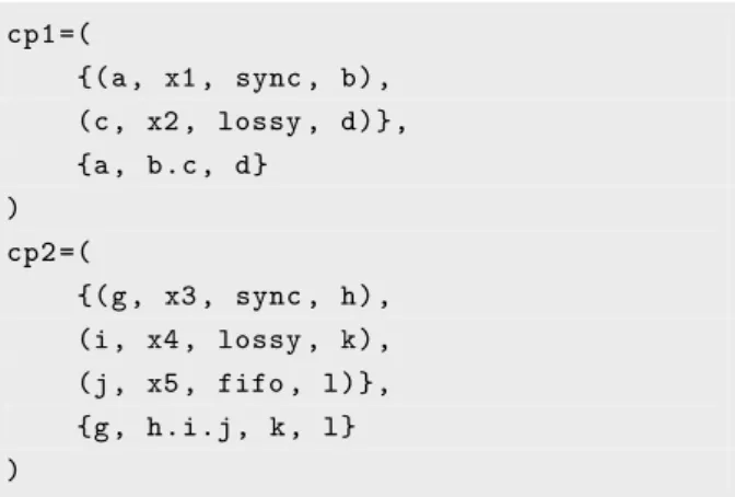
Figure 4 Reoautomata for primitive Reo channels and thesequencer connector. 19 Figure 5 Two simple coordination patterns. . . 33
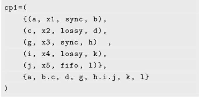
Figure 6 Resulting coordination pattern after applying theparprimitive. . . 34
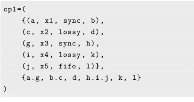
Figure 7 Resulting coordination pattern after applying thejoin primitive. . . . 35
Figure 8 Resulting coordination pattern after applying thesplitprimitive. . . 35
Figure 9 Resulting coordination pattern after applying theremoveprimitive. . . 36
Figure 10 Reconfiguration patterns.. . . 36
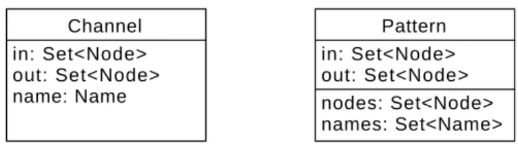
Figure 11 Internal representation of structured data types. . . 41
Figure 12 The compiler scheme. . . 48
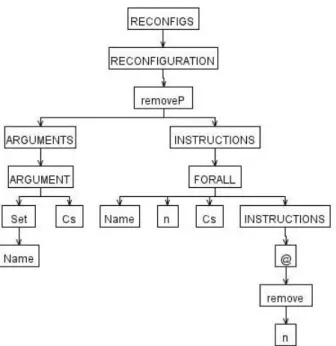
Figure 13 The removeP AST. . . 51
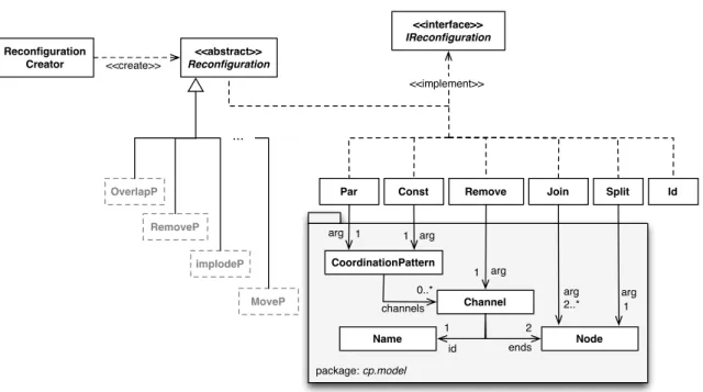
Figure 14 The Reconfiguration Engine model . . . 59
Figure 15 Example of aReCooPLa reconfiguration translated. . . 63
Figure 16 The User update coordination pattern. . . 64
Figure 17 The User update coordination pattern reconfigured. . . 65
Figure 18 The System high-level architecture. . . 66
Figure 19 Annotations and problem markers on the editor.. . . 67
Figure 20 Patterns Created View as part of the editor. . . 68
Figure 21 File dialog to save created patterns. . . 68
Figure 22 Originalcoordination pattern. . . 71
Figure 23 ExRoutercoordination pattern. . . 71
Figure 24 ReCooPLa implementation of thescaled-out reconfiguration. . . 72
Figure 25 ReCooPLa implementation of three reconfigurations.. . . 73
Figure 26 PartialRTS for the design of the Adaptable-ASK system. . . 73
Table 2 Mapping between theReCooPLastructured data types and the Recon-figuration Engine classes . . . 59 Table 3 Translation rules forReCooPLa constructs . . . 61
4.1 EBNF notation for thereconfiguration production. . . 40
4.2 EBNF notation for thedatatype production. . . 41
4.3 EBNF notation for theforall production. . . 42
4.4 EBNF notation for thereconfiguration_apply production. . . 42
4.5 EBNF notation for theconstructor production. . . 42
4.6 Constructors input example.. . . 43
4.7 EBNF notation for theoperation and attribute_call productions . . . 43
4.8 ReCooPLainput example. . . 44
4.9 EBNF notation for themain production.. . . 45
4.10 EBNF notation for themain_instruction production. . . 45
4.11 Main reconfiguration in ReCooPLa . . . 46
4.12 Parseroptions section. . . 49
4.13 Tree operators example. . . 49
4.14 Rewrite rules example. . . 49
4.15 Tokens section in parser. . . 50
4.16 Rewrite rules using created tokens. . . 50
4.17 Tree grammar optionssection. . . 51
4.18 Identifiers table forremoveP reconfiguration. . . 52
4.19 Example of the scope of a production. . . 53
4.20 Error reporting example.. . . 54
4.21 Error message example. . . 54
4.22 emitErrorMessagemethod rewriting. . . 55
5.1 Template for the Reconfiguration classes. . . 62
5.2 Template usage.. . . 62
5.3 Collection to save the result of the translation. . . 63
5.4 implodePreconfiguration pattern. . . 64
ABT Abstract Behaviour Types. 14
ADL Architecture Description Language. 6,12,26,28–31, 77
ADR Architectural Design Rewriting. 26 AML Architectural Modification Language. 31 ANTLR ANother Tool for Language Recognition. 46,47 ARC Actor, Role and Coordinator. 10–12,14
ASK Access Society’s Knowledge. v,6,69–73 AST Abstract Syntax Tree. 48–50,52,53,62 BIP Behaviour-Interaction-Priority. 12,27 CA Constraint Automata. 17–20,32
CASM Constraint Automata with State Memory. 18 CFG Context-Free Grammar. 47
CRM Customer Relationship Management. 64 DMS Document Management System. 64
DSL Domain Specific Language. 5,28,39,75,76 EBNF Extended Backus–Naur Form. ix,40–43,45 ECT Extensible Coordination Tools. 18,31,32,75 EQ Execution-Queue. 70
ERP Enterprise Resource Planner. 64 GUI Graphical User Interface. 31 HRE HandleRequestExecution. 70,71
IWIM Idealised Worker Idealised Manager. 9,14 JVM Java Virtual Machine. 59
ODE Open Distributed and Embedded. 10 PBRD Policy-based RRD. 12,14
QoS Quality of Service. 3,4,23,26 ROAD Role-Oriented Adaptive Design. 11 RRD Reflective Russian Dolls. 11,12,14 RRR Report, Recover and Resume. 54
RTS Reconfiguration Transition System. v,69,70,72,73 SA Software Architecture. 24–26,28,31
SaaS Software as a Service. 3
SCA Service Component Architecture. 28,31 SOA Service-Oriented Architectures. c,3,4,23,64 TS Training Server. 64
1
I N T R O D U C T I O NCloud computing is a recent paradigm based on three computational layers: infrastructure, platform and software [BBG11]. These are provided as services by some organisations, and their main objective is to provide high performance while keeping low degradation of Quality of Service (QoS). This intrinsic objective of cloud computing is achieved by its main char-acteristic — the elasticity — which is responsible for the provision of the right amount of computational resources to the real-time demands of a software system. This sensation of in-finite computational power and its need by the emerging software intensive systems, installed a shift in the software development. Software developed to and deployed in the cloud inherits its high performance, and is made available as a service (e.g., Google Docs). Thus,Software as a Service (SaaS) deliver, over the web, a service to the end-users, regardless of their location, which allows activities to be managed from central locations in a “one-to-many” model.
A service, in this context, is a loosely-coupled entity that offers some specific computational functionality via published interfaces (APIs). A single service may result from the composition of several other services that interact with each other, while completely unaware of their surroundings. This notion of service and computation by interaction, gave rise to the adoption ofService-Oriented Architectures (SOA)as the architectural style underlying modern software systems [Erl09]. SOAsare then based on services often distributed by different organisations, agnostic of programming language and deployment platform and are coordinated to provide a desired functionality. Coordination of services (or the definition of their interaction protocols) is usually kept in a layer separated from their internal functionality. Such coordination follows protocols (or interaction policies) that may be encapsulated, for instance, using connectors and are usually established at design time [Arb04]. However, SOAs are flexible, reliable and naturally dynamic: although policies are pre-established, services may be discovered and bound to the architecture only at runtime, rather than fixed at design time [FL13]. Dynamic bound of services is deeply related withQoSneeds. Thus, in an environment where change is the rule rather than the exception (e.g., the cloud), keepingQoS levels above some quality contracted is essential and, in general, entails the need for reconfigurations such as the dynamic binding/unbinding of services. But system requirements (whether they are functional or non-functional) also change during the lifetime of a system, and therefore, changing the way services interact play an important role to this end. For instance, considering a simple
interaction of services with a channel which has buffering capacity representing a queue of requests; if we do a minor change on it such as append an additional channel (with same capacity), we might improve substantially the whole system; in this case, the change will allow enqueue more requests.
Reconfigurations in aSOAsystem usually targets the manipulation of services or the inter-action protocols themselves. In the former, reconfigurations consist on the dynamic update of service functionality, substitution of services with compatible interfaces (but not necessarily the same behaviour) or removal of services [RC10,OMT98, HP06, MB08,SMR+11]. In the
latter, a reconfiguration is morelow-level and target the way services interact with each other. This sort of reconfigurations usually substitute, add or remove the components of the inter-action (e.g., communication channels), move communication interfaces between components and may even rearrange a complex interaction structure [Kra11,KMLA11a].
This dissertation intends to deliver a formal framework for modelling, reasoning and analys-ing coordination reconfigurations in the context ofSOAand cloud-computing, and it springs from a project that aims at studying reconfiguration of a system architecture [OB13a,OB13b].
1.1 statement of the problem
To assess the consequences of applying changes in a system beforehand is an ultimate re-quirement for SOA design. Software systems should adapt, at runtime, in order to meet new requirements and environmental conditions to maintaining, for instance,QoS levels, as initially agreed with the system consumers. In particular, this may lead to a need for change in the way services interact with each other.
In the last few decades, a number of (coordination) models have been designed, developed and presented to abstract and encapsulate the details of communication between services. All these models claim to provide a framework which enhances modularity, interoperability and reuse of components. However, they differ from each other in the definition of coordination, what is being coordinated and how coordination is achieved. They can be roughly divided, by the type of coordination they provide, in two categories: endogenous and exogenous. The main difference lies on the separation (or not) of the coordination and computation layers. In the former exists a mixture of coordination and computation code within a process definition. In the latter, on the other hand, there is a separation of concerns between coordination and computation. Linda [CG89] and Bonita [RW97] are examples of endogenous coordination models whereas Manifold [AHS93], ROAD [CH05] andReo[Arb04] are examples of exogenous coordination models. Coordination can also be seen on two other perspectives in the context ofSOA: orchestration (where components are coordinated without knowing each other) and choreography (where components are coordinated taking into consideration each other).
However, there is a lack of rigorous (formal) methods to correctly design and analyse (coordination-based) reconfigurations. In [OB13b], a formal model in which connectors are represented by a graph of communication channels is introduced. The graph nodes stand for interaction ports, where a subset of them constitute an interface for plugging concrete services or other coordination graphs; and edges are labelled with channel identifiers and types defining their behaviour. Such graphs are referred to as coordination patterns. A co-ordination pattern encodes a reusable solution for an architectural (coco-ordination) problem, which is the description of interaction defined to answer to a set of requirements or con-straints. In [OB13a] reconfiguration mechanisms to actuate over such patterns are proposed. In this setting, reconfigurations are defined as a combination of elementary reconfiguration primitives. The application of a reconfiguration to a coordination pattern yields a new co-ordination pattern. Moreover, formal verification of requirements enclosed in such patterns and classification/organisation of reconfigurations are given as features of the framework dis-cussed in [OB13a,OB13b]. But to express and apply reconfigurations, in practice, is not yet incorporated in such a framework, hindering its applicability. Thus, the following research question arises: How to simulate a reconfiguration at system design time?
1.2 objectives
This dissertation aims at developing a tool for rapid prototyping of coordination-based ar-chitectural reconfigurations. This involves several tasks: design of a language to express reconfigurations, through combination of primitive operations; development of a language processor that should report errors from syntactic and semantic analysis; and development of an engine for reconfigurations (based on the language), as an eclipse plugin, to model and simulate reconfigurations of service coordination protocols.
The first task implies the design of a Domain Specific Language (DSL) – referred as Re-CooPLa – that supports the model presented in [OB13a] and makes it a suitable tool for the software architect. ReCooPLa provides a precise, high-level interface for the software architecture to plan and experiment with reconfiguration strategies. Tailored to the area of architectural reconfigurations, it makes possible to abstract away from specific details, such as the effect of each primitive operation and their actual application, as well as to hide their actual computation under a processor. The second task encompasses a few steps which ensure that the specification is syntactically and semantically correct. These “steps” follow the tradi-tional approach for compiler construction [ASU86] and include a Lexer, a Parser, a Semantic Analyser as well as a Translator to obtain the necessary executable format. Finally, the last task is developed in Java. Thus, as it often happens with DSLs, the design language must be first translated into a subset of Java (by the language processor), which should be then recognised and executed by an engine. The engine execute coordination-based
reconfigura-tions specified in the design language, and apply them to coordination patterns, which are in turn defined inCooPLa [ROB14b], a lightweight language to define the graph-like structure of coordination patterns. In addition, the reconfiguration primitives described in [OB13a] as elementary operations, are also implemented in Java, to support the reconfiguration engine.
A suitable case study to test the reconfiguration engine is created. It is also intended to make the engine part of the Eclipse Coordination Tools [AKM+08], a fairly known platform
for design and verification of Reobased coordination.
1.3 dissemination
During the research period a paper [ROB14a] named “ReCooPLa: a DSL for coordination-based reconfiguration of software architectures” was written, submitted and accepted in an international conference: the 3rd Symposium on Languages, Applications and Technologies (SLATE’14). This paper was invited for extension by the ComSIS journal 1, which has a 2
years impact factor of 0.549. Thus, a new paper [ROB14b] named “Towards an engine for coordination-based architectural reconfigurations” has emerged. This paper was also already submitted and is waiting for acceptance.
All information concerning the reconfiguration engine is also accessible in the project web-site2.
1.4 document structure
The state of the art of this work is subdivided in two chapters: Chapter2and Chapter3. The former reviews some coordination models, giving emphasis to theReocoordination model and its formal models. Chapter3addresses reconfigurations in Software Architectures and, in par-ticular, coordination based reconfigurations. Tools and languages, namelyADL, that already exist to support the reconfigurations and their analysis are also presented in this chapter. In addiction, the reconfiguration framework is also introduced by the end of this chapter, by ad-dressing coordination protocols and coordination-based reconfigurations (e.g., reconfiguration patterns). In Chapter4, the language developed for processing reconfigurations, as well as the respective processor and the supporting technologies, are presented and described. Chapter5 describes the Reconfiguration Engine by presenting its model, architecture and development. Furthermore, a set of translation rules is presented and their implementation described in this chapter. Chapter 6 presents a case study in the context of self-adaptive systems, featuring the ASK system. Finally, Chapter 7 concludes the dissertation and raises some issues for future work.
1 http://www.comsis.org/indexing.php
2
B A C K G R O U N D : C O O R D I N AT I O N M O D E L SThis chapter presents an overview of coordination through a set of distinct coordination models. The Reocoordination model receives particular attention due to its relevance to this work. Some formal models forReo are also presented.
2.1 coordination
The increase of computational resources has allowed the development of new programming paradigms based on distributed and parallel systems, which are able to, for instance, perform tasks faster and be fault tolerant. This led to the design and implementation of more com-plex applications and systems such as telecommunication networks, peer-to-peer networks, distributed databases, real-time process control (e.g., aircraft control systems) and parallel computation.
The emergence of these systems drew attention to issues such as reusability, compositional-lity and extensibicompositional-lity [PA98]. In order to deal with them and provide interoperation between systems, a blend of language models becomes necessary.
Coordination offers an alternative to mitigate the problems and address some of the issues that arise with the development of complex distributed and parallel computer systems [PA98, Arb98].
Actually, a programming model can be built through the combination of two distinct pieces: the computation model (processes involved in manipulating data) and the coordination model (responsible for the communication between the processes) [GC92,PA98]. According to Gel-ernter and Carriero [GC92], a coordination model is “the glue that binds separate activities into an ensemble”.
Coordination models are defined by three main components: coordination entities (e.g., threads, users, etc), coordination media (e.g., channels, tuple spaces, etc) and coordina-tion laws (e.g., enact either synchronous or asynchronous behaviours for coordination en-tities) [Cia96]. A coordination model can be embedded either in a coordination architecture (e.g., client-server architecture) or in a coordination language. A coordination language is
“the linguistic embodiment of a coordination model” [GC92]. It provides operations to create computational activities and support communication between them.
All coordination models claim to provide a framework which enhances modularity, inter-operability and reuse of components. They differ from each other in the definition of what is being coordinated and how coordination is achieved.
2.1.1 Overview of coordination models
Papadopoulos and Arbab [PA98] argue that coordination models and languages can be clas-sified asdata-driven orcontrol-driven. Briefly, in the former exists a mixture of coordination and computation code within a process definition whereas in the latter there is a separation of coordination from computational concerns. In the data-driven category, coordination tends to be endogenous and is usually provided as a set of primitives which is mixed within some “host” computational language (i.e., embedded within computational entities). This category is mostly used for parallelising computational problems and coordinating manipulated data. On the other hand, in the control-driven category, coordination tends to be exogenous and is usually delivery as a language by itself (i.e., isolated from computational entities). This category is mainly used for modelling systems and coordinating entities, such as system com-ponents, since the structure and contents of data is of minor or no importance in it. Whereas in the data-driven category coordinator processes directly handle and examine data values, in the control-driven category processes are treated as black-boxes, whether coordination or com-putational processes, and therefore the communication of processes with their environment is achieved through well-defined interfaces (input and output ports).
Most of the coordination models in the data-driven category are deeply related to the notion of aShared Data-space. This is a language paradigm in which computations are performed using a content-addressable communication medium with a tuple-like representation [RC90].
linda
Linda [CG89] is a data-driven and endogenous coordination language. It is based ongenerative communication: if two processes need to communicate, the data producing process generates a new data object, referred to as a tuple; on the other hand, to create processes (e.g., a process needs to create a second one) the so-called “live tuple” is first generated and then also turned into an ordinary data object tuple. In both cases, the tuple is stored in a shared data-space calledtuple-space. Then, herein the receiver can access the new tuple.
Linda offers very simple coordination entities (active and passive tuples, which represent processes and messages, respectively), a unique coordination medium (tuple-space), and a small number of coordination laws (embedded in four primitives only). The active tuples
representing processes in tuple space are turned into ordinary passive tuples right after the completion of their execution.
The small set of coordination primitives provided by Linda to perform operations on the tuples and tuple-space are: in(t), out(t), rd(t) and eval(p); where t stands for tuple and p for process. The in(t) primitive retrieves a passive tuple t (i.e., atomically reads and consumes a tuple) from the tuple-space. On the other hand, the out(t)primitive puts a passive tupletin the tuple-space. Therd(t)primitive retrieves a copy of passive tuplet(i.e., non-destructively reads a tuple) from the tuple-space. Lastly, eval(p) puts an active tuple (i.e., a process p) in the tuple-space. While the out and eval primitives are non-blocking primitives, the in and rd are blocking primitives and thus will suspend execution until the desired tuple be found. If more than one tuple in the tuple-space matches, then one is selected non-deterministically. However, these primitives also have non-blocking forms (inpand rdp) which do not block if the required tuple is not found.
Linda is designed to be coupled with a host programming language and their primitives are independent of this host language. There are many implementations and extensions of Linda such as TSpaces (IBM) [WMLF98], JavaSpaces (Oracle) [FAH99], Bauhaus Linda [CGZ95], LAURA [Tol96], Bonita [RW97] and LIME [PMR99] to name but a few. They are developed using many host languages (C, Lisp, Pascal, Prolog, Java, etc) and paradigms (imperative, functional, object-oriented, etc) [ACG86,CG89].
manifold
Manifold [AHS93, Arb96b, Arb98] is a control-driven and exogenous coordination language that models external components as processes. This language is based on theIdealised Worker Idealised Manager (IWIM) [Arb96a] model, which is an abstract model of communication (through broadcast of events or point-to-point channel connections) that “supports the separ-ation of responsibilities and encourages a weak dependence of processes on their environment”. In other words,IWIMis focused on the separation of concerns (computation concerns isolated from the communication ones) and anonymous communication (processes that intercommu-nicate without knowing each other). This separation, along with the higher-level abstractions, improve software productivity, maintainability, modularity, and even reusability.
Manifold is a strongly-typed, block-structured and event-driven language. Thus, the only control structure that exists in it is an event-driven state transition mechanism and its entities are events, processes, ports and streams (asynchronous channels). The Manifold events are used purely for triggering state changes and do not carry data. In turn, a process is a black-box component with well defined ports, connected between themselves by means of streams. These processes are called Manifold coordinators which are, similarly to the most of the other control-driven coordination languages, clearly distinguished from computational processes.
The Manifold system runs on multiple platforms and consists of a compiler, a runtime system library, a number of utility programs, and libraries of built-in processes. Furthermore, Manifold has a visual programming environment called Visifold [BA96].
arc
In the past few decades, well-defined mathematical abstractions for concurrent computation in a distributed environment such as CSP [Hoa78], π-Calculus [MPW92], and the Actor model [Agh86] have been studied. The latter is used by the Actor, Role and Coordinator (ARC) coordination model to model the concurrent computational part of an Open Distrib-uted and Embedded (ODE)system. In addition, to deal with the coerced coordination part of anODEsystem, theARCmodel introduces the concept of a role that provides an abstrac-tion for coordinated behaviours, which in turn may be shared by multiple concurrent entities calledactors. TheARCmodel [RYC+06] is described by the authors as a “role-based
decent-ralised coordination model for ODE systems” that intends to better address the dynamicity and scalability issues inherent inODEsystems while fulfilling the system’sQoSrequirements. These requirements are mapped to coordination constraints and imposed on actors through message manipulations, which are carried out by roles and coordinators – the coordination entities.
Furthermore, theARCmodel can be seen as the composition of three layers, related to each of the components of the model: actor layer, role layer and coordinator layer. The actor layer is dedicated to functional behaviour and is independent from the coordination (composed by the role and coordinator layers) which is exogenous and imposes the above mentioned QoS
constraints among the actors, preserving the semantics of the original model [Agh86]. The actors – the computation entities – are single-threaded active objects which communicate with each other only through asynchronous messages [SR11]. They have states and behaviours which can only be changed by themselves while processing a message. An actor can perform only three atomic primitive operations: createnew actors,send messages to other actors and become, while processing a message, to the actor assume a new state and behaviour. The coordinators on the coordinator layer are responsible for the coordination among roles. The role layer lies between the actor and coordinator layers and therefore acts as a bridge between these two layers. A role may enable the coordination of a set of actors without requiring the coordinator to have an accurate knowledge of the actors that play the role. A role can also be seen as an active coordinator that manipulates the message sent and received by the actor. In addition, a role may generate events (viewable by coordinators) and change its state. In short, just as actors react to messages, roles and coordinators react to events. Due to the introduction of roles, the coordination is divided into inter-role and intra-role coordination, which are the responsibility of coordinators and roles, respectively. This allows a better separation of concerns and reduces the complexity of the entities. Roles and coordinators
themselves can be viewed as meta-actors and react to meta-messages and actor events. The role meta-actors are able to observe and manipulate messages in the actor layer.
road
TheRole-Oriented Adaptive Design (ROAD)[CH05] framework is a control-driven coordina-tion model that extends work on object-oriented role and associative modelling [KO96,Ken00]. This model targets scalability issues of concurrent and distributed systems through a role-based coordination model. Similarly to the ARCmodel, the elements being coordinated are roles, which can be added to, and removed from, objects. These roles also abstract coordina-tion behaviours among the objects that play them. However, they have different definicoordina-tions. Kristensen and Osterbye [KO96] provide a definition of roles based on the distinction between intrinsic and extrinsic members of an object. Intrinsic members provide the core functional-ity – i.e., the computational and communication capabilities – of the object, while extrinsic members (methods and data) contain the functionality of the role.
The ROAD approach to create adaptive software systems is based on the distinction between functional and management roles. Functional roles are focused on achieving the desired application-domain output and constitute the process as opposed to the control of the system. Since functional roles do not directly reference each other, they are associated by contracts that mediate the interactions between them. In turn, the creation and monitoring of these contracts is the responsibility of a concrete type of management role: the “organiser” role.
ROADcontracts are association classes that express the mutual obligations and interactions of the contract “parties” (i.e., modules or processes) to each other. Similarly to roles, con-tracts have management and domain function levels. Management concon-tracts specify the type of communication acts and protocols that are permissible between the two parties whereas functional contracts specify, among other things, the performance obligations and inherit control relationships from these management contracts.
pbrd
TheReflective Russian Dolls (RRD)[MT02] is a model of reflective distributed object compu-tation, based on rewriting logic. Rewriting logic [Mes92] is a formalism designed for modelling and reasoning about concurrent and distributed systems. Its states are represented as ele-ments of an algebraic data type and behaviour is given by local transitions between states described by rewrite rules.
The RRDmodel uses reflection and hierarchical structure to provide a layered exogenous coordination model, wherein each layer controls the communication and the execution of objects, i.e., coordinators, in the layer below. A coordinator has an attribute that holds a nested configuration of objects and messages and its behaviour is specified by rewrite rules.
These rules also control delivery of messages in the configuration of a coordinator and specify how peer-to-peer messages are processed.
Policy-based RRD (PBRD)[Tal06] is a restricted form ofRRDin which communication con-trol is specified by declarative policies to, for instance, ordering of message delivery, serialising requests and recording a history of events. It is focused on logical communication constraints. Similarly to the ARC model and based on the actor model of computation [Agh86], the ob-jects coordinated inPBRD are actors and the coordinators are meta-actors [TSR11]. These actors communicate by asynchronous message passing and encapsulate their state and thread of control. On the other hand, requirements of the coordinators are specified by informal constraints on the resulting interactions of the coordinated actors.
bip
Basu et al. [BBS06] introduced theBehaviour-Interaction-Priority (BIP) language for model-ling heterogeneous real-time components. It supports the construction of hierarchically struc-tured components from atomic components characterised by their behaviour and interfaces. These components are obtained through the overlap of three layers: the lower one describes behaviour; the middle layer models interactions between components, specified by a set of connectors; and the upper layer is a set of priority rules (describing scheduling policies for interactions). Any combination of behaviour, interaction and priority models meaningfully defines a component. The connectors are used by the language to specify possible interac-tions between components and priorities. Interacinterac-tions express synchronisation constraints between the composed activities of the components and priorities filter possible interactions to guide system evolution in order to address the performance requirements. The combina-tion of interaccombina-tions and priorities defines an abstract concept of architecture separate from behaviour.
BIPuses a parameterised binary composition operator on components, which allows incre-mental construction,i.e., obtaining a compound component by successive composition of its constituents. The language also provides a powerful mechanism for structuring interactions involving strong (rendezvous) or weak (broadcast) synchronisation.
In contrast with other component frameworks, BIP executes atomic components concur-rently and coordinates them in terms of high-level mechanisms such as protocols and schedul-ing policies [BBB+11]. Since this language focuses on the organisation of computation between
components, it can be viewed as anADL (see Section3.3).
orc
Orc [Mis05] is a coordination model, focused on the paradigm of orchestration that supports a structured model of concurrent and distributed programming. This model introduces the concept of a site as a basic (web) service, such as sequential computation or data
manipu-lation. It also provides constructs to orchestrate concurrent invocation of sites in order to managing time-outs, delays and failure of components and communication. Orc is highly asynchronous, naturally dynamic, based on ephemeral connections to services and deals well with failure [PC08].
An Orc program is composed by an expression with a set of definitions. An Orc expression can be a primitive site call, a reference to another expression, or a composition of expressions; and it is responsible for (dynamically) initiate contact with external sites. A site call is written asM(p), wherepis a tuple of arguments which can be constants or variables. Orc’s semantics is detailed in [Mis05].
Orc is built upon three composition operators for parallel computation, sequencing and selective pruning. This model represents a multi-threaded computation by an expression which has useful algebraic properties such as CSP [Hoa78] andπ-Calculus [MPW92]. However, unlike these, Orc permits integration of arbitrary components – the so-called sites – in a computation, which introduces a distinction between it and the environment in which it runs. Since Orc describes the structure of a distributed computation using primitives that define common communication patterns, the author [Mis05] argues that it may be a viable alternative to process calculi. This model can be applied in the development of workflow systems since, according the author, there is no commonly-accepted theory of workflow.
piccola
PICCOLA [ALSN01] is a composition language and a formal model for component-based application development that embodies the paradigm described by the authors as “Applic-ations = Components + Scripts”. In other words, applic“Applic-ations are seen as compositions of components, which are black-box entities that encapsulate services behind well-defined inter-faces whereas scripts encapsulate how the components are composed. Thus, it is made a clear separation of computational elements (i.e., components) and their coordination (i.e., scripts). This separations enhances the flexibility, extensibility, and maintainability of an application.
PICCOLA has a small syntax and a minimal set of features needed for specifying different styles of software composition. Its constructs are translated into the πL-calculus [Lum99] – polymorphic variant of the π-calculus [MPW92]. A component is regarded as a set of interconnected agents used to model coordination abstractions. Its interface is represented as a form, which is a special notion of extensible and labeled records, used to model extensible interfaces and contexts. These agents communicate with each other by sendingformsthrough private channels instead of tuples. In fact, agents and forms are the foundation of this composition language since they provide a good basis for specifying higher-level components and connectors.
Despite the fact that the natural type of interaction described by theπL-calculus is directed channel communication, PICCOLA defines also language constructs to simplify the encoding
of other types of interaction such as event based communication or failures. These constructs are functions, infix operators to support an algebraic notion of architectural style, and the explicit notion of a (dynamic) context to encapsulate required services.
PICCOLA has a syntax similar to that of Python and Haskell and thus newlines and indentation, for instance, are used rather than braces or end statements to delimit forms or blocks. Forms, however, may also be specified on a single line by using commas and brackets as separators. This language was implemented in Java and a gateway interface was also defined in order to use external components into the PICCOLA system. The reflection package of Java was used internally to embed arbitrary Java objects into PICCOLA scripts. In turn, this scrips can be embedded into stand-alone Java applications, applets or servlets.
2.1.2 TheReo coordination model
Reo [Arb04] is a channel-based exogenous coordination model which defines the primitive operations that allow for composition of channels into complex connectors.
Some of the models previously presented are highly expressive but theReo model is more mature, with several formal semantics and tools for analysis. This model is highlighted in this work since it is the chosen one to describe the associated semantics of the reconfiguration framework, presented in Section3.5, which in turn is supported by ReCooPLa.
The word “exogenous” means “from outside”, so exogenous coordination means coordina-tion from outside. Thus, Reo separates the computation layer from the coordination layer. The Reo model, similarly to other control-driven models, isolate coordination by consider-ing functional entities as black boxes [SR11]. Reo extend the IWIM [Arb96a] model (see Manifold description in previous section) by treating both computation and coordination components as composableAbstract Behaviour Types (ABT), which is, as well as IWIM, a two-level control-driven coordination model where computation and coordination concerns are achieved in separate and independent levels. Coordination inReo is abstracted as aReo cir-cuit specified by, for instance, a constraint automaton [BSAR06], while in thePBRD[Tal06] model coordinations are described as informal rule specifications on the resulting interactions of coordinated actors. Reo is closer to being a programming model, while RRD – briefly presented before, along with the PBRD model – focuses on more abstract specifications. A detailed comparison among theReo,PBRD, and ARCmodel can be found in [TSR11].
A connector in Reo explicitly represents an interaction between architectural components and acts as “glue-code” that connects these components and coordinates their activities in a component-based architecture. Formally, a connector is defined as a graph of channels whose nodes represent interaction points and channels have a behaviour that imposes a coordination policy between two points.
Connectors are bound to each other using their interfaces, which are defined by their bound-ary channel ends. A connector can perform I/O operations —writeandtake— on these ends. It is by synchronising these operations that coordination is achieved [CCA07].
channels
Channels constitute the primitive connectors in Reo. Each channel is defined as a medium of communication with exactly two ends and a specific behaviour [Arb04]. Each channel end can be a source or a sink end. The former accepts data into its channel and the latter expels data out of its channel. Usually, a channel is directed, i.e., have a source and a sink end, but
Reo also accepts undirected channels, which have two ends of the same type.
Reo presents a plethora of primitive channels, offering different synchronisation, buffering, lossy and even directionality policies. Figure1recalls the basic channels used inReothat can be used to built more complex connectors.
sync lossy drain fifoe
• fifof Figure 1: Primitive Reo channels.
A channel can perform awriteof some data on a source end, or a takeon a sink end. The write/takewill succeed when the connector either accepts the data from a writer component, or makes available data for a reader component.
Async channel has a source and a sink end. This channel transmits data from one end to another whenever there is a request at both ends synchronously, otherwise one request shall wait for the other. Thus, this blocks awrite operation on its source end or atake operation on its sink end, as necessary, to ensure that these two operations succeed synchronously.
Thelossy channel behaves likewise, but data may be lost whenever a request at the source end is not matched by another one at the sink end. Thus, all write operations on its source end are immediately succeed, which means that if exists a pending takeon its sink end, data will be transferred, otherwise the write operation succeeds but data will be lost.
The synchronousdrain channel accepts data synchronously at both ends and loses it, since it has two source ends and does not have any sink end. Thus, it is not possible to take any data out of this channel, since all data entering is lost, when the operations on both source ends are synchronised.
The fifo channel has a buffering capacity of one memory position, therefore allowing for asynchronous occurrence of I/O requests. Qualifiereorf refers to the channel internal state, which can beemptyorfull, respectively. If the buffer is empty: awriteoperation on its source end succeeds, and fills the buffer; a take operation on its sink end is delayed until buffer is
full. Then, if the buffer is full: atakeoperation on its sink end succeeds and removes the data from the buffer; a writeoperation on its source end is delayed until buffer is empty again.
In Reo, channels can be joined together by their ends. The junction of ends defines nodes, and altogether (channels and nodes) define complex coordination structures called connectors. nodes
A node is composed of (one or more) channel ends, and are classified into three different types: source, sink or mixed node. The node type depends on the type of their coincident channel ends. If a node connects only source channel ends, it is classified as a source node. On the other hand, if it connects only sink channel ends, it is classified as a sink node. Finally, if it connects both kinds of channel ends, it is classified as a mixed node.
A node acts as asynchronous replicator when it connects more than one outgoing channel. It replicates data to all outgoing channels, when awrite operation can be performed in all of them, synchronously.
On the other hand, a sink node acts as a non-deterministic merger when it connects more than one incoming channel. It merges data from the incoming channels, when at least one of them offers data (i.e., a take can be performed). In particular, if more than one channel offers data, only one of them is selected non-deterministically, i.e., data is randomly chosen from one of the channels with fairness.
A a mixed node combines both behaviour by consuming data from one of its sink ends and replicating it to all source ends.
connectors
In Reo, connectors are built from channels and nodes and have an interface, or interaction points, that correspond to a set of source and sink nodes. These connectors are entities that provide the “glue-code” for coordinating the interactions between architectural components. In Figures2 depict two examples of connectors.
a b o1 o2 cde f gh (a) a b c l m j k (b)
Figure 2:Reoconnectors: (a)Sequencer and (b)Exclusive Router
Figure 2 (a) presents a Sequencer connector composed by four sync and one fifo channels connected together. Graphically, white circles represent the connector interface, i.e., source or sink nodes. In turn, black ones represent mixed (internal) nodes.
This connector implements a generic sequencing protocol that can be parameterised to have as many nodes as required, by inserting more sync and fifochannel pairs [Arb04].
Figure2(b) shows anExclusive Router connector that accepts data on its source node (a), and depending on the context (i.e., depending on the existence of requests in one of the sink ends), routes data synchronously to one of its two sink nodes (borc).
If both sink nodes are able to accept data, only one of them is selected non-deterministically. This is due to the fact that nodekmerges its inputs without priority,i.e., exactly one of the sync channels is activated, replicating data on the active side to the corresponding sink node (borc); the data item on the other side is destroyed by its lossy channel [AKM+08,Kra11].
2.1.3 Formal models of Reo
In the last decade, many semantic formalisms for describing the behaviour of Reoconnectors have emerged, including coalgebraic models, operational models, and models based on graph-colouring. [JA12] presents an overview of the existing semantic formalisms for modellingReo
connectors.
In this section, we will focus on three of the most adopted models: Constraint Auto-mata [BSAR06], Reo Automata [BCS12] and Connector Colouring model [CCA07].
constraint automata
Baier et al.[BSAR06] introduce an operational model for Reo called Constraint Automata (CA), to describe the behaviour and possible data flow in coordination models that connect anonymous entities to enable their coordinated interaction. CA yields a foundation for the formal verification of coordination mechanisms, i.e., conceptual generalisations of automata where data constraints,i.e. boolean expressions for the data values, influence applicable state transitions. The automata states stand for the possible configurations (e.g., the contents of the fifo channels of a Reo connector) while the automata transitions represent the possible data flow and its effect on these configurations,i.e. the set of ports enabled and its constraints.
The constraint automaton of a given Reo connector is defined in a compositional way: CA defines the Reo primitive channels, and through application of join and hide operations compose them to devise the behaviour of a complex connector.
The constraint automata corresponding to the Reo channels (sync, lossy, drain and fifo), as well as two connectors (Sequencer and Exclusive Router), can be seen in Figure 3. The transitions of constraint automata are labeled with pairs consisting of a non-empty subset N of {A1, ...,An} and a data constraint g. Data constraints can be viewed as a symbolic
representation of sets of data-assignments. Formally, data constraints are propositional for-mulae built from the atoms “dA = d′′ where data item d is assigned to port A. The most
commonly used boolean connectors are ∧ (conjunction), ⊕ (exclusive or), → (implication) and ↔(equivalence). q {a,b},db=da Sync q {a,b},db=da {a} Lossy q {a,b} Drain p q(x) {a},x=da {b},db=x Fifo ex fx {a,o1},do1=da∧dx=da {b,o2},db=dx∧do2=dx Sequencer q {a,b},db=da {a,c},dc=da ExclusiveRouter
Figure 3: Constraint automata for primitive Reochannels and two connectors.
The semantics of Reoconnectors can also be given usingConstraint Automata with State Memory (CASM)[PSHA12]. There are several variations of ordinary CA and CASM is one of them [JA12]. In CASM, communication and synchronisation is realised using port names, and states can be enriched with local memory cells, which can be seen as finite representation of data elements. These automata derive executable coordinator models from connectors (e.g., as generated Java code) in theReoimplementation, using the Extensible Coordination Tools (ECT)[Kra11], presented in the section 3.4.
Notions of bisimulation equivalence and a simulation relation forCAthat provide methods for checking language equivalence or language inclusion for non-deterministic automata are also introduced in [BSAR06].
In their basic form, CA cannot express context dependency. Context dependency en-ables connectors to be more responsive to changes in their environment, and can express, for instance, the priority of one behaviour over another. InCA, for instance, the constraint automaton corresponding tolossyReochannelc.f., Figure3, allows data to be lost regardless of the context, i.e., irrespective of the existence or not of a request (take) on sink end, thus misinterpreting the intended operational semantics.
reo automata
Bonsangue et al. [BCS12] introduce a new automata-based semantic model for expressing context-dependentReo connectors, called Reo Automata. This model took into account the failures and benefits of previous automata-based approaches such asCA[BSAR06], to provide a behavioural description of Reo connectors. The Reo automata corresponding to primitive channels are very compact and intuitive, with a small number of states and transitions, com-paratively to other contemporary models [Cos10].
Reo Automata extend the notion of context-dependent automata to include the modelling of data flow, as inCA. Reo automata overcomes theCAdeficient handling of context by explicitly modelling both the presence and absence of requests on the channel ends, which means that data can only be lost, in a lossychannel sink end, if a request does not exist on it. Thus, this extra information correctly gives semantics to context-dependent channels and connectors, such as the lossy channel or the exclusive router connector, as can be seen in Figure 4. The Reo automata corresponding othersReochannels, as well as the sequencer connector, are also depicted in Figure 4. Intuitively, a Reo automaton is a non-deterministic automaton whose transitions have labels of the form g|f , where g is a guard (boolean condition) and f a set of nodes that fire synchronously. In addition, g can be used to describe the negation of g. A transition can be taken only when its guard g (or its negation) is true.
Each transition labeled by g|f satisfies two criteria: reactivity and uniformity. According the former, data flows only on nodes where a request is pending. The latter captures two properties: the request set corresponding precisely to the firing set is sufficient to cause firing; and removing additional unfired requests from a transition will not affect the (firing) behaviour of the connector [BCS12].
q ab|ab Sync q ab|ab ab|a Lossy q ab|ab Drain e f a|a b|b Fifo e fx ao1|ao1 bo2|bo2 Sequencer q abc|ab abc|ac ExclusiveRouter
Figure 4:Reoautomata for primitiveReochannels and thesequencer connector.
connector colouring
Clarke et al. [CCA07] present a semantic model based on connector colouring for resolving the context dependent synchronisation and mutual exclusion constraints required to determine the routing for data flow in Reo connectors. This model aims at facilitating the data flow computation (and implementation) of Reo connectors in a distributed computing environ-ment. It requires less mutual exclusion in a distributed implementation and does not require backtracking.
One aspect of the CA model is that transitions are labelled with the collection of nodes that synchronously succeed in a given step, at the exclusion of all other nodes present in the
connector being modelled. Calculating this set based on the configuration of a connector is precisely what connector colouring achieves. That is, the 2-colouring model of a connector produces a set of colourings which can be compared with the transitions in the corresponding CA. This set comprises a so-called flow and a no-flow colours. The former marks places in the connector where data flows, and the latter marks the absence of data flow.
Using 3-colouring model, the no-flow colour of 2-colouring model is replaced with two differentno-flowcolours to trace the exclusion constraints responsible for the no-flow back to their origins,i.e. provide information about the reason for the absence of data flow, allowing to properly model context-sensitive connectors.
The set of the 3-colouring model is Colour={————,− −◁− −,− −▷− −}.
Graphically, the arrow indicates the direction of exclusion, i.e. it points away from the exclusion reason and in the direction in which the exclusion propagates.
Connector colouring permits to capture context-dependent behaviour and therefore provide semantics to context-dependent connectors, by considering the context (the presence or ab-sence) of pending I/O operations at the ends of a connector. Thus, channels and other primitive connectors determine the actual data flow based on the colouring of their ends.
Each colouring of a connector is a solution to the synchronisation and exclusion constraints imposed by its channels and nodes.
In order to understand it better, let us present some primitive Reo channels using the 3-colouring model.
• sync channel
i)———— ii) − −▷− − iii) − −◁−−
In configuration i) data flows through the channel. In ii) data does not flow through the channel and the reason is given that a problem occurred in the input operation. Finally, in iii) data does not flow through the channel and the reason to delay relates to a problem occurred in the output operation.
• drain channel
i)———— ii) − −▷− − iii) − −◁− −
The configurations are the same as for the previous channel, however with a slightly different meaning on ii) and iii). In the former data flow is delayed due to a problem in the input operation at the left source end, and in the latter, the data flow is delayed due to a problem in the source end at the right.
• lossy channel
Configuration i) occurs when both source and sink end perform their I/O operations (writeandtake) synchronously. Inii), the input operation is performed, but the data is lost because there is no output operation at the sink node. The arrow pointing to the left propagates this reason to the point where data is lost. Iniii)the data does not flow because the input operation failed. The reason propagates into the direction of the sink node as if it was a signal to explain what happened at the other side of the channel. • fifo channel
i)—–−▷− ii) −▷− −▷− iii) −◁−—– iv) −◁− −◁−
This channel has four configurations: two for empty state plus two for full state. Ini) the input operation occurs, but the output operation does not, since the buffer is empty, and thus no output operation may occur. Inii)the input operation fails and the reason is propagated through the channel. In iii) the input operation is not performed since the buffer is full. Nevertheless the output operation is performed. In iv) the output operation is not performed, thus the buffer is still full and consequently the reason is propagated to inform the source end of the channel that an input operation should be delayed.
3
S TAT E O F T H E A RT R E V I E W : S O F T WA R E R E C O N F I G U R AT I O N SNowadays SOA is in focus mainly due to the services interoperability that this architectural style enables, regardless of the language in which each service was implemented or even the hardware in which it runs. The emergence of cloud-computing also had an important role to make SOAthe paradigm underlying modern software systems.
A major concern in these systems is to maintainQoSlevels, in particular, a continuous avail-ability of services. For this, and in order to adapt a system to new requirements, environments or failures [Per97,Wol97], their underlying architecture can be changed or reconfigured, either by dynamically updating service functionalities, substituting, adding or removing services; or, by changing the behaviour or structure of software connectors.
This chapter reviews the notion of reconfiguration in architectural design and introduces the specific reconfiguration model implemented in this MSc dissertation.
3.1 architectural reconfigurations
The architecture of a software system consists, basically, of a set of interconnected components and protocols that determine their interaction. In architecture design emerges the concept of architectural style [SG96], i.e., some set of rules indicating which components can be part of the architecture and how they can be properly interconnected.
Architectures usually are designed and changed in a static way by refining abstract com-ponents or assembling subsystem architectures. However, in some architectures namely in critical software systems, this might not be possible once stoping or even restarting a system for changes or updates leads to reducingQoSlevels and increasing costs and risks. Changes in the configuration of the architecture of a running system are called dynamic reconfigurations. Often, however, the facilities for runtime modification found in current operating systems, distributed object technologies, and programming languages, do not ensure the consistency, correctness, or desired properties of dynamic change [OMT98].
Dynamic software reconfiguration consists in changing the configuration of an architecture at runtime. Some distributed systems use functional redundancy or clustering in order to avoid the need for runtime change. Upgrades to web servers, for instance, are held by
for-warding incoming network traffic to a redundant host while the original host is reconfigured. However, due to the cost and even the risk that this approach implies, this is not always feasible.
Software Architectures (SAs) have the potential to provide a foundation for systematic runtime software modification and can support different types of software evolution, such as corrective, perfective, and adaptive evolution [GJM02].
Oreizy et al. [OMT98] present an architecture-based approach to runtime software evolution that operates at the architectural level. The main purpose of this approach is to reduce the costs and risks typically associated with dynamic reconfiguration. Other approaches to runtime software evolution have been proposed [GR91,GJB96,PHL97].
Gorlick and Razouk [GR91] present a data flow based approach to runtime change called Weaves. A weave is an arbitrary network of tool fragments connected together by transport services. In turn, each tool fragment is a small software component that performs a well-defined function and may retain state. However, Weaves does not provide a mechanism to check the consistency of runtime changes neither explicit support for representing change policies.
Grupta et al. [GJB96] describe an approach to modelling changes at the statement level for a simple abstract imperative programming language. In this approach, applications must be written entirely in the dynamic language to benefit from dynamism, which leads to a performance overhead since every function invocation must be bound during runtime. In addition, application behaviour and dynamism are not explicitly separated.
Peterson et al. [PHL97] present an approach to module-level runtime change based on Haskell, a purely-functional programming language. This approach allows refined control over runtime change, since software architects can implement change policies tailored to the application. However, managing change in large systems can be complex since change policies are not isolated in the application source code.
On the other hand, the approach in [OMT98] provide several benefits over previous ap-proaches, such as a common representation for describing software systems and managing runtime change, separation of computation from communication, and encapsulation of change application policies and scope within connectors. In this approach, the design of dynamic-ally reconfigurable software systems is focused on the behaviour of individual application components.
Gomaa and Hussein [GH04] present an approach for dynamic reconfigurations based on soft-ware reconfiguration patterns, which can be used with the design of self-adaptive component-based software systems.
A software reconfiguration pattern defines how a set of components (forming an architecture or design pattern) cooperate to change the current software configuration. A Reconfiguration Framework for change management, presented in the mentioned work, initiates and controls
the automatic reconfiguration of the software system from one dynamic configuration to another.
Designing runtime reconfigurations at a software pattern level provides better organisation and deeper understanding since it operates at a larger level of abstraction than the component level does. For runtime evolution of a SA, it is important to consider how components can coordinate their communication during the reconfiguration and then design such inter-component behaviour as a reconfiguration pattern.
Bruni et al. [BLLMT08] discuss different reconfiguration mechanisms such as graph rewrite rules (reconfigurations as graph transformations) and inductive reconfigurations. Since it represents architectures by graphs, reconfigurations can also be seen as graph transforma-tions, and to formalize them, graph rewrite rules are used. The use of graphs and graphs transformations to model architectural styles has been previously proposed by several au-thors [Roz97,LM98,Tae04,BHTV06,Gad07].
The approach presented in [BLLMT08] has some advantages over similar previous ap-proaches namely [LM98], such as allowing for representing complex reconfiguration rules because it is a hierarchical and inductively based approach. This approach also uses graph rewriting as a unifying model to represent architectural design, behaviour and reconfiguration while other approaches use separated formalisms for these issues.
Wermelinger and Fiadeiro [WF99] propose a uniform algebraic approach to address prob-lems manifested in other languages such as low-level of specification. Thus, in this approach, components are written in a high-level program design language and two existing frameworks, for specifying architectures and rewriting labelled graphs respectively, are combined. Further-more, this approach shows the relationships between reconfigurations and computations while keeping them separate, because it provides a semantics to a given architecture through the algebraic construction of an equivalent program. The authors introduce, as well, a program design language that incorporates some of the usual programming constructs while keeping a simple syntax to be formally manageable.
Bravetti et al. [BDGPZ12] introduce a core calculus of adaptable processes that allows for expressing a wide range of patterns of process evolution and runtime adaptation. This improves the kind of reconfiguration that can be expressed in existing (higher-order) process calculi. The authors also study structural and behavioural characterisations and show that such a distinction may make a difference in terms of process expressiveness and decidability of reachability-like properties.
Grassi et al. [GMS07] present a model-driven approach to automatically transform a design model into an analysis model, to support the model-based analysis of the effectiveness of recon-figurable component-based applications. In particular, this approach relies on the existence of intermediate languages and extends one of them to capture core features of a dynamically reconfigurable component-based system.