Rexroth EcoDrive Cs
Drives
R911320343 Edition 01 Instruction Manual Courtesy of CMA/Flodyne/Hydradyne ▪ Motion Control ▪ Hydraulic ▪ Pneumatic ▪ Electrical ▪ Mechanical ▪ (800) 426-5480 ▪ www.cmafh.comRexroth EcoDrive Cs Drives
Instruction Manual
DOK-ECODR3-DKC*CS*UL**-IB01-EN-P
This documentation provides information on the installation and operation of the described products, by persons trained and qualified to work with electrical installations.
Description Release
Date
Notes
Instruction Manual 03.2007 1st edition
2007 Bosch Rexroth AG
Copying this document, giving it to others and the use or communication of the contents thereof without express authority, are forbidden. Offenders are liable for the payment of damages. All rights are reserved in the event of the grant of a patent or the registration of a utility model or design (DIN 34-1).
The specified data is for product description purposes only and may not be deemed to be guaranteed unless expressly confirmed in the contract. All rights are reserved with respect to the content of this documentation and the availability of the product.
Bosch Rexroth AG
Bgm.-Dr.-Nebel-Str. 2 • D-97816 Lohr a. Main
Telephone +49 (0)93 52/40-0 • Tx 68 94 21 • Fax +49 (0)93 52/40-48 85 http://www.boschrexroth.com/
Dept. BRC/EDY4 (NN)
This document has been printed on chlorine-free bleached paper.
Title Type of Documentation Document Typecode Purpose of Documentation Record of Revisions Copyright Validity Published by Note of CMA/Flodyne/Hydradyne ▪ Motion Control ▪ Hydraulic ▪ Pneumatic ▪ Electrical ▪ Mechanical ▪ (800) 426-5480 ▪ www.cmafh.com
Contents
1
Important Notes
1-1
1.1 Safety Instructions ... 1-1 General Information ... 1-1 Contact with Electrical Parts... 1-2 Handling and Assembly... 1-2 Dangerous Movements ... 1-2 Magnetic and Electromagnetic Fields ... 1-4 Hot Parts... 1-4 1.2 Appropriate Use ... 1-4
2
Identification
2-1
2.1 Type Codes ... 2-1 Drive Controllers with Analog/Parallel Interface ... 2-1 Drive Controllers with SERCOS interface ... 2-2 Drive Controllers without Master Communication (Basic Devices) ... 2-3 Master Communication... 2-3 Motor MSM020B... 2-4 Motor MSM030 ... 2-5 Motor MSM040B... 2-6 2.2 Type Plates ... 2-7 Drive Controller... 2-7 Motor... 2-7 2.3 Drive Controller – Motor Combinations ... 2-8 2.4 Scope of Supply... 2-8
3
Ratings and Dimensions
3-1
4
Reference Documentations
4-1
4.1 Overview ... 4-1
5
Instructions for Use
5-1
5.1 Overcurrent Protection... 5-1 5.2 Connections ... 5-2 Wiring Diagram ... 5-2 Connection Diagram ... 5-3 X1, Mains and Control Voltage... 5-3 X2, Additional Choke and Braking Resistor ... 5-4 X3, Motor ... 5-6 Courtesy of CMA/Flodyne/Hydradyne ▪ Motion Control ▪ Hydraulic ▪ Pneumatic ▪ Electrical ▪ Mechanical ▪ (800) 426-5480 ▪ www.cmafh.com
Equipment Grounding Conductor Connection... 5-8 Connection of Control Interfaces and Terminals ... 5-8 X5_3: Holding Brake... 5-9 Connecting the Motor ... 5-11 4.3 Startup, Operation, and Maintenance... 5-11 Startup ... 5-11 Operation ... 5-12 Maintenance ... 5-12 4.4 Installation... 5-16 General Information on How to Install the Drive Controller ... 5-16 Sizing of Enclosure and Control Cabinet... 5-18
6
Index
6-1
of CMA/Flodyne/Hydradyne ▪ Motion Control ▪ Hydraulic ▪ Pneumatic ▪ Electrical ▪ Mechanical ▪ (800) 426-5480 ▪ www.cmafh.com1 Important
Notes
1.1 Safety
Instructions
General Information
• Do not attempt to install or commission this device without first reading all documentations provided with the product. Read and understand these safety instructions and all user documentation prior to working with the device. If you do not have the user documentation for the device, contact your responsible Bosch Rexroth sales representative. Ask for these documents to be sent immediately to the person or persons responsible for the safe operation of the device.
• If these documentations contain some information you do not
understand, it is absolutely necessary that you ask Bosch Rexroth for explanation before you start working on or with the devices.
• Only persons who are trained and qualified for the use and operation of the device may work on this device or within its proximity. The persons are qualified if they have sufficient knowledge of the assembly, installation and operation of the equipment as well as an understanding of all warnings and precautionary measures noted in this documentation.
• Only trained, instructed and qualified persons are allowed to switch electrical circuits and devices on and off in accordance with technical safety regulations, to ground them and to mark them according to the requirements of safe work practices. These persons must have adequate safety equipment and be trained in first aid.
• Technical data, connections and operational conditions are specified in the reference documentations for the product and must be followed at all times.
• If the products take the form of hardware, then they must remain in their original state, in other words, no structural changes are permitted. It is not permitted to decompile software products or alter source codes.
• Do not mount damaged or faulty products or use them in operation. • Only use spare parts and accessories approved by Bosch Rexroth. • Follow all safety regulations and requirements for the specific
application as practiced in the country of use.
• If the device is resold, rented and/or passed on to others in any other form, these safety instructions must be delivered with the device in the official language of the user's country.
• Proper and correct transport, storage, assembly and installation as well as care in operation and maintenance are prerequisites for optimal and safe operation of this device. Observe the data contained in the corresponding product documentations.
WARNING
Improper use of these devices, failure to follow the safety instructions in this document or tampering with the product, including disabling of safety devices, may result in material damage, bodily harm, electric shock or even death!
⇒ Observe the following safety instructions!
Courtesy of CMA/Flodyne/Hydradyne ▪ Motion Control ▪ Hydraulic ▪ Pneumatic ▪ Electrical ▪ Mechanical ▪ (800) 426-5480 ▪ www.cmafh.com
Contact with Electrical Parts
DANGER
High electrical voltage! Danger to life, electric shock and severe bodily injury! • Follow general construction and safety regulations when working on power installations. • Before switching on the device, the equipment grounding conductor must have been
non-detachably connected to all electrical equipment and motors in accordance with the connection diagram.
The equipment grounding conductor of the electrical equipment and the units must be non-detachably and permanently connected to the power supply unit at all times. The leakage current is greater than 3.5 mA.
Over the total length, use copper wire of a cross section of a minimum of 10 mm2 for this equipment grounding connection!
• Before working with electrical parts with voltage potentials higher than 50 V, the device must be disconnected from the mains voltage or power supply unit. Provide a safeguard to prevent reconnection.
• Wait 30 minutes after switching off power to allow capacitors to discharge before beginning to work. Measure the electric voltage on the capacitors before beginning to work to make sure that the equipment is safe to touch.
• Never touch the electrical connection points of a component while power is turned on. • Install the covers and guards provided with the equipment properly before switching the
device on. Before switching the equipment on, cover and safeguard live parts safely to prevent contact with those parts.
• A residual-current-operated circuit-breaker or r.c.d. cannot be used for electric drives! Indirect contact must be prevented by other means, for example, by an overcurrent protective device according to the relevant standards.
Handling and Assembly
CAUTION
Risk of injury by improper handling! Bodily injury by bruising, shearing, cutting, hitting! • Observe the general construction and safety regulations on handling and assembly.
• Use suitable devices for assembly and transport. • Avoid jamming and bruising by appropriate measures. • Always use suitable tools. Use special tools if specified. • Use lifting equipment and tools in the correct manner.
• If necessary, use suitable protective equipment (for example safety goggles, safety shoes, safety gloves).
• Do not stand under hanging loads.
• Immediately clean up any spilled liquids because of the danger of skidding.
Dangerous Movements
Dangerous movements can be caused by faulty control of connected motors. Some common examples are:
• improper or wrong wiring of cable connections • incorrect operation of the equipment components • wrong input of parameters before commissioning
• malfunction of sensors, encoders and monitoring devices • defective components of CMA/Flodyne/Hydradyne ▪ Motion Control ▪ Hydraulic ▪ Pneumatic ▪ Electrical ▪ Mechanical ▪ (800) 426-5480 ▪ www.cmafh.com
Dangerous movements can occur immediately after equipment is switched on or even after an unspecified time of trouble-free operation. The monitoring in the drive components will normally be sufficient to avoid faulty operation in the connected drives. Regarding personal safety, especially the danger of bodily harm and material damage, this alone cannot be relied upon to ensure complete safety. Until the integrated monitoring functions become effective, it must be assumed in any case that faulty drive movements will occur. The extent of faulty drive movements depends upon the type of control and the state of operation.
DANGER
Dangerous movements! Danger to life, risk of injury, severe bodily harm or material damage!
• For the above reasons, ensure personal safety by means of qualified and tested higher-level monitoring devices or measures integrated in the installation.
They have to be provided for by the user according to the specific conditions within the installation and a hazard and fault analysis. The safety regulations applicable for the installation have to be taken into consideration. Unintended machine motion or other malfunction is possible if safety devices are disabled, bypassed or not activated.
To avoid accidents, bodily harm and/or material damage:
• Keep free and clear of the machine’s range of motion and moving parts. Possible measures to prevent people from accidentally entering the machine’s range of motion:
– use safety fences – use safety guards – use protective coverings
– install light curtains or light barriers
• Fences and coverings must be strong enough to resist maximum possible momentum. • Mount the emergency stop switch in the immediate reach of the operator. Verify that the
emergency stop works before startup. Don’t operate the device if the emergency stop is not working.
• Isolate the drive power connection by means of an emergency stop circuit or use a safety related starting lockout to prevent unintentional start.
• Make sure that the drives are brought to a safe standstill before accessing or entering the danger zone.
• Additionally secure vertical axes against falling or dropping after switching off the motor power by, for example:
– mechanically securing the vertical axes,
– adding an external braking/ arrester/ clamping mechanism or
– ensuring sufficient equilibration of the vertical axes.
• The standard equipment motor brake or an external brake controlled directly by the drive controller are not sufficient to guarantee personal safety!
• Disconnect electrical power to the equipment using a master switch and secure the switch against reconnection for:
– maintenance and repair work
– cleaning of equipment
– long periods of discontinued equipment use
• Prevent the operation of high-frequency, remote control and radio equipment near electronics circuits and supply leads. If the use of such devices cannot be avoided, verify the system and the installation for possible malfunctions in all possible positions of normal use before initial startup. If necessary, perform a special electromagnetic compatibility (EMC) test on the installation.
Courtesy of CMA/Flodyne/Hydradyne ▪ Motion Control ▪ Hydraulic ▪ Pneumatic ▪ Electrical ▪ Mechanical ▪ (800) 426-5480 ▪ www.cmafh.com
Magnetic and Electromagnetic Fields
WARNING
Health hazard for persons with heart pacemakers, metal implants and hearing aids in proximity to electrical equipment!
• Persons with heart pacemakers and metal implants are not permitted to enter following areas:
– Areas in which electrical equipment and parts are mounted, being operated or commissioned.
– Areas in which parts of motors with permanent magnets are being stored, repaired or
mounted.
• If it is necessary for somebody with a pacemaker to enter such an area, a doctor must be consulted prior to doing so. The interference immunity of present or future implanted heart pacemakers differs greatly, so that no general rules can be given.
• Those with metal implants or metal pieces, as well as with hearing aids must consult a doctor before they enter the areas described above.
Otherwise health hazards may occur.
Hot Parts
CAUTION
Hot surfaces at motor housings, on drive controllers or chokes! Danger of burns! • Do not touch surfaces of device housings and chokes in the proximity of heat sources!
Danger of burns!
• Do not touch housing surfaces of motors! Danger of burns!
• According to operating conditions, temperatures can be higher than 60 °C (140 °F) during or after operation.
• Before accessing motors after having switched them off, let them cool down for a sufficiently long time. Cooling down can require up to 140 minutes! Roughly estimated, the time required for cooling down is five times the thermal time constant specified in the Technical Data.
• Wear safety gloves or do not work at hot surfaces.
• For certain applications, the manufacturer of the end product, machine or installation, according to the respective safety regulations, has to take measures to avoid injuries caused by burns in the end application. These measures can be, for example: warnings, guards (shielding or barrier), technical documentation.
1.2 Appropriate
Use
This product may only be used for the applications mentioned in the reference documentations (see chapter “Reference Documentations”) and under the described application, ambient and operating conditions.
of CMA/Flodyne/Hydradyne ▪ Motion Control ▪ Hydraulic ▪ Pneumatic ▪ Electrical ▪ Mechanical ▪ (800) 426-5480 ▪ www.cmafh.com
2 Identification
2.1 Type
Codes
Note: The following figures illustrate the basic structure of the type codes. Your sales representative will help you with the current status of available versions.
Drive Controllers with Analog/Parallel Interface
1. Product 1.1 DKC . . . = DKC 2. Line 2.1 1 . . . = 01 3. Design 3.1 3 . . . = 3 4. Rated current 4.1 4 A . . . = 004 4.2 8 A . . . = 008 4.3 12 A . . . = 012 4.4 18 A . . . = 018
5. DC-bus nominal voltage 5.1 DC 300 V . . . = 3
6. Firmware 6.1 Multi interface general purpose . . . = MGP 7. Firmware version 7.1 e.g., 01 . . . = 01
8. Nature of the firmware
8.1 Standard . . . = V
9. Firmware release status (update) (00 to 99)
9.1 Release status (the currently valid status
= status of the items list delivered) . . . = RS
Illustration example: DKC01.3-XXX-3 1 2 3 4 5 6 7 8 9 10 1 2 3 4 5 6 7 8 9 20 1 2 3 4 5 6 7 8 9 30 1 2 3 4 5 6 7 8 9 40 Example: Abbrev. Column D K C 0 1 . 3 - 0 0 4 - 3 - M G P - 0 1 V R S
Fig. 2-1: Type code for drive controllers with analog/parallel interface
Courtesy of CMA/Flodyne/Hydradyne ▪ Motion Control ▪ Hydraulic ▪ Pneumatic ▪ Electrical ▪ Mechanical ▪ (800) 426-5480 ▪ www.cmafh.com
Drive Controllers with SERCOS interface
1. Product 1.1 DKC . . . = DKC 2. Line 2.1 2 . . . = 02 3. Design 3.1 3 . . . = 3 4. Rated current 4.1 4 A . . . = 004 4.2 8 A . . . = 008 4.3 12 A . . . = 012 4.4 18 A . . . = 0185. DC-bus nominal voltage 5.1 DC 300 V . . . = 3
6. Firmware 6.1 Multi interface general purpose . . . = MGP 7. Firmware version 7.1 e.g., 01 . . . = 01
8. Nature of the firmware
8.1 Standard . . . = V
9. Firmware release status (update) (00 to 99)
9.1 Release status (the currently valid status
= status of the items list delivered) . . . = RS
Illustration example: DKC02.3-XXX-3 1 2 3 4 5 6 7 8 9 10 1 2 3 4 5 6 7 8 9 20 1 2 3 4 5 6 7 8 9 30 1 2 3 4 5 6 7 8 9 40 Example: Abbrev. Column D K C 0 2 . 3 - 0 0 4 - 3 - M G P - 0 1 V R S
Fig. 2-2: Type code for drive controllers with SERCOS interface
of CMA/Flodyne/Hydradyne ▪ Motion Control ▪ Hydraulic ▪ Pneumatic ▪ Electrical ▪ Mechanical ▪ (800) 426-5480 ▪ www.cmafh.com
Drive Controllers without Master Communication (Basic Devices)
1. Product 1.1 DKC . . . = DKC 2. Line 2.1 10 . . . = 10 3. Design 3.1 3 . . . = 3 4. Rated current 4.1 4 A . . . = 004 4.2 8 A . . . = 008 4.3 12 A . . . = 012 4.4 18 A . . . = 0185. DC-bus nominal voltage 5.1 DC 300 V . . . = 3
6. Firmware 6.1 Multi interface general purpose . . . = MGP 7. Firmware version 7.1 e.g., 01 . . . = 01
8. Nature of the firmware 8.1 Standard . . . = V 9. Firmware release status (update) (00 to 99) 9.1 Release status (the currently valid status = status of the items list delivered) . . . = RS Illustration example: DKC10.3-XXX-3 1 2 3 4 5 6 7 8 9 10 1 2 3 4 5 6 7 8 9 20 1 2 3 4 5 6 7 8 9 30 1 2 3 4 5 6 7 8 9 40 Example: Abbrev. Column D K C 1 0 . 3 - 0 0 4 - 3 - M G P - 0 1 V R S Fig. 2-3: Type code for drive controllers without master communication (basic devices)
Master Communication
1. Product 1.1 ECM . . . = ECM 2. Line 2.1 1 . . . = 01 3. Design 3.1 1 . . . = 1 4. Interface 4.1 CANopen. . . .. . . = CN01 4.2 DeviceNet (open style). . . = DN01 4.3 DeviceNet (micro style) . . . = DN02 4.4 none (cover) . . . = NNNN 4.5 PROFIBUS-DB. . . .= PB01 5. Other design5.1 none . . . = NN
Illustration example: ECM01.1
1 2 3 4 5 6 7 8 9 10 1 2 3 4 5 6 7 8 9 20 1 2 3 4 5 6 7 8 9 30 1 2 3 4 5 6 7 8 9 40
Example:
Abbrev. Column
E C M 0 1 . 1 - P B 0 1 - N N
Fig. 2-4: Type code for master communication
Courtesy of CMA/Flodyne/Hydradyne ▪ Motion Control ▪ Hydraulic ▪ Pneumatic ▪ Electrical ▪ Mechanical ▪ (800) 426-5480 ▪ www.cmafh.com
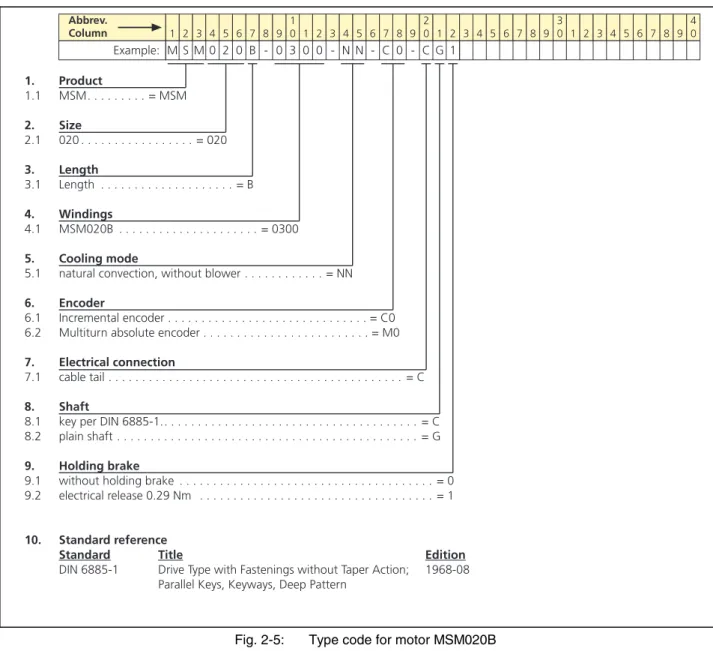
Motor MSM020B
1 2 3 4 5 6 7 8 9 10 1 2 3 4 5 6 7 8 9 20 1 2 3 4 5 6 7 8 9 30 1 2 3 4 5 6 7 8 9 40 Example: Abbrev. Column M S M 0 2 0 B - 0 3 0 0 - N N - C 0 - C G 1 1. Product 1.1 MSM. . . = MSM 2. Size 2.1 020 . . . = 020 3. Length 3.1 Length . . . = B 4. Windings 4.1 MSM020B . . . = 0300 5. Cooling mode5.1 natural convection, without blower . . . = NN
6. Encoder
6.1 Incremental encoder . . . = C0 6.2 Multiturn absolute encoder . . . = M0
7. Electrical connection
7.1 cable tail . . . = C
8. Shaft
8.1 key per DIN 6885-1.. . . = C 8.2 plain shaft . . . = G
9. Holding brake
9.1 without holding brake . . . = 0 9.2 electrical release 0.29 Nm . . . = 1
10. Standard reference
Standard Title Edition
DIN 6885-1 Drive Type with Fastenings without Taper Action; 1968-08 Parallel Keys, Keyways, Deep Pattern
Fig. 2-5: Type code for motor MSM020B
of CMA/Flodyne/Hydradyne ▪ Motion Control ▪ Hydraulic ▪ Pneumatic ▪ Electrical ▪ Mechanical ▪ (800) 426-5480 ▪ www.cmafh.com
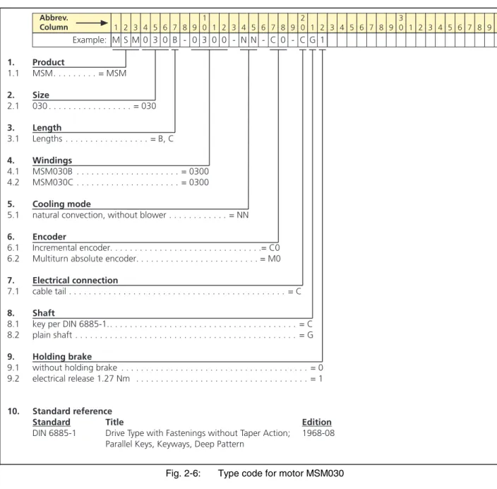
Motor MSM030
1 2 3 4 5 6 7 8 9 10 1 2 3 4 5 6 7 8 9 20 1 2 3 4 5 6 7 8 9 30 1 2 3 4 5 6 7 8 9 40 Example: Abbrev. Column M S M 0 3 0 B - 0 3 0 0 - N N - C 0 - C G 1 1. Product 1.1 MSM. . . = MSM 2. Size 2.1 030 . . . = 030 3. Length 3.1 Lengths . . . = B, C 4. Windings 4.1 MSM030B . . . = 0300 4.2 MSM030C . . . = 0300 5. Cooling mode5.1 natural convection, without blower . . . = NN
6. Encoder
6.1 Incremental encoder. . . .= C0 6.2 Multiturn absolute encoder. . . = M0
7. Electrical connection
7.1 cable tail . . . = C
8. Shaft
8.1 key per DIN 6885-1.. . . = C 8.2 plain shaft . . . = G
9. Holding brake
9.1 without holding brake . . . = 0 9.2 electrical release 1.27 Nm . . . = 1
10. Standard reference
Standard Title Edition
DIN 6885-1 Drive Type with Fastenings without Taper Action; 1968-08 Parallel Keys, Keyways, Deep Pattern
Fig. 2-6: Type code for motor MSM030
Courtesy of CMA/Flodyne/Hydradyne ▪ Motion Control ▪ Hydraulic ▪ Pneumatic ▪ Electrical ▪ Mechanical ▪ (800) 426-5480 ▪ www.cmafh.com
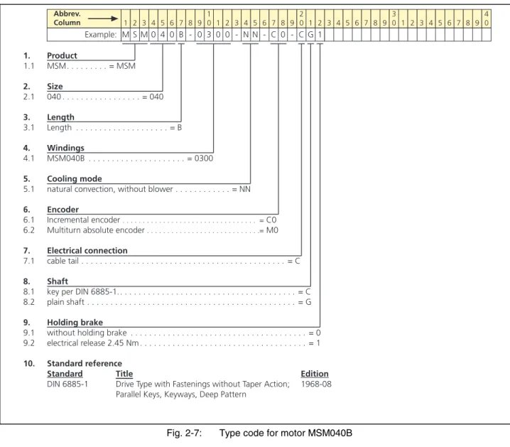
Motor MSM040B
1 2 3 4 5 6 7 8 9 10 1 2 3 4 5 6 7 8 9 20 1 2 3 4 5 6 7 8 9 30 1 2 3 4 5 6 7 8 9 40 Example: Abbrev. Column M S M 0 4 0 B - 0 3 0 0 - N N - C 0 - C G 1 1. Product 1.1 MSM. . . = MSM 2. Size 2.1 040 . . . = 040 3. Length 3.1 Length . . . = B 4. Windings 4.1 MSM040B . . . = 0300 5. Cooling mode5.1 natural convection, without blower . . . = NN
6. Encoder
6.1 Incremental encoder . . . = C0 6.2 Multiturn absolute encoder . . . .= M0 7. Electrical connection
7.1 cable tail . . . = C
8. Shaft
8.1 key per DIN 6885-1.. . . = C 8.2 plain shaft . . . = G
9. Holding brake
9.1 without holding brake . . . = 0 9.2 electrical release 2.45 Nm . . . = 1 10. Standard reference
Standard Title Edition
DIN 6885-1 Drive Type with Fastenings without Taper Action; 1968-08 Parallel Keys, Keyways, Deep Pattern
Fig. 2-7: Type code for motor MSM040B
of CMA/Flodyne/Hydradyne ▪ Motion Control ▪ Hydraulic ▪ Pneumatic ▪ Electrical ▪ Mechanical ▪ (800) 426-5480 ▪ www.cmafh.com
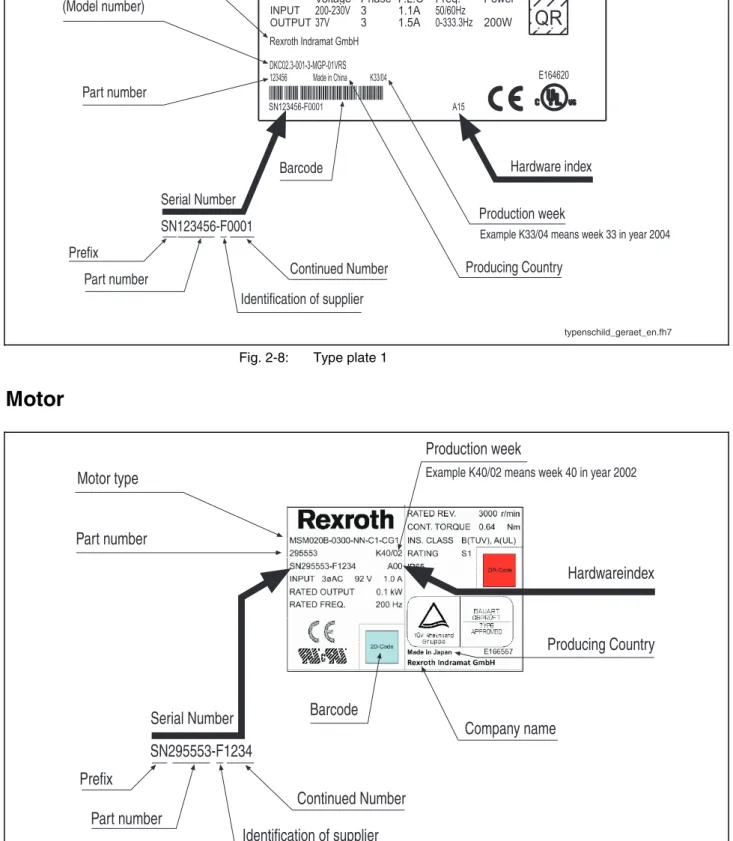
2.2 Type
Plates
Drive Controller
typenschild_geraet_en.fh7 R Continued Number Identification of supplier Company nameExample K33/04 means week 33 in year 2004
Production week Serial Number
SN123456-F0001
Barcode Hardware index
Device type (Model number) Part number Part number A15 SN123456-F0001 K33/04
Voltage Phase F.L.C Freq. Power
INPUT
OUTPUT200-230V37V 33 1.1A1.5A 50/60Hz0-333.3Hz 200W
123456 Rexroth Indramat GmbH DKC02.3-001-3-MGP-01VRS E164620
QR
Producing Country Made in China PrefixFig. 2-8: Type plate 1
Motor
typenschild_motor_text_en.fh7
Company name
Example K40/02 means week 40 in year 2002
Production week
Part number
Producing Country
Motor type
Barcode
Hardwareindex
A15SN295553-F1234
Continued Number
Identification of supplier
Serial Number
Part number
Prefix
Fig. 2-9: Motor type plate
Courtesy of CMA/Flodyne/Hydradyne ▪ Motion Control ▪ Hydraulic ▪ Pneumatic ▪ Electrical ▪ Mechanical ▪ (800) 426-5480 ▪ www.cmafh.com
2.3
Drive Controller – Motor Combinations
Note: The individual drive controllers may only be operated with the respective motors.
Drive controller Motor Properties (motor)
DKCxx.x-004 MSM020B-0300-NN-C0-CG0 MSM020B-0300-NN-C0-CG1 MSM020B-0300-NN-C0-CC0 MSM020B-0300-NN-C0-CC1 MSM020B-0300-NN-M0-CG0 MSM020B-0300-NN-M0-CG1 MSM020B-0300-NN-M0-CC0 MSM020B-0300-NN-M0-CC1
100 W: incremental, plain shaft, without brake
100 W: incremental, plain shaft, with brake
100 W: incremental, key, without brake
100 W: incremental, key, with brake
100 W: absolute, plain shaft, without brake
100 W: absolute, plain shaft, with brake
100 W: absolute, key, without brake
100 W: absolute, key, with brake
DKCxx.x-008 MSM030B-0300-NN-C0-CG0 MSM030B-0300-NN-C0-CG1 MSM030B-0300-NN-C0-CC0 MSM030B-0300-NN-C0-CC1 MSM030B-0300-NN-M0-CG0 MSM030B-0300-NN-M0-CG1 MSM030B-0300-NN-M0-CC0 MSM030B-0300-NN-M0-CC1
200 W: incremental, plain shaft, without brake
200 W: incremental, plain shaft, with brake
200 W: incremental, key, without brake
200 W: incremental, key, with brake
200 W: absolute, plain shaft, without brake
200 W: absolute, plain shaft, with brake
200 W: absolute, key, without brake
200 W: absolute, key, with brake
DKCxx.x-012 MSM030C-0300-NN-C0-CG0 MSM030C-0300-NN-C0-CG1 MSM030C-0300-NN-C0-CC0 MSM030C-0300-NN-C0-CC1 MSM030C-0300-NN-M0-CG0 MSM030C-0300-NN-M0-CG1 MSM030C-0300-NN-M0-CC0 MSM030C-0300-NN-M0-CC1
400 W: incremental, plain shaft, without brake
400 W: incremental, plain shaft, with brake
400 W: incremental, key, without brake
400 W: incremental, key, with brake
400 W: absolute, plain shaft, without brake
400 W: absolute, plain shaft, with brake
400 W: absolute, key, without brake
400 W: absolute, key, with brake
DKCxx.x-018 MSM040B-0300-NN-C0-CG0 MSM040B-0300-NN-C0-CG1 MSM040B-0300-NN-C0-CC0 MSM040B-0300-NN-C0-CC1 MSM040B-0300-NN-M0-CG0 MSM040B-0300-NN-M0-CG1 MSM040B-0300-NN-M0-CC0 MSM040B-0300-NN-M0-CC1
750 W: incremental, plain shaft, without brake
750 W: incremental, plain shaft, with brake
750 W: incremental, key, without brake
750 W: incremental, key, with brake
750 W: absolute, plain shaft, without brake
750 W: absolute, plain shaft, with brake
750 W: absolute, key, without brake
750 W: absolute, key, with brake
Fig. 2-10: Drive controller – motor combinations
2.4
Scope of Supply
Connection accessories for connections X1, X2 and X3 (SUP-E02-DKC*CS-CONPWR) of CMA/Flodyne/Hydradyne ▪ Motion Control ▪ Hydraulic ▪ Pneumatic ▪ Electrical ▪ Mechanical ▪ (800) 426-5480 ▪ www.cmafh.com
3
Ratings and Dimensions
Description Symbol Unit DKC**.3-004 DKC**.3-008 DKC**.3-012 DKC**.3-018
listing according UL-standard (UL)
UL 508 C listing according CSA-standard
(UL)
Canadian National Standard(s) C22.2 No. 14-05
UL files (UL) E 227957
pollution degree (UL) Use in a pollution degree 2 environment. The device is to be installed in an enclosure that provides pollution degree 2. maximum ambient temperature
with nominal data (UL) Tamax °C
40 °C maximum ambient temperature
with reduced nominal data (UL) Tamax_red °C
55 °C
Weight m kg 1,8 2,1
Device height (UL) 1) H mm 182
Device depth (UL) 2) T mm 170
Device width (UL) 3) B mm 55 70
minimum distance on the top of
the device 4) dtop mm
50 minimum distance on the
bottom of the device 5) dbot mm
50 rated control voltage input (UL)
6) UN3 V 24 ac
rated power consumption control voltage input without holding brake, without control section at UN3 = DC 24 V (UL) 7)
PN3 W
n / a n / a n / a n / a
short circuit current rating, SCCR, symmetrical amperes (UL) 8)
ISCCR A
rms
5000
rated input voltage, power (UL)
9) V 200 – 230 ac 200 – 240 ac
tolerance rated input voltage
(UL) %
n / a n / a n / a n / a
input number of phases (UL) 3 (1) 3 (1) 3(1) 3
input frequency (UL) fLN Hz 50 / 60 Hz
tolerance input frequency (UL) Hz n / a n / a n / a n / a
maximum input current (UL) 10) IL_cont A 1,1 1,3 2,2 3,1
branch circuit protection fuse (UL) 11)
2 2 3 4
field wiring material (UL) 12) Use 60/75 °C copper wire only, use class 1 wire only or equivalent required wire size according UL
508 A (internal wiring); at IL_cont
(UL) 13)
ALN
AWG 14
maximum output voltage (UL) Uout V 84 92 106 116
output number of phases (UL) 3
maximum output current (UL) Iout_max A 1 1,6 2,5 4,3
maximum output frequency
(UL) 14) fout Hz 333,3 300 Courtesy of CMA/Flodyne/Hydradyne ▪ Motion Control ▪ Hydraulic ▪ Pneumatic ▪ Electrical ▪ Mechanical ▪ (800) 426-5480 ▪ www.cmafh.com
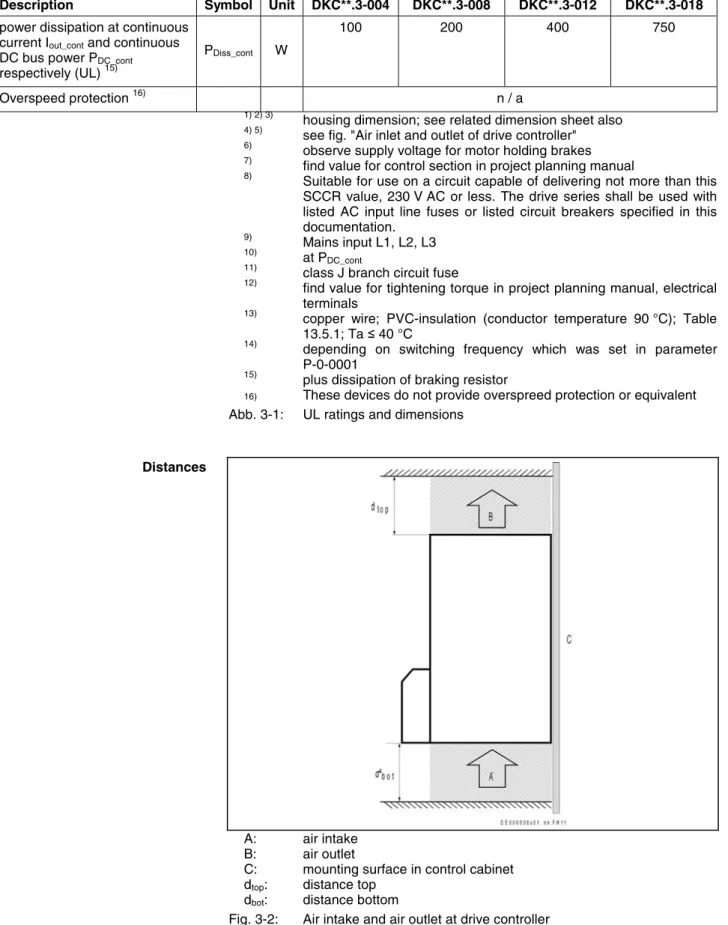
Description Symbol Unit DKC**.3-004 DKC**.3-008 DKC**.3-012 DKC**.3-018
power dissipation at continuous current Iout_cont and continuous
DC bus power PDC_cont
respectively (UL) 15)
PDiss_cont W
100 200 400 750
Overspeed protection 16) n / a
1) 2) 3)
housing dimension; see related dimension sheet also
4) 5)
see fig. "Air inlet and outlet of drive controller"
6)
observe supply voltage for motor holding brakes
7)
find value for control section in project planning manual
8)
Suitable for use on a circuit capable of delivering not more than this SCCR value, 230 V AC or less. The drive series shall be used with listed AC input line fuses or listed circuit breakers specified in this documentation. 9) Mains input L1, L2, L3 10) at PDC_cont 11)
class J branch circuit fuse
12)
find value for tightening torque in project planning manual, electrical terminals
13)
copper wire; PVC-insulation (conductor temperature 90 °C); Table 13.5.1; Ta ≤ 40 °C
14)
depending on switching frequency which was set in parameter P-0-0001
15)
plus dissipation of braking resistor
16) These devices do not provide overspreed protection or equivalent
Abb. 3-1: UL ratings and dimensions
A: air intake B: air outlet
C: mounting surface in control cabinet dtop: distance top
dbot: distance bottom
Fig. 3-2: Air intake and air outlet at drive controller
Distances of CMA/Flodyne/Hydradyne ▪ Motion Control ▪ Hydraulic ▪ Pneumatic ▪ Electrical ▪ Mechanical ▪ (800) 426-5480 ▪ www.cmafh.com
4 Reference
Documentations
4.1 Overview
Title Type Document Typecode
Functional Description DOK-ECODR3-MGP-01VRS**-FKxx-EN-P Parameter Description DOK-ECODR3-MGP-01VRS**-PAxx-EN-P Rexroth EcoDrive Cs
Drive Controllers MGP 01VRS
Troubleshooting Guide DOK-ECODR3-MGP-01VRS**-WA01-EN-P 1) In the document typecodes, "xx" is a wild card for the current edition
of the documentation (example: "PR01" is the first edition of a Project Planning Manual)
Fig. 4-1: Documentations - Overview
5
Instructions for Use
5.1 Overcurrent
Protection
Branch circuit protection has to be provided externally according to the maximum values (voltage and current or voltage and percent of FLA of the fuses [FLA: Full Load Ampacity]).
Courtesy of CMA/Flodyne/Hydradyne ▪ Motion Control ▪ Hydraulic ▪ Pneumatic ▪ Electrical ▪ Mechanical ▪ (800) 426-5480 ▪ www.cmafh.com
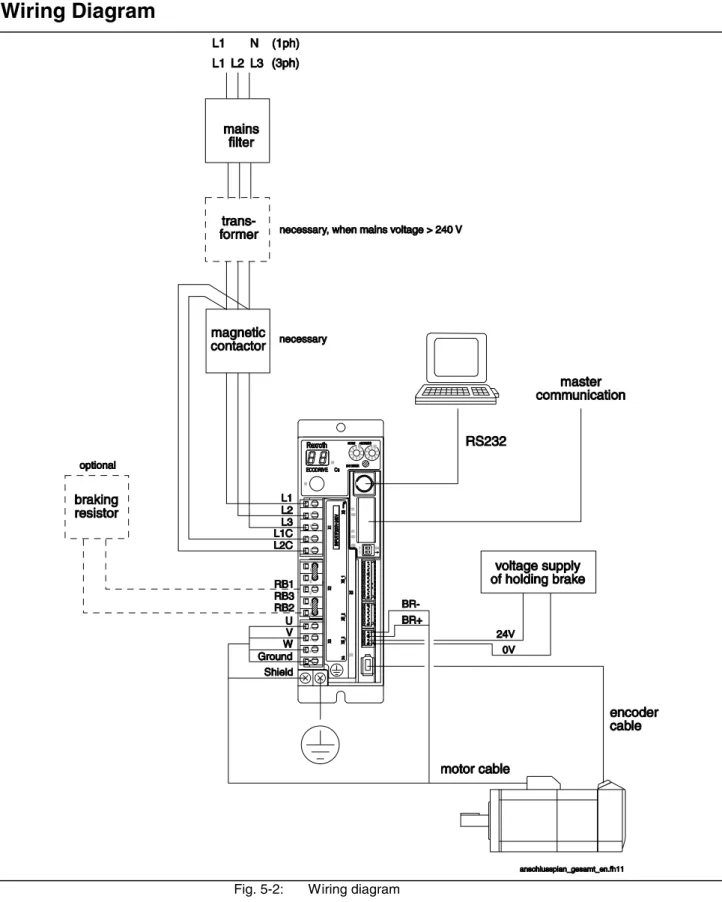
5.2 Connections
Wiring Diagram
Fig. 5-2: Wiring diagram
of CMA/Flodyne/Hydradyne ▪ Motion Control ▪ Hydraulic ▪ Pneumatic ▪ Electrical ▪ Mechanical ▪ (800) 426-5480 ▪ www.cmafh.com
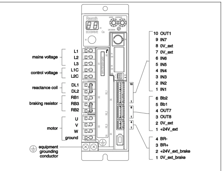
Connection Diagram
Fig. 5-3: Total connection diagram
X1, Mains and Control Voltage
DANGER
Lethal electric shock caused by live parts with
more than 50 V!
⇒ Before starting to work on the drive controller switch off the voltage supply via the main switch or the circuit breaker.
⇒ Always mount or dismount both connectors (motor connection and mains connection) at the drive controller.
⇒ Observe the notes in the "Important Notes" chapter. Courtesy of CMA/Flodyne/Hydradyne ▪ Motion Control ▪ Hydraulic ▪ Pneumatic ▪ Electrical ▪ Mechanical ▪ (800) 426-5480 ▪ www.cmafh.com
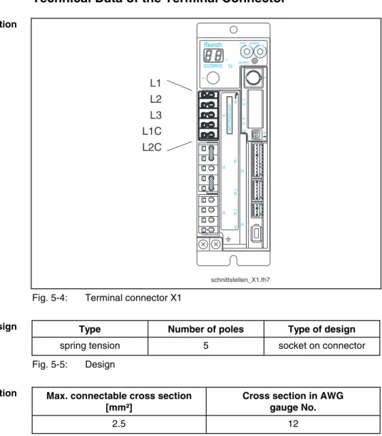
Technical Data of the Terminal Connector
schnittstellen_X1.fh7 TX RX S20 2 1 ON X4 X5 X6 W V U RB2 RB3 RB1 DL2 DL1 9 8 7 6 5 432 1 9 8 7 6 5 423 1ADDRESS NODE 0 0 Rexroth ECODRIVE Cs S1 H1 S2 S3 LINE ERROR X20 X21 X4 X5_3 X5_2 X5_1 INPUTíF200V -240V X3 X2 X1 X6 L2C L1C L3 L2 L1 L1 L2 L3 L1C L2CFig. 5-4: Terminal connector X1
Type Number of poles Type of design
spring tension 5 socket on connector
Fig. 5-5: Design
Max. connectable cross section [mm²]
Cross section in AWG gauge No.
2.5 12
Fig. 5-6: Connection cross section
X2, Additional Choke and Braking Resistor
Technical Data of the Terminal Connector
TX RX S20 2 1 ON X4 X5 X6 9 8 7 6 5 4132 9 8 7 6 5 4132 ADDRESS NODE 0 0 Rexroth ECODRIVE Cs S1 H1 S2 S3 LINE ERROR X20 X21 X4 X5_3 X5_2 X5_1 INPUTíF200V -240V X3 X2 X1 X6 DL1 DL2 RB1 RB3 RB2 Graphic Representation Design
Connection Cross Section
Graphic Representation of CMA/Flodyne/Hydradyne ▪ Motion Control ▪ Hydraulic ▪ Pneumatic ▪ Electrical ▪ Mechanical ▪ (800) 426-5480 ▪ www.cmafh.com
Type Number of poles Type of design
spring tension 5 socket on connector
Fig. 5-8: Design Cross section single-core [mm²] Cross section in AWG gauge No. 0,75 - 2 18 - 14
Fig. 5-9: Connection cross section
DL1, DL2: Additional Choke
By connecting an additional choke it is possible to increase the allowed continuous DC bus power.
Note: If there isn't any choke used these connections must be jumpered. A wire bridge is supplied together with the device.
Note: Rexroth doesn't deliver additional chokes for Rexroth EcoDrive Cs drives. device-external X2_Dx.FH7 X2 DL1 DL2 DL1 DL2 device-internal
Fig. 5-10: Connection for choke
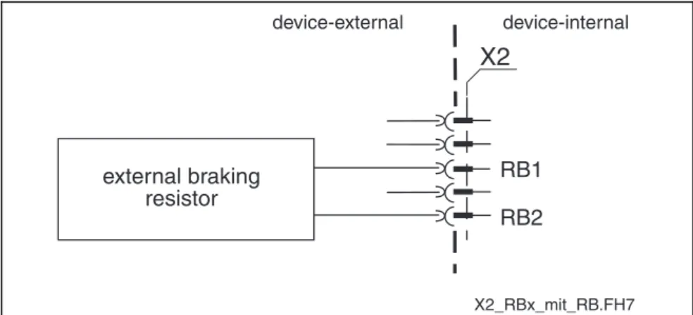
RB1, RB2, RB3: Braking Resistor
Note: The internal braking resistor causes a derating of the continuous DC bus power.
By connecting an external braking resistor the derating of the continuous DC bus power can be prevented.
Note: When an external braking resistor is used, the drive has to be informed of this fact by means of the DriveTop commissioning software (call in DriveTop by menu item "Drive Functions -> Drive controller")
An external braking resistor is available as an accessory.
Design
Connection Cross Section
Choke Connection Accessory Courtesy of CMA/Flodyne/Hydradyne ▪ Motion Control ▪ Hydraulic ▪ Pneumatic ▪ Electrical ▪ Mechanical ▪ (800) 426-5480 ▪ www.cmafh.com
device-external device-internal X2_RBx_mit_RB.FH7
X2
RB1 RB2 external braking resistorFig. 5-11: Connection for braking resistor
Note: If you do not use any external braking resistor, the RB2 and RB3 connections must be jumpered.
X2_RBx_ohne_RB.FH7
X2
RB2
RB3
device-external device-internal
Fig. 5-12: Jumper on RB2 and RB3
X3, Motor
DANGER
Lethal electric shock caused by live parts with
more than 50 V!
⇒ Before starting to work on the drive controller switch off the voltage supply via the main switch or the fuse.
⇒ Always mount or dismount both connectors (motor connection and mains connection) at the drive controller.
⇒ Observe the notes in the "Important Notes" chapter.
Braking Resistor Connection
of CMA/Flodyne/Hydradyne ▪ Motion Control ▪ Hydraulic ▪ Pneumatic ▪ Electrical ▪ Mechanical ▪ (800) 426-5480 ▪ www.cmafh.com
Technical Data of the Terminal Connector
schnittstellen_X3.fh7 TX RX S20 2 1 ON X4 X5 X6 9 8 7 6 5 423 1 9 8 7 6 5 432 1 ADDRESS NODE 0 0 Rexroth ECODRIVE Cs S1 H1 S2 S3 LINE ERROR X20 X21 X4 X5_3 X5_2 X5_1 INPUTíF200V -240V X3 X2 X1 X6 U V W GroundFig. 5-13: Terminal connector X3
Type Number of poles Type of design
spring tension 4 socket on connector
Fig. 5-14: Design
Max. connectable cross section [mm²]
Max. cross section in AWG gauge No.:
0,75 - 2 18 - 14
Fig. 5-15: Connection cross section
For connecting drive controller and motor please use the appropriate Rexroth motor power cables.
Cable length:
The maximum cable length is 40 m with: • ready-made Rexroth cable
• ambient temperature of ≤ 40 °C according to EN 60204 • maximum switching frequency of 8 kHz
WARNING
No warranty!
If cables manufactured by a company other than Bosch Rexroth resp. cables longer than 40 m are used, the Bosch Rexroth warranty for the entire drive system becomes invalid.
Use ready-made Rexroth cables!
Graphic Representation
Design
Connection Cross Section
Motor Cables Courtesy of CMA/Flodyne/Hydradyne ▪ Motion Control ▪ Hydraulic ▪ Pneumatic ▪ Electrical ▪ Mechanical ▪ (800) 426-5480 ▪ www.cmafh.com
Equipment Grounding Conductor Connection
DANGER
Lethal electric shock caused by live parts with
more than 50 V!
Connect the equipment grounding conductor connection of the drive controller to the equipment grounding system of the control cabinet.
Check the continuity of the equipment grounding conductors from the mains connection to the connected motors.
Technical Data of the Terminal Connector
Fig. 5-16: Equipment grounding conductor connection
Type Number Type of design
terminal block 2 threaded terminal end for M4 ring cable lugs Fig. 5-17: Design
Cross section single-core
[mm²]
Max. cross section in AWG gauge No.
2.0 14
Fig. 5-18: Connection cross section
Contrary to the safety instruction in chapter 1.1 a copper conductor cross section of 2 mm2 would be sufficient.
Maximum 1 m
Connection of Control Interfaces and Terminals
Graphic RepresentationDesign
Connection Cross Section
Cable Length of CMA/Flodyne/Hydradyne ▪ Motion Control ▪ Hydraulic ▪ Pneumatic ▪ Electrical ▪ Mechanical ▪ (800) 426-5480 ▪ www.cmafh.com
X5_3: Holding Brake
DANGER
Dangerous movements! Danger to personnel
from falling or dropping axes!
⇒ The optionally delivered motor holding brake or an external brake controlled by the drive controller are not sufficient to guarantee the safety of personnel!
⇒ Personnel safety must be achieved using higher-ranking, fail-safe procedures:
Dangerous areas should be blocked off with fences or grids.
Additionally secure vertical axes against falling or sinking after switching off the motor power by, for example:
- mechanically blocking the vertical axis, - adding an external braking/catching/clamping mechanism or
- providing sufficient counterbalance for the axis.
Switching performance: see Functional Description of firmware.
Technical Data of the Terminal Connector
schnittstellen_X53.fh7 TX RX S202 1 ON X4 X5 X6 9 8 7 6 5 4123 9 8 7 6 5 4123 ADDRESS NODE 0 0 Rexroth ECODRIVE Cs S1 H1 S2 S3 LINE ERROR X20 X21 X4 X5_3 X5_2 X5_1 INPUTíF200V -240V X3 X2 X1 X6 BR-BR+ +24V_ext_brake 0V_ext_brake
Fig. 5-19: Terminal connector X5_3
Type Number of poles Type of design
spring tension 4 socket on connector
Fig. 5-20: Design
Max. cross section single-core
[mm²]
Cross section in AWG gauge No.
0,25 - 0.5 23 - 20
Fig. 5-21: Connection cross section
Graphic Representation
Design
Connection Cross Section
Courtesy of CMA/Flodyne/Hydradyne ▪ Motion Control ▪ Hydraulic ▪ Pneumatic ▪ Electrical ▪ Mechanical ▪ (800) 426-5480 ▪ www.cmafh.com
4 holding brake-3 holding brake+ 2 +24V_ext_brake 1 0V_ext_brake
Fig. 5-22: Holding brake and voltage connection
Load Capacity of the BR+, BR- connection:
max. switching voltage DC 36 V
max. switching current DC 1 A
max. continuous current DC 1 A voltage drop electronic contact 100 mV
guaranteed number of switching operations unlimited (wear-resistant electronic contact) short-circuit and overload protection present
Voltage connection for brake
Note: The motor holding brake is not supplied by the drive controller. Observe the data of the motor holding brake.
Note: It is impossible to loop through the voltages to other drive controllers. Other drive controllers have to be connected to the voltage source in star-shaped form.
CAUTION
Risk of damage!
⇒ The maximum allowed current load of the terminal connectors for the voltage supply of the brake and the control voltage supply must also be observed in the case of a short circuit.
max. voltage at X5_3.1 referring to X5_3.2: 36 V current consumption at X5_3.3 and required supply
voltage:
see Project Planning Manual
line cross section min. 1 mm2
voltage stability of a single strand against
ground: ≥ 750 V
line routing: parallel where possible (twist) max. inductance between 24 V source
and X5_3:
100 µH
(corresponds to approx. 2 x 75 m)
The drive controller assumes the control of the holding brake.
BR+, BR-Connection
Line for Voltage Connection of Brake
Controlling the Motor Holding Brake of CMA/Flodyne/Hydradyne ▪ Motion Control ▪ Hydraulic ▪ Pneumatic ▪ Electrical ▪ Mechanical ▪ (800) 426-5480 ▪ www.cmafh.com
Connecting the Motor
After having mounted the motor mechanically as specified, proceed to connecting the motor.
DANGER
Danger to life by electric voltage! Handling
within the range of live parts is extremely
dangerous. Therefore:
⇒ Any work required on the electric system may only be carried out by skilled electricians. It is absolutely necessary to use electric tools.
⇒ Before starting work, the system must be de-energized and the power switch be secured against unintentional or unauthorized re-energization.
⇒ Before starting work, the appropriate measuring equipment must be used to check whether parts of the system are still applied to residual voltage (e.g. caused by capacitors, etc.). If yes, wait until these parts have discharged.
WARNING
Injuries to persons or property are possible!
Interrupting or connecting live lines may cause
unpredictable dangerous situations or lead to
physical damage. Therefore:
⇒ Connect and disconnect plug connectors only when they are dry and de-energized.
⇒ During operation of the system, all plug connectors must be securely tightened.
WARNING
Risk of short-circuit caused by liquid coolant or
lubricant! Short-circuits of live lines may cause
unpredictable dangerous situations or lead to
physical damage. Therefore:
⇒ Provide open mating sides of power plug connectors with safety caps when installing or replacing drive components, if you cannot exclude that they might be moistened with liquid coolant or lubricant.
The connection diagrams by Rexroth are exclusively intended for the preparation of system circuit diagrams!
⇒ Connect the motor as specified in the machine manufacturer’s system circuit diagram!
5.3
Startup, Operation, and Maintenance
Startup
The MSM motors may be put into operation only if they have been carefully and properly mounted and if the electric connection has been properly established. Courtesy of CMA/Flodyne/Hydradyne ▪ Motion Control ▪ Hydraulic ▪ Pneumatic ▪ Electrical ▪ Mechanical ▪ (800) 426-5480 ▪ www.cmafh.com
Before putting the MSM motors into operation, the following must be checked and/or ensured:
• It must be possible to turn the rotor manually with the holding brake opened; there may be no running noise (e.g. rubbing). If necessary, the holding brake must be opened by applying a DC voltage of 24 V ±10%.
• The motor must be mounted and aligned correctly. The motor flange must be coupled to the machine structure or the gear absolutely even. • It must be ensured that all electric connections (motor and drive
controller) have been established as specified and that the cable screw unions have been tightened.
• It must be ensured that the protective conductor and/or the protective grounding have been executed properly.
• If the optional holding brake is used, its operational reliability must be ensured.
• Shock protection measures against live and moving parts must be provided for.
MSM motors may be put into operation only with Rexroth EcoDrive Cs drive controllers by Rexroth. After the connection has been properly established and the above requirements are complied with, the MSM motor can be put into operation via the drive controller.
Note: Startup of the drives is described in the Functional Description of the particular firmware MGPxxVRS. Request the corresponding product documentation from your local sales office.
Operation
Ensure that the ambient conditions are kept during operation.
Maintenance
Cleaning
Excessive dirt, dust or shavings may affect the function of the motors adversely, may in extreme cases even cause a failure of the motors. For that reason, you should clean
• the cooling ribs of the motors at regular intervals, in order to obtain a sufficiently large heat radiation surface. If the cooling ribs are dirty in part, sufficient heat dissipation via the environmental air is not possible any longer.
An insufficient heat radiation may have undesired consequences. The bearing service life is reduced by operation at impermissibly high temperatures (the bearing grease is decomposing). Switchoff caused by overtemperature despite operation on the basis of selected data, because the appropriate cooling is missing.
Bearings
The nominal service life of the bearings is 30.000 h, if the permissible radial and axial forces are not exceeded. Even if the bearings are loaded with higher forces to a minor degree only, their service life is affected negatively.
Connection Cable
Before startup Startup Cooling ribs of CMA/Flodyne/Hydradyne ▪ Motion Control ▪ Hydraulic ▪ Pneumatic ▪ Electrical ▪ Mechanical ▪ (800) 426-5480 ▪ www.cmafh.comCheck any optionally present energy management chains (drag chains) for defects.
DANGER
Electrocution by live parts of more than 50 V!
⇒ Do not repair any connection lines provisionally. If the slightest defects are detected in the cable sheath, the system must be put out of operation immediately. Then the cable must be replaced.
Check the protective conductor connection for proper state and tight seat at regular intervals and replace it, if necessary.
Holding brake
The check can be done by means of a function (brake check) integrated in the firmware (see Functional Description).
Battery
Motors with absolute encoders need a battery to back-up the encoder signals. The battery is set into the drive controller (Exception: Rexroth Cartesian Motion Systems (CMS)).
The drive controller observes voltage of battery and gives just in time a warning “F248 Low battery voltage".
The service life of the battery depends on the ratio of switch-ON-duration to switch-OFF-duration: OFF ON t t I=
tON: duration, the drive controller is switched on
tOFF: duration, the drive controller is switched off
I: ON/OFF ratio Fig. 5-23: ON/OFF ratio
Service life of battery (Q = 1800 mAh)
0 2 4 6 8 10 12 14 16 18 20 0 1 2 3 4 5 6 7 8 9 10 I (ON/OFF ratio) Serv ic e life in y e ars Standby-operation
Fig. 5-24: Service life of battery
Thus, the longer the drive controller is switched on, the longer is the service life of the battery.
Absolute encoders Warning message Service life Courtesy of CMA/Flodyne/Hydradyne ▪ Motion Control ▪ Hydraulic ▪ Pneumatic ▪ Electrical ▪ Mechanical ▪ (800) 426-5480 ▪ www.cmafh.com
Prior to using the battery you always have to refresh the battery: 1. Connect connector of battery to mating connector of resistor (see
figure below)
(Battery and resistor are parts of SUP-E03-DKC*CS-BATTRY)
batterie_refresh.fh7 resistor
mating connector
connector
battery
Fig. 5-25: Battery refreshing 2. Wait 2 minutes 3. Disconnect battery
Depending on the operating hours of the motor, the time available for changing the battery is limited:
batterie_pufferzeit.FH7 capacitor v oltage [V] 3,0 554 792 79 2,0 4,0 5,0
A
B
C
D
time [s]A: operating hours: 3000 => backup time 79 s B: operating hours: 1000 => backup time 554 s
C: operating hours: 0 (condition as supplied) => backup time 792 s D: range of battery undervoltage (2.3 to 2.7 V)
Fig. 5-26: Backup time of supply voltage
During this time the supply voltage of the absolute value encoder is backed up so that the information regarding the absolute value encoder position is maintained.
Refresh
Changing the battery
of CMA/Flodyne/Hydradyne ▪ Motion Control ▪ Hydraulic ▪ Pneumatic ▪ Electrical ▪ Mechanical ▪ (800) 426-5480 ▪ www.cmafh.com
Note: If you exceed the backup time when changing the battery the absolute value encoder position gets lost.
Note: If you use the drive controllers together with Rexroth Cartesian Motion Systems (CMS), regard the instructions of the CMS manual (RE 82 674) now.
1. Push battery cover downwards and remove cover:
batteriefach.fh7 X21 X20 TX RX S20 2 1 ON X1 X2 X3
2. Remove old battery
3. If not already done so, refresh new battery now (see instructions above)
4. Insert new battery
Courtesy of CMA/Flodyne/Hydradyne ▪ Motion Control ▪ Hydraulic ▪ Pneumatic ▪ Electrical ▪ Mechanical ▪ (800) 426-5480 ▪ www.cmafh.com
5. Connect connector attached to the battery to one of the two mating connectors on the drive controller
batteriefach_front.fh7 W V U RB2 RB3 RB1 DL2 DL1 L2C L1C L3 L2 L1 mating connector connector battery
6. Attach battery cover. Push cover upwards until it snaps in
7. Dispose old battery according to the valid directions of your country
5.4 Installation
General Information on How to Install the Drive Controller
Damage can be caused to the drive controller or circuit boards if electrostatic charging present in people and/or tools is discharged across them. Therefore, please note the following information:
CAUTION
Electrostatic charges can cause damage to
electronic components and interfere with their
operational safety!
⇒ Exposed conductive parts coming into contact with components and circuit boards must be discharged by means of grounding. Otherwise errors may occur when triggering motors and moving elements. Such exposed conductive parts include:
• the copper bit when soldering
• the human body (ground connection caused by touching a conductive, grounded item)
• parts and tools (place them on a conductive support)
Endangered components may only be stored or dispatched in conductive packaging. of CMA/Flodyne/Hydradyne ▪ Motion Control ▪ Hydraulic ▪ Pneumatic ▪ Electrical ▪ Mechanical ▪ (800) 426-5480 ▪ www.cmafh.com
Note: Rexroth connection diagrams are only to be used for producing installation connection diagrams. The machine manufacturer’s installation connection diagrams must be used for wiring the installation!
• Lay signal lines separately from the load resistance lines because of the occurrence of interference.
• Transmit analog signals (e.g. command values, actual values) via shielded lines.
• Do not connect mains, DC bus or power leads to low voltages or allow them to come into contact with these.
• When carrying out a high voltage test or an applied-overvoltage withstand test on the machine’s electrical equipment, disconnect all connections to the devices. This protects the electronic components (allowed in accordance with EN 60204-1). During their routine testing, Rexroth drive components are tested for high voltage and insulation in accordance with EN 50178.
CAUTION
Risk of damage to the drive controller by
connecting and disconnecting live connections!
⇒ Do not connect and disconnect live connections.
Courtesy of CMA/Flodyne/Hydradyne ▪ Motion Control ▪ Hydraulic ▪ Pneumatic ▪ Electrical ▪ Mechanical ▪ (800) 426-5480 ▪ www.cmafh.com
Sizing of Enclosure and Control Cabinet
Control Cabinet with Multiple-Line Structure
Note: Particular attention should be paid to the maximum allowed air intake temperature of components when they are arranged in multiple lines in the control cabinet. Where necessary, cooling air guides are to be provided with blowers specially used for this purpose.
air guide
addit-ional blower
conveying direction of heated air in flow-off area
conveying direction of heated air in flow-off area intake area of cooling air for
upper device line
intake area of cooling air for lower device line
outlet air to cooling unit
supply air from cooling unit
Fig. 5-27: Example of arrangement for multiple-line structure with components
Arrangement of Cooling Units
CAUTION
Possible damage to the drive controller Operational safety of the machine endangered! Note the following instructions!
Due to the operating principle, condensation water is formed when cooling units are used. For this reason, please observe the following information: • Always position cooling units in such a way that condensation water
cannot drip onto electronic equipment in the control cabinet.
• Position the cooling unit in such a way that the blower of the cooling unit does not spray accumulated condensation water onto electronic equipment.
Avoiding Dripping or Sprayed Water of CMA/Flodyne/Hydradyne ▪ Motion Control ▪ Hydraulic ▪ Pneumatic ▪ Electrical ▪ Mechanical ▪ (800) 426-5480 ▪ www.cmafh.com
electronic equipment Eb0001f1.fh7
incorrect
correct
warm cold Cooling system Cabinet warm cold Air duct electronic equipment Cabinet Cooling systemFig. 5-28: Arranging the cooling unit on the control cabinet
electronic equip. Eb0002f1.fh7
incorrect
cooling unit control cabinet air inflow air outflowcorrect
control cabinet air inflow air duct electronic equip. cooling unitFig. 5-29: Arranging the cooling unit at the front of the control cabinet
Moisture condensation occurs when the temperature of the device is lower than the ambient temperature.
• Set cooling units with temperature adjustment to the maximum surrounding temperature and not lower!
• Set cooling units with follow-up temperature in such a way that the interior temperature of the control cabinet is no lower than the temperature of the surrounding air. Set the temperature limitation to the maximum surrounding temperature!
Avoiding Moisture Condensation
Courtesy of CMA/Flodyne/Hydradyne ▪ Motion Control ▪ Hydraulic ▪ Pneumatic ▪ Electrical ▪ Mechanical ▪ (800) 426-5480 ▪ www.cmafh.com
• Only use well-sealed control cabinets so that moisture condensation cannot arise as a result of warm and moist external air entering the cabinet.
In the event that control cabinets are operated with the doors open (commissioning, servicing etc.) it is essential to ensure that after the doors are closed the drive controllers cannot at any time be cooler than the air in the control cabinet, as otherwise moisture condensation can occur. For this reason sufficient circulation must be provided inside the control cabinet to avoid pockets of heat.
of CMA/Flodyne/Hydradyne ▪ Motion Control ▪ Hydraulic ▪ Pneumatic ▪ Electrical ▪ Mechanical ▪ (800) 426-5480 ▪ www.cmafh.com
6 Index
A
absolute encoder battery 5-13 Appropriate Use 1-4B
battery changing 5-14for absolute encoder 5-13 refresh 5-14 service life 5-13 Br+, Br- 5-9 brake connection 5-9 braking resistor connection 5-5
C
cable motor 5-7Cartesian Motion Systems 5-15 changing battery 5-14 choke connection 5-5 CMS 5-15 combination
drive controller - motor 2-8 connection
braking resistor 5-5 choke 5-5
equipment grounding conductor 5-8 holding brake 5-9
motor 5-6
Connection Diagram 5-3 control cabinet
with multiple-line structure 5-18 cooling ribs 5-12 cooling units 5-18
D
Dimensions 3-1 DL1, DL2 5-5 Documentations 4-1dripping or sprayed water 5-18 drive controller
combination with motors 2-8 index 2-7
serial number 2-7
E
EcoDrive Cs type codes 2-1
equipment grounding conductor connection 5-8
F
F248 Low battery voltage 5-13
Courtesy of CMA/Flodyne/Hydradyne ▪ Motion Control ▪ Hydraulic ▪ Pneumatic ▪ Electrical ▪ Mechanical ▪ (800) 426-5480 ▪ www.cmafh.com
H
holding brake connection 5-9I
Identification 2-1 Important Notes 1-1 index drive controller 2-7 motor 2-7Instructions for Use 5-1
L
L1, L2, L3 5-3
M
mains and control voltage terminal connector 5-3 moisture condensation 5-19 motor
index 2-7 motor
battery (absolute encoder) 5-13 cable 5-7
combination with drive controllers 2-8 connection 5-6 maintenance 5-12 operation 5-12 serial number 2-7 startup 5-11 type code MSM020B 2-4 type code MSM030 2-5 type code MSM040B 2-6 MSM020B type code 2-4 MSM030 type code 2-5 MSM040B type code 2-6
O
Overcurrent Protection 5-1R
Ratings 3-1 RB1, RB2, RB3 5-5 Reference Documentations 4-1 refresh battery 5-14S
Safety Instructions 1-1 serial number drive controller 2-7 motor 2-7 service life battery 5-13T
of CMA/Flodyne/Hydradyne ▪ Motion Control ▪ Hydraulic ▪ Pneumatic ▪ Electrical ▪ Mechanical ▪ (800) 426-5480 ▪ www.cmafh.comdrive controllers with SERCOS interface 2-1, 2-2 drive controllers without master communication 2-3 master communication 2-3 motor MSM020B 2-4 motor MSM030 2-5 motor MSM040B 2-6 Type codes 2-1 Type plates 2-7
U
U, V, W 5-7 Use appropriate 1-4W
Wiring Diagram 5-2X
X1 5-3 X2 5-4 X3 5-6 X5_3 5-9 Courtesy of CMA/Flodyne/Hydradyne ▪ Motion Control ▪ Hydraulic ▪ Pneumatic ▪ Electrical ▪ Mechanical ▪ (800) 426-5480 ▪ www.cmafh.comof CMA/Flodyne/Hydradyne ▪ Motion Control ▪ Hydraulic ▪ Pneumatic ▪ Electrical ▪ Mechanical ▪ (800) 426-5480 ▪ www.cmafh.com
Courtesy of CMA/Flodyne/Hydradyne ▪ Motion Control ▪ Hydraulic ▪ Pneumatic ▪ Electrical ▪ Mechanical ▪ (800) 426-5480 ▪ www.cmafh.com
Printed in Germany
Bosch Rexroth AG Electric Drives and Controls P.O. Box 13 57 97803 Lohr, Germany Bgm.-Dr.-Nebel-Str. 2 97816 Lohr, Germany Phone +49 (0)93 52-40-50 60 Fax +49 (0)93 52-40-49 41 [email protected] www.boschrexroth.com of CMA/Flodyne/Hydradyne ▪ Motion Control ▪ Hydraulic ▪ Pneumatic ▪ Electrical ▪ Mechanical ▪ (800) 426-5480 ▪ www.cmafh.com
![Fig. 5-8: Design Cross section single-core [mm²] Cross sectionin AWGgauge No. 0,75 - 2 18 - 14](https://thumb-us.123doks.com/thumbv2/123dok_us/9485034.2823732/23.892.305.811.101.295/fig-design-cross-section-single-cross-sectionin-awggauge.webp)