INTERNATIONAL JOURNAL OF CONTROL, AUTOMATION AND SYSTEMS VOL.5 NO.1 January 2016 ISSN 2165-8277 (Print) ISSN 2165-8285 (Online) http://www.researchpub.org/journal/jac/jac.html
Abstract— this paper presents design concepts and builds a synthesis circuit system including filters with an analog repeater to avoid the space coverage and conductivity problem in cell phone networks. The proposed system is applied to Saudi Arabia cellular service networks, which use the 1.8 - 2.1 GHz frequency band of the RF radio spectrum. The system is modeled and simulated using Matlab-Simulink software package. The simulation results show the effectiveness of the proposed design. Keywords — Cell phone, Space coverage, Radio spectrum, RF
repeater, Band-pass filters, Antenna, Base station
I. INTRODUCTION
he growth in the mobile communications industry has been increased significantly in recent years. More and more people are using mobile phones, and service providers are rapidly expanding their network coverage and service quality to include all corners of their markets [1-4]. Unfortunately, coverage is not always perfect. Often, there are isolated areas where people cannot talk on their phones without their calls being dropped. These problem areas can lie at the edges of a cell in the case of cellular service when the base station in the cell has a radiation pattern that does not fill the cell boundaries perfectly [5]. Another common problem areas are locations surrounded by hills or mountains.
In developed areas, network designers have to contend with buildings impeding communication. Parking garages, subways, and traffic tunnels also can lead to Undesirable results if not impossible communication [6]. Drop in phone calls results in loss of profits for carriers as well as poor service and dissatisfaction for customers. One solution for service providers would be to mount analog repeaters at strategic locations to provide coverage for the identified problem areas within their networks [7].
For solving this issue, we have proposed an efficient design and build a synthesis circuit system including filters with an analog repeater. The purpose of the application was
*Correspondence to Mohamed S. Soliman (e-mail: [email protected]).
1 Department of Electrical Engineering, Taif University, Taif , Kingdom of Saudi Arabia
2 Department of Electrical Engineering, Faculty of Engineering Technology, Al-Balqa' Applied University, Jordan
3 Department of Electrical Engineering, Faculty of Energy Engineering, Aswan University, Aswan, Egypt
intended for Saudi Arabia cellular service networks, which use the 1.8 and 2.1 GHz portions of the radio spectrum. This enables users to achieve more complete coverage of their markets and allow mobile phone users to communicate better without the Failure of dropped calls [8]. The result is more customer call time and hence more profits for the service provider per customer. Also, the customers will be satisfied with their service, and this leads to a higher customer base and a lower loss rate.
The remainder of this paper is organized as follows: section 2 describes the design aspects of the proposed system. Repeat ion and amplification processes are parameterized in section 3. Matlab-Simulink software package is used to model and simulate the proposed system and the simulation results are presented in section 4. Finally, the conclusions of this paper are reported in section 5.
II. PROPOSEDSYSTEMDESIGN
Functionally, the proposal design consists of interfacing the mobile phone user’s handset with an antenna and the base station with the same antenna. Any signal received on the antenna must be amplified and transmitted out using the same antenna. The antenna acts like transceiver link; this enables communication might not happen be possible in the region that might be no service coverage in it. Figure 1 is the original functional block diagram of the proposed RF system design. The proposed system has a symmetric form. The Antenna receives signals from the base station and transmits back to the base station amplified versions of the signal originating from the mobile cellular telephone [9].
Fig.1. Block diagram of the proposed RF repeater.
An Improvement the Cell Phone Design Technology
to Avoid the Space Coverage Problem
Majed O. Dwairi
1,2, Mohamed S. Soliman
1,3*,
Jawdat S. Alkasassbeh
2III.REPEATION AND AMPLIFICATION
The major design specifications/requirements of the proposed system are the frequency range of operation and the power gain in the direction of the repeater over that frequency range over the 1715 - 1785 MHz frequency band. Therefor the proposed system must be capable of amplifying all received signals that fall in this frequency range. For simplicity, the purpose was to provide amplification from the lower bound of the lower band to the upper bound of the upper band.
The designed system would then satisfy the frequency requirements defined by the base station and handset frequency ranges .The other major design specification is the power gain in either direction of the repeater .This particular specification depends on the application. Each problem set will have its own gain requirements. In practice, measurements need to be made on the field site to determine the gain necessary to ensure reliable communication. After the necessary gain has been determined, the proposed repeater would be designed to produce this gain. Lastly, impedance matching which necessary to 50 Ω for maximum transfer is needed.
1. Amplifier Selection
A LNA-1620 amplifier at 1800MHz is chosen to serve as the amplifiers in the proposed repeaters. The LNA-1620 operates over the 1600 – 2000 MHz frequency range. At 1800 MHz it produces 18 dB. The input impedance of this device is well matched to 50 Ω. A power match is required at the open collector of the output stage. A typical match for operation between 1600MHz - 2000MHz is done. The LNA-1620 has a power control feature which allows for adjustment of the overall gain of the amplifier over an 18 dB range based on the DC voltage value applied to the control pin. This allows for some control of the gain, which is important for the repeater because each field site have its own gain requirements and it would not be cost effective to have to completely redesign the circuit for each site and gain requirement. Table I shows the specifications of the LNA-1620 amplifier.
TABLE I LNA-1620 SPECIFICATIONS Max. Typical Min. Units Parameters 2000 1600 MHz Frequency Range 9 18.5 17 16.5 dB Gain f =1600MHZ f = 1800MHZ f = 2000MHZ +14 dBm P1dB f = 1800MHZ +25 dBm IP3 f = 1800MHZ 13 1.1 dB Noise Figure -26 dB Reverse isolation VSWR 1.9:1 1.3:1 f = 1800MHZ Input VSWR Output VSWR 24 12 6 V DC power supply 25 mA Supply current 2. Antenna Selection
The antennas were chosen with two main objectives: the first one is the operation over 1700 MHz-1900MHz range, and the second is the low standing wave ratio (SWR) over this frequency range. Initially, this whip antenna is a quarter wavelength wire considered because they radiate perpendicular to the wire. It is important to know the radiation pattern of the antenna, in order to insure that a null is not present in the desired direction of communication. Initial estimates set the size 13 cm with a normalized bandwidth of 11% with a center frequency of 1800 MHz.
3. Circulator/Duplexer Issues
Because the antenna is receiving and transmitting at the same time, some type of coupling circuitry is necessary to isolate transmit and receive paths. Namely, the coupling circuitry needs to prevent the output of the amplifier from feeding the input to the amplifier. Also, the input from the antenna needs to be directed to the input of the appropriate amplifier and the output from the amplifier need to be directed to the antenna. Either circulator or duplexer would accomplish this functionality.
Circulators operate as three port devices with the input to port 1 fed to the output of port 2, the input to port 2 fed to the output of port 3, and the input to port 3 fed to the output of port 1. Internal isolation circuitry prevents signal flow in the other directions. Duplexers act essentially as band pass filters pass signals on one frequency band while rejecting all others. A duplexer with proper configured filtering would essentially have the same functionality as the circulator. The difficulty came about when to deal with small quantities we would be requesting, the development costs would be overly excessive. For these reasons, alternative means of realizing the coupling circuitry were investigated.
4. Band-pass Filter Design
The alternative considered involved designing and constructing band pass filters, in effect realizing the functionality of the
duplexers on our own. The class notes from giving detailed method for designing such filters. Following is
a description of the design procedure for 1700-1900 MHz band pass filter. Design of 1700 MHz -1900 MHz following the same steps with only a change in center frequency.
For 1700-1900 MHz, the filter has bandwidth = 200 MHz and center frequency fo = 1800 MHz. In order to transform from low-pass to band-pass, the unnormalized elements need to be calculated using:
200
11%
1800
oBW
MHz
bw
f
MHz
Then, the new element values can be calculated as:
1 1 1 2 2 2
1.414
12.85 H
0.11
1
0.778 F
1.414
12.85 F
0.11
1
0.777 H
L
L
bw
C
L
C
C
bw
L
C
Using Zo = 50 Ω and o = 2πfo , impedance and frequency scaling can be performed to obtain the filter component values as:
' 1 ' 1 ' 2 2 ' 2 2
56.80 mH
0.1375 μF
0.3435 mH
22 F
o o o o o o o o o oZ
L
L
C
C
Z
L
Z
L
C
C
f
Z
5. DuplexerOur BPF passes the frequency within the 1710 MHZ (low) to 1880 MHZ (high), approximately.
6. Power Amplifier
An RF power amplifier is a type of electronic amplifier used to convert a low-power radio-frequency signal into a larger signal of significant power, typically for driving the antenna of a transmitter. It is usually optimized to have high efficiency, high output Power (P1dB) compression, good return loss of the input and output, good gain, and optimum heat dissipation.
IV.SIMULATION RESULTS
To verify the effectiveness and limitation of the designed system, a Matlab-Simulink model [10] is developed to illustrate the operation of the proposed.
For designing this system:
- The Random source in Matlab-Simulink software package can considered as an antenna or a Detection tool.
- S-parameters mixer (Heterodyne) generate new frequencies and move information from one frequency channel to another, it is used in this paper as a Downconverter.
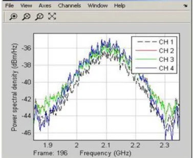
In figure 2, The RF repeater which will gain the weak signal an enough power to reach the nominal operating power for the mobile equipment based on the standard is presented. Now, a four cell phones repetition system with different sensitivities is designed to examine what happened for its frequency response if the random signal is the same, then what’s happening when the frequency is 1800 MHz and 2100 MHz, in figure 3. The overall system behavior is shows in figure 4 and we can conclude that:
1-In the first three systems, an amplifier with S-parameters data file, we have tried more than one type of the Transmission line to see which type of Transmission line gives the best result. 2-The fourth system represents the amplifier itself.
3. the power spectral density of the four system was at the minimum values at 1800 MHz but it has the maximum values at 2100 MHz, which means if you are at low space coverage (low density of received power) and your cell phone is designed to make switching between GSM and 3G, turn the power switch to 3G your cell phone will be better.
4-Each color represents one of the systems above, and you can see that the Best system that has the largest power spectral density is the First one.
In this simulation method, the RF system is considered as a transceiver system. Now, we proposed a new system by improving the performance of the cell phone transmitter figure 5 by treatment of the sent signal using two parallel branches one of them using LC high-pass filter and in the same time we make filtration via LC low-pass filter, then we added of them after passed scatter parameters.
At receiver figure 6, only LC band-pass filter is employed, when we make full analysis in the transmitter. It is found that the cutoff frequency of HPF and LPF are the same of the two boundaries of the BPF of the receiver but the last stage of receiver is divider the filtered amplified signal into high and low bands using sub-band filter to ease the sub-band source coding. Figure 5.9 is the simulation result of the output Signal of the receiver; notice that the magnitude of the received power is increased at 1800 MHz compared to figure 4.
.
Fig.2. RF repeater Matlab-Simulink model.
Fig. 4. Simulation results of frequency responses for four RF systems ranging from 1.85 GHz to 2.35 GHz.
Fig. 7. Output signal of the RF receiver.
Fig. 6. RF Receiver model.
V.CONCLUSIONS
In this paper, a design and building a synthesis circuit system including filters with an analog repeater to avoid the space coverage problem in cell phone network is presented. The proposed system was intended for Saudi Arabia cellular
service networks, which use the 1.8 and 2.1 GHz portions of the radio spectrum. The system was modeled using Matlab-Simulink software package. The simulation results show the effectiveness of the proposed design.
Base up on the obtained results:
- The manufacturer of the mobile devices needs to improve their cell phone by separate the power meter and the RF oscillator into 2G and 3G by switch. If the user feels that he cannot make a phoning call, he can make manual switching between 2G and 3G frequencies not depending on the power meter reading of the cell phone.
- If the manufacturer not prefer this above solution, we proposed an improving full synthesis and analysis networks inside cell phone transmitter and receiver using LC filters (HPF, LPF, and BPF) with scattering parameter amplifier . - The values of the inductor and capacitor inside filters should be calculated carefully.
- This method decrease the healthy effect of the cell phone on the human .
REFERENCES
[1] Daniel Baumann,”Minimization of Drive Tests (MDT) in Mobile Communication Networks”Seminars FI / IITM WS 13/14, Network
Architectures and Services, March 2014, doi: 10.2313/NET-2014-03-1_02
[2] Lei Chen, “Performance Engineering of Mobile Broadband -Capacity Analysis, Cellular Network Optimization, and Design of In-Building Solutions”, Linkoping studies in science and technology, dissertations, no. 1504, 2013.
[3] Rasmi Ranjan Patra, and Prashanta Kumar Patra,” Analysis of k-Coverage in Wireless Sensor Networks” International Journal of Advanced Computer Science and Applications, Vol. 2, No. 9, 2011.
[4] Fanimokun, A. and J. Frolik, “Effects of Natural Propagation Environments on Wireless sensor Network Coverage Area,” 2003 IEEE Southeastern Symposium on System Theory (SSST03), Morgantown, WV, Mar. 16-18.
[5] Rodney Van Meter “A brief survey of current work on network attached peripherals”, ACM SIGOPS Operating Systems Review, Volume 30 Issue 1, Pages 63-70 Jan., 1996.
[6] Von Eicken, T., Vogels, W.: “Evolution of the Virtual Interface Architecture”,IEEE Computer, pp. 61-68, Nov., 1998.
[7] Leijten J.A.J.: “Real-time constrained reconfigurable communication between embedded processors”, Ph.D. thesis, Eindhoven University of Technology, November 1998.
[8] Z. Fluhr and E. Nussbaum, "Switching Plan for a Cellular Mobile Telephone System":, , IEEE Transactions on Communications volume 21, #11 pp. 1281, 1973.
[9] Hachenburg, V.; Holm, B.D.; Smith, J.I. "Data signaling functions for a cellular mobile telephone system". IEEE Transactions on Vehicular Technology, pp. 82-88, 1977.
[10] Matlab-Simulink software package link: http://www.mathworks.com/products/simulink/
Author’s profiles,
Majed O. Dwairi: An associate professor in the department of Electrical Engineering, faculty of Engineering Technology Amman - Marka, Jordan. Currently, he is an associate professor in the faculty of Engineering, Taif University, Saudi Arabia. His research interests include optical communication networks, digital communications modelling systems, multichannel communications, multilevel modulation technique, Antenna design, microstrip patch antennas, Dielectric Resonant antennas, optimization techniques and antenna measurement techniques.
Dr. Dwairi is the head of Radio and Wireless Club (RWC) in Taif University, Saudi Arabia.
Mohamed S. Soliman: An assistant professor in the department of Electrical Engineering, faculty of Energy Engineering, Aswan University, Egypt. Currently, he is with the department of Electrical Engineering, Faculty of Engineering Taif University, Saudi Arabia. His research interests include wireless communications, phased and timed array signal processing, UWB microstrip patch antennas, Dielectric Resonant antennas, numerical methods in electromagnetics, optimization techniques in antenna design and antenna measurement techniques.
Dr. Soliman is a member of the IEEE-AP Society, KAUST chapter, Saudi Arabia.
Jawdat S. Alkasassbeh: was born in April, 1983 in Jordan. He received his B.Sc. in Communications Engineering, department of Electrical Engineering, faculty of Engineering, Mu’tah University, Jordan in 2006. He had the master degree in Communications Engineering from the University of Jordan in 2011. Currently, he is a lecturer at Electrical Engineering Department, Albalqa’a Applied University, Jordan. His research interests include mobile communications, digital wireless communication systems, radio link design, and adaptive modulation techniques.