Induced activation in accelerator components
Cristian Bungau,* Adriana Bungau, Robert Cywinski, Roger Barlow, and Thomas Robert Edgecock
University of Huddersfield, School of Applied Sciences, Huddersfield, HD1 3DH, United Kingdom
Patrick Carlsson, Håkan Danared, and Ferenc Mezei
European Spallation Source, Lund, Sweden
Anne Ivalu Sander Holm, Søren Pape Møller, and Heine Dølrath Thomsen
ISA, Aarhus University, 8000 Aarhus C, Denmark (Received 26 September 2013; published 18 August 2014)
The residual activity induced in particle accelerators is a serious issue from the point of view of radiation safety as the long-lived radionuclides produced by fast or moderated neutrons and impact protons cause problems of radiation exposure for staff involved in the maintenance work and when decommissioning the facility. This paper presents activation studies of the magnets and collimators in the High Energy Beam Transport line of the European Spallation Source due to the backscattered neutrons from the target and also due to the direct proton interactions and their secondaries. An estimate of the radionuclide inventory and induced activation are predicted using the GEANT4 code.
DOI:10.1103/PhysRevSTAB.17.084701 PACS numbers: 29.25.Rm
I. INTRODUCTION
Activation induced by particle nuclear interactions in beam line components represents one of the main radiation hazards of high-energy accelerators. Although elements such as targets, collimators, magnets, and beam dumps are built to withstand radiation, they become themselves highly radioactive as a result of induced activation. Induced radioactivity is due either to direct interactions of the incoming beam or indirect interactions of secondary particles in the accelerator components leading to radio-nuclides production. This activation causes remnant ambi-ent dose rates inside accelerator tunnels and target areas but also means that when components are being replaced at the end of their operational lifetime, they must be treated as radioactive waste. Large quantities of activated material arise when the whole accelerator is decommissioned as dismantling it will pose a major challenge for radiation protection. Exposure to radiation from induced activation can occur in connection with handling, transport, machin-ing, weldmachin-ing, chemical treatment, and storage of irradiated items. These procedures can be extremely difficult because the accumulated doses can exceed the permitted limits and remote handling becomes necessary. In the field of radio-active materials and waste there are no internationally agreed recommendations while in radiation protection the
dose limits are dependent on the national regulations. Both the International and European Basic Safety Standards[1]
only contain tables with radionuclide specific exemption limits[2]and do not make recommendations with respect to the clearance of radioactive material.
Because the accelerator components reveal high induced activation during normal operations and after accelerator shutdown, it is of primary importance to predict correctly their radionuclide inventory and residual activity before any handling and maintenance procedures. The technical challenge is first to ensure that the beam losses are small as residual activity depends greatly not only on material properties but also on the amount of beam loss. The main causes of beam loss in high-current accelerators are (i) space charge effects that arise due to Coulomb repulsion between particles; the Coulomb repulsion becomes more important as the beam current is increased and causes an increased emittance leading to beam losses; (ii) beam halo surround-ing the beam core, caused by space charge induced emittance growth; (iii) emittance increase which could be due to several reasons like space charge effects, non-linear resonances, chromatic aberrations in lenses; (iv) backstreaming neutrons coming from the target on the beam pipe; (v) mismatch of the beam across accelerator elements transitions; and (vi) low aperture to rms beam size ratio; this should be kept reasonably high to prevent the beam from hitting elements and getting lost.
The high-energy protons lost along the beam line generate secondary neutrons by spallation and these in turn activate the accelerator components through which they pass. Different nuclear fragments can be emitted as well converting the nucleus to an isotope most probably of
*
Published by the American Physical Society under the terms of
the Creative Commons Attribution 3.0 License. Further
distri-bution of this work must maintain attridistri-bution to the author(s) and
a different element with a high chance of being radioactive. The radionuclides that are produced are unstable and undergo radioactive decay. Although the induced radio-activity will depend on the beam loss history including cool down history, the probability of producing a particular isotope will also depend on the composition of the material struck, the spectrum of secondaries produced, and the production cross section of the isotope concerned[3].
The spallation reactions take place in two steps: a fast nuclear cascade followed by a slow evaporation process. In the first step the high-energy particle entering the nucleus is capable of knocking out one or more nucleons or even a fragment of the target nucleus. Another part of the projectile energy is transferred to the remaining nucleons which subsequently collide with each other, distributing the energy almost equally and in this way a cascade develops. Some of the nucleons reach the nuclear boundary and get lost; others are caught and distribute their kinetic energy among the remaining nucleons in the nucleus. The intra-nuclear cascade leads finally to a highly excited nucleus. The intranuclear cascade stage is not distinctively separated from the deexcitation stage and the preequilibrium emis-sion follows. In this intermediate stage fast particles are emitted. In the deexcitation stage the remnant nucleus loses its residual excitation energy by evaporation processes emitting neutrons and low energy light particles (protons, deuterons, alpha particles). Some of the nucleons may leave the nucleus if their energy is higher than their binding energy. Nucleons at the surface in a less strongly bound state have binding energies of a few MeV, whereas nucleons in the deeper-lying shells need about 50 MeV to remove them from the nucleus. Charged particles such as protons and pions (produced mainly in the decay of the Delta resonance) have to overcome the Coulomb barrier in addition. If they overcome the strong force field of the nucleus, they even get additional energy. When the nucleus does not have enough energy to emit neutrons it deexcites by emitting gamma rays. At the end of this process the resulting nucleus is usuallyβ radioactive (although a bias to the production of αemitters exists for high A nuclei) and decays until it becomes stable. The disintegration is a random process being defined by the half-life of the produced radionuclides. Radioisotopes with a short lifetime of a couple of minutes can be considered as bringing no contribution to the residual radiation studies. The total number of the disintegrations of all sorts occurring per unit time represents the activity of the activated material.
II. ACTIVATION FORMULA
The nuclear reactions are characterized quantitatively by their cross section. Assuming that the cross sectionsσT;νof the possible nuclear reactions of converting a target nucleus
T into an isotopeν are known, the number of radioactive nuclei of isotopeνper gram of target material produced per unit time is
nν¼ΦN0 AT
σT;ν; ð1Þ
whereΦ is the fluence rate of projectile particles defined as the number of particles incident on a sample per unit surface, per second,N0 is Avogadro’s number, AT is the
mass number of the target material, and σT;ν is the integrated cross section over the whole fluence spectrum. Once the radioactive nuclei have been produced, their number decays exponentially with time. Taking into account both the production rate nν and the decay rate,
we can write
dNν
dt ðtÞ ¼nν−λνNνðtÞ; ð2Þ
whereλνis the decay constant of isotopeνandNνðtÞis the
number of nuclei ν as a function of time. If the target is irradiated during the irradiation time ti, the number of
radioactive nucleiNνðtiÞ of an isotopeν is
NνðtiÞ ¼Φ
N0
λνAT
σT;νð1−exp½−λνtiÞ: ð3Þ
From Eq. (3)the activity after a cooling timetc can be
obtained as
−dNν
dtc
¼ΦN0
AT
σT;νð1−exp½−λνtiÞexp½−λνtc: ð4Þ
This is the activation formula for one isotope that gives the disintegration rate of that particular isotopeνin one gram of target materialT which has been irradiated during a timeti
and left to decay during a timetc. The total specific activity
of the target material will be the sum of the specific activities of all the particular isotopesνproducible. Although this is a simplified approach not considering daughter production, in the later chapter where we simulate the isotope production, when calculating the production rate we will take into account not only the production due to the direct interaction of various particles with the elements [Eq.(1)] but also the contribution to the production rate due to the decay of other isotopes produced in these interactions.
III. THE GEANT4 MODEL
Owing to the complexity of the spallation reactions that take place inside the material of the accelerator compo-nents, a proper analytical treatment is hardly possible. Spallation reactions are complicated processes with many reaction channels and gamma spectroscopy for radionu-clide identification proved in many cases to be not sufficient; therefore, Monte Carlo techniques are used to quantify the radioisotopes produced. One can apply the Monte Carlo method to the theoretical reaction model and thereby predict the outcome of the spallation reactions and then sum over all production channels to give an estimate of the total activity. The GEANT4[4]code has been used in the current simulations to predict the spallation reaction products and to calculate the activity induced. It tracks the incident particle and simulates its interactions with nuclei of the material as well as the production of the secondary particles and their interactions. The geometry of the system and the characteristics of the particle beam must be also modeled in the code.
GEANT4 provides an extensive set of hadronic physics models for energies up to 10–15 GeV, both for the intranuclear cascade region and for modeling the evapo-ration processes. There are many different (data-based, parametrized, and theory-driven) models using different approximations and each has its own applicable energy range. Monte Carlo codes usually come with their own physics models and the user is offered default selections. Because of the vast range of applications, GEANT4 will not give the users any default physics models; the users themselves have to work out what models to use for what processes. In order to model the proton and neutron inelastic interactions in the energy range relevant for this study, the best physics models available are the three theoretical intranuclear cascade models provided by GEANT4: INCL/ABLA (Liégé) model, Binary cascade, and the Bertini model. The Liégé intranuclear cascade model together with the independent evaporation/fission code ABLA have been validated against experimental data for spallation processes in many different heavy elements
[5]. However, the INCL/ABLA validation results presented at the IAEA benchmark for spallation reactions show that, for energies lower than 150 MeV, the results of the Liégé model are not so good as above this energy [6]. This is because the model does not have preequilibrium: INCL cascade is directly “coupled” to equilibrium deexcitation handled by ABLA and therefore it does not describe well enough low energy reactions (where nuclear structure effects start to play their role). Above 150 MeV, INCL/ ABLA works very well, being one of the best models available. On the other hand, the other two models available in GEANT4, Bertini and Binary cascade, do incorporate the preequilibrium model. The preequilibrium model in GEANT4 has been recently improved following a valida-tion study against the transmutavalida-tion by adiabatic resonance
crossing (TARC) experiment data, in order to improve several shortcomings in applying this model to neutron spallation processes [7]. All these recent developments have been considered and implemented in our code.
For the simulations presented in this paper, the Bertini model was selected. For neutron energies below 20 MeV, the high-precision models were selected. These models use the ENDF/B-VII[8], JENDL[9], MENDL-2[10]and other data libraries [11]. The Sðα;βÞ [12,13] coefficient, which takes into account the corrected treatment for neutron scattering on chemically bound elements in the thermal region, has also been implemented in the GEANT4 physics list used for this study.
IV. RESULTS
The change in the lattice structure of the materials that are irradiated lead to the failure of the components and recently there has been a renewed interest in the topic of radiation damage as high-power accelerators are required for physics experiments. One such accelerator is the European Spallation Source (ESS) which will be built in Lund, Sweden. This is a high-power (5 MW) proton accelerator that will produce high-intensity neutron beams through spallation. It is therefore essential to know what the residual dose rates will be in the most exposed elements like magnets and collimators placed in the close proximity of the target; therefore simulations had to be performed.
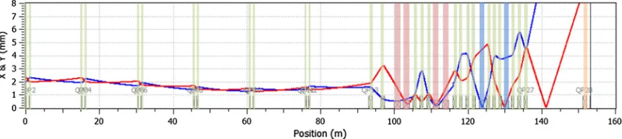
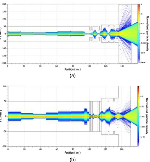
The HEBT-S1 is followed by a semivertical bending section denoted HEBT-S2 bringing the beam from the underground linac tunnel to the target, 1.6 m above ground level. The third horizontal section (HEBT-S3) includes the expansion system to provide the requested beam footprint at the target while keeping the peak current density minimal. The last section is a short horizontal section for a beam dump to be used for accelerator tuning and commissioning. The HEBT-S3 components were modeled in the GEANT4 simulation code since the elements of this particular beam line are the ones at risk because of the backstreaming neutrons coming from the target. HEBT-S3 is designed in order to fulfil the requirements for the beam footprint and peak current density at the target. In order to obtain a peak current density of less than64μA=cm2inside the requested footprint (160×60mm) while keeping the power deposited outside the footprint low, octupoles are utilized. Downstream of the last octupole, three quadrupoles are placed in order to spread the now folded beam over the desired footprint area. The input particle distribution is a superposition of two 6D Gaussian distributions, a core and a halo distribution, with widths determined by the linac output (1.90 mm horizontally and 2.74 mm vertically)[16]. The baseline rms envelopes are shown in Fig. 2 and the horizontal and vertical particle densities along the HEBT in Figs.3(a) and3(b).
A. Radionuclides inventory in the HEBT-S3 magnets and collimators
Beam losses will inevitably occur along the HEBT line. These losses originate from weak tails of beam lost over
long operation periods in both transverse and longitudinal planes or short pulses (until the beam is shut down) of the main beam impacting major components. Experience has shown that activation caused by uncontrolled beam losses uniformly distributed along the beam line of1W=m can be accepted for high-energy proton accelerators as a threshold for the hands-on maintenance [17]. Therefore the proton beam losses at the European Spallation Source were established to be on the average lower than 1W=m. This value was used to calculate the direct beam impact on the magnets. We considered the direct impact of all the secondaries produced in the interactions between the incident protons and the beam pipe, as well as inside each element. At the collimator the beam losses are around 20 kW [18]. This value was used to simulate the direct beam impact effect on the particle collimator.
The HEBT line includes a large number of magnets with associated power supplies, and both normal conducting magnets as well as high-temperature superconducting mag-nets are considered for this beam line. The parameters for the elements in the HEBT line are given in the TableI.
[image:4.612.75.534.46.146.2]The effect of the backscattered neutrons from the target on various magnets along the beam line (Fig.4) has been considered in our activation calculations. The aperture of the octupole is reduced compared to the rest of HEBT magnets to obtain large field derivatives for a limited pole tip field[16]. This will unavoidably lead to higher losses at this element as compared to the upstream HEBT elements; however, these losses are expected to be small compared to the amount of neutrons from the target. Regarding the
[image:4.612.84.530.205.305.2]radioactive inventory originating from accelerator compo-nents experience has shown that the gamma emitting isotopes are dominant along with the relatively short-lived beta isotopes. Therefore, in order to study the beam line components activation, the code has been designed to register the production of any radioactive isotope that decays emitting gamma rays and also that has a lifetime longer than 24 hr. Shorter lived isotopes, like 24Na for example, can pose a safety concern if the tunnel has to be accessed in emergency situations, but we limited our study to include only the isotopes that live longer than 24 hr. Therefore the isotopes that are recorded by our simulation code are 7Be, 46Sc, 44Ti, 51Cr, 54Mn, 59Fe, 56Co, 57Co,
58Co,60Co,65Zn,75Se,84Rb,85Sr,88Y,95Zr,94Nb,95Nb, 106Ru, 109Cd,111In,113Sn,125Sn,124Sb,125Sb,125I,132Cs, 134Cs, 137Cs, 133Ba, 139Ce, 141Ce, 144Ce, 152Eu, 154Eu, 153Gd, 160Tb, 161Tb, 170Tm, 169Yb, 172Hf, 182Ta, 185Os, 192Ir, 198Au, 199Au, 203Hg, 210Pb, 207Bi, 228Th, 239Np, 241Am, and 243Am. One of the factors that contributes to
the production of these isotopes inside the magnets is the
direct impact of the proton beam. When proton beam losses occur, the protons interact with the beam pipe producing hadronic and electromagnetic showers. Also when the protons interact with the magnets they will produce addi-tional secondaries. We looked at all the secondaries that produce one of the isotopes of interest and Fig.5 shows the number of each secondary particle that creates these isotopes per lost proton. It can be seen that even when considering only the direct proton beam interactions, the main contribution to the induced activation comes from the secondary neutrons produced either in the beam pipe or in the magnets. In fact the contribution of the secondary neutrons is about 3 times higher than the contribution of the lost protons.
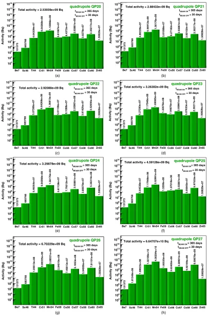
The radioactive decay processes have been added to the standard physics list provided by GEANT4, such that the production rate takes into account not only the isotopes produced by the direct impact of incoming protons and by the backscattered neutrons on various accelerator compo-nents, but also the production of these isotopes following the decay of other isotopes produced in these interactions. Apart from the geometry of the magnets shown in Fig. 1, the material composition also has to be known. For simplicity, the magnets were assumed in the simula-tions to be made of a homogeneous mixture of Fe and Cu in equal proportions. It is still an open question whether the magnets are suspended or supported and surely there will be some mechanical stainless steel structure holding each magnet in place. The radionuclide inventory present in the HEBT-S3 octupoles (OCT1 and OCT2) is presented in Fig. 6. The radioactive nuclide inventory of each of the HEBT-S3 quadrupoles is presented in Fig.7. The isotope yield shown in these figures represents the total amount of a particular isotope given by direct proton interactions, backscattered neutrons, and also by secondary neutron interactions and other secondary interactions. There is a higher amount of isotopes produced by direct proton impact and its secondaries in the quadrupoles placed at the beginning of the HEBT-S3 beam line while for the quadrupoles placed in the close proximity of the target the isotopes produced by backscattered neutrons are predomi-nant. In all octupoles and quadrupoles, the isotopes51Cr and54Mn are predominant although there are also signifi-cant amounts of isotopes57Co, 58Co, and 60Co.
[image:5.612.56.297.43.303.2]Eventual beam tails formed in the HEBT will be caught by a set of fixed collimators just before the proton beam window in order to protect the edges of both the proton beam window and the main target. These collimators are copper cylinders of 1 m length with a diameter of 2 m and they have a rectangular opening of ð16×6Þcm. The copper collimators are coated with tungsten. Being placed in front of the target monolith, the collimators are the most radioactive elements in the beam line and therefore they will be exposed to a high flux of backstream neutrons coming from the target and will be at high risk due to the
TABLE I. Parameters of the HEBT elements.
Element Length (mm) Aperture (mm) Strength (T)
Dipoles 1570 40×80(total gap) 1.47
Quadrupoles 400 or 800 40 (radius) 0.48
Octupoles 800 25 (radius) 0.35
[image:5.612.52.298.657.715.2]their position in the beam line. The radionuclide yields produced inside the Cu core and the W coating are shown separately in different colors in Fig.8. The isotope yield is expressed per incoming proton and isotopes produced in all four mechanisms (by direct proton impact, by back-scattered neutrons, by secondary neutron interactions, and other secondary interactions) are shown separately. Examination of the isotope chart shows a higher yield of all isotopes found in the magnets (7Be,46Sc,44Ti,51Cr,54Mn,
59Fe,56Co,57Co,58Co,60Co,65Zn). There is a large range
of other isotopes produced in a significant amount (i.e.,
109Cd, 111In, 113Sn,172Hf, 182Ta).
The isotopes found in the magnets and in the collimator are listed in Table II together with their half-lives, decay mode, and the level of gamma radiation they emit expressed as the gamma dose rate at 1 m when the decay rate is 1 Bq [19]. The radioactive isotopes may decay by beta (β−) emission or when proton rich isotopes are produced by positron (βþ) emission. In some cases the nucleus decays by capturing an orbiting electron. The
daughter nucleus resulting from decay may deexcite by emitting gamma radiation. It can be seen from the table that a number of isotopes like 241Am, 243Am, 133Ba, 207Bi,
109Cd,134Cs, 137Cs,152Eu,154Eu,44Ti,60Co, 94Nb,210Pb,
0.120481
0.396607
0.0421216
0.0262351
0.000111662
0.000414244 0.000570137
0.000129799
3.94774e-05
1.43138e-05 2.20263e-05
4.60785e-06
5.59481e-05
1.4706e-05
1.01307e-06 1.37255e-06 1.69935e-06
protonneutronpi- pi+ mu- gammadeuterontriton kaon+sigma-alphakaon0Skaon0LHe3 e+ e- kaon--6
10 -5 10
-4 10
-3 10
-2 10
-1 10
1 10
[image:6.612.122.499.52.184.2]particles / lost proton
FIG. 5. Contribution of each particle type to the magnets activation due to proton beam losses in the beam pipe.
Be7 Sc46 Ti44 Cr51 Mn54 Fe59 Co56 Co57 Co58 Co60 Zn65
Isotopes / proton
0 0.02 0.04 0.06 0.08 0.1 0.12
7.85266e-12 2.73865e-09
5.517e-09
5.08286e-08
9.67813e-08
9.19055e-09
5.79337e-09
1.81453e-08
1.39356e-08
2.29464e-08
8.99226e-10
Octupole OCT1
Be7 Sc46 Ti44 Cr51 Mn54 Fe59 Co56 Co57 Co58 Co60 Zn65
Isotopes / proton
0 0.02 0.04 0.06 0.08 0.1 0.12 0.14
-6
10
× -6
10
×
7.85266e-12 2.73865e-09 5.517e-09
6.67017e-08
1.20591e-07
1.1836e-08
5.79337e-09
2.34363e-08
1.39356e-08
3.08829e-08
8.99226e-10
inside octupole OCT2 (a)
[image:6.612.314.560.296.641.2](b)
[image:6.612.55.293.508.682.2]Be7 Sc46 Ti44 Cr51 Mn54 Fe59 Co56 Co57 Co58 Co60 Zn65
Isotopes / proton
0 10 20 30 40 50 60 -9 10 × 4.53178e-12 1.601 1 9e-0 9 3.24603e-09 3.27383e-08 4.54952e-08 1.95414e-09 3.35077e-09 1.03807e-08 7.9387e-09 9.94849e-09 5.22533e-10 quadrupole QP20
Be7 Sc46 Ti44 Cr51 Mn54 Fe59 Co56 Co57 Co58 Co60 Zn65
Isotopes / proton
0 10 20 30 40 50 60 70 80 90 -9 10 × 4.53178e-12 1.601 1 9 e -0 9 3.24603e-09 2.74473e-08 6.40137e-08 1.95414e-09 3.35077e-09 1.03807e-08 7.9387e-09 9.94849e-09 5.22533e-10 quadrupole QP21
Be7 Sc46 Ti44 Cr51 Mn54 Fe59 Co56 Co57 Co58 Co60 Zn65
Isotopes / proton
0 10 20 30 40 50 60 70 80 -9 10 × 4.53178e-12 1.601 1 9e-0 9 3.24603e-09 3.27383e-08 5.60772e-08 1.95414e-09 3.35077e-09 1.03807e-08 7.9387e-09 1.52395e-08 5.22533e-10 quadrupole QP22
Be7 Sc46 Ti44 Cr51 Mn54 Fe59 Co56 Co57 Co58 Co60 Zn65
Isotopes / proton
0 0.02 0.04 0.06 0.08 0.1 -6 10 × 4.53178e-12 1.60 1 1 9e -0 9 3.24603e-09 3.53838e-08 6.93047e-08 4.59964e-09 3.35077e-09
1.03807e-08 1.05842e-08 9.94849e-09
5.22533e-10
quadrupole QP23
Be7 Sc46 Ti44 Cr51 Mn54 Fe59 Co56 Co57 Co58 Co60 Zn65
Isotopes / proton
0 10 20 30 40 50 60 70 80 90 -9 10 × 4.53178e-12 1.601 1 9e-09 3.24603e-09 3.27383e-08 6.40137e-08 1.95414e-09 3.35077e-09 1.03807e-08 7.9387e-09 2.3176e-08 5.22533e-10 quadrupole QP24
Be7 Sc46 Ti44 Cr51 Mn54 Fe59 Co56 Co57 Co58 Co60 Zn65
Isotopes / proton
0 0.02 0.04 0.06 0.08 0.1 0.12 0.14 -6 10 ×
4.53178e-12 1.601
1 9e -09 3.24603e-09 3.53838e-08 1.03696e-07
4.59964e-09 8.64178e-09 1.03807e-08 1.05842e-08
2.58215e-08
5.22533e-10
quadrupole QP25
Be7 Sc46 Ti44 Cr51 Mn54 Fe59 Co56 Co57 Co58 Co60 Zn65
Isotopes / proton
0 0.02 0.04 0.06 0.08 0.1 0.12 0.14 0.16 0.18 0.2 0.22 -6 10 × 4.53178e-12 1.601 1 9 e -0 9 5.89154e-09 4 .861 1 4 e -0 8 1.59252e-07 9.89065e-09 3.35077e-09 1.83172e-08 1.05842e-08 3.3758e-08 5.22533e-10 quadrupole QP26
Be7 Sc46 Ti44 Cr51 Mn54 Fe59 Co56 Co57 Co58 Co60 Zn65
Isotopes / proton
0 0.2 0.4 0.6 0.8 1 1.2 1.4 1.6 1.8 2 2.2 -6 10 ×
4.53178e-12 4.24669e-09 5.89154e-09
5.03638e-07
1.64073e-06
6.80917e-08 1.65783e-08 1.26783e-07 1.24341e-07
[image:7.612.109.504.42.653.2]4.1471e-07 5.22533e-10 quadrupole QP27 (a) (b) (c) (d) (e) (f) (g) (h)
106Ru,125Sb, and172Hf pose significant risks for radiation
protection as their half-life is more than one year.
B. Activation of the magnets and collimators
The number of isotopes producedNisoinside the
HEBT-S3 accelerator components gives the production rate for each isotope. This production rate takes into account the direct impact of the proton beam on each accelerator component due to the proton beam spatial distribution, the interactions of the backscattered neutrons, and the isotopes production following the decay of other isotopes produced in these interactions. All these processes have been considered when counting Niso in the simulations
output. The activation formula given in Eq. (4)offers the general theoretical approach in estimating the induced activity and relies on the knowledge and use of the cross section σT;ν of the inelastic process in which the target nucleus T turns into the isotope ν. However, in the GEANT4 code these cross sections are included in the database and the code can predict directly the numberNiso
of isotopes produced in these processes such that the user does not have to use each inelastic process cross section in
order to calculate the induced activity. The production rate for each isotope NisoΔt is simulated taking into
account direct proton impact, backscatted neutrons, sec-ondary interactions, and decay of other isotopes produced in these interactions.
GEANT4 calculates the isotope production using beside the particle induced production also the full Bateman solution considering the breeding of radioactive decay products. The majority of the radionuclide production is coming from the particle impact induced activation and only a smaller fraction from decay production. Therefore considering the production rate for radioactive isotopeνto be constant in time is a good estimate for the real situation. The production rate for a radioactive isotope is given by
dNprodν
dt ¼
Niso
Δt ¼ NisoI
Npe
; ð5Þ
where Niso is the number of isotopes produced, I is the
proton beam current from the accelerator,Npis the number
of incident protons, and e is the proton electric charge. Once the radioactive nuclei have been produced, their
8.0402e-09 1.4302e-05 3.48298e-05 9.14726e-05 3.77162e-05 1.41731e-05 2.85662e-05 0.000141462 8.79402e-05 5.31557e-05 2.8324e-05
Be7 Sc46 Ti44 Cr51 Mn54 Fe59 Co56 Co57 Co58 Co60 Zn65 Se75 Rb84 Sr85 Y88 Zr95 Nb94 Nb95 Ru106 Cd109 In111 Sn113 Sn125 Sb124 Sb125 I125 Cs132 Cs134 Cs137 Ba133 Ce139 Ce141 Ce144 Eu152 Eu154 Gd153 Tb160 Tb161 Tm170 Yb169 Hf172 Ta182 Os185 Ir192 Au198 Au199 Hg203 Pb210 Bi207 Th228 Np239 Am241 Am243 -11 10 -10 10 -9 10 -8 10 -7 10 -6 10 -5 10 -4 10 -3 10 -2 10 -1 10 1
Isotopes produced inside collimator
Cu
due to direct proton interactions
2.20436e-08 2.56616e-08 8.0938e-08 3.06868e-08 7.03518e-09 9.71524e-09 4.79062e-08 3.56449e-08 1.42714e-08 5.95645e-08 4.83752e-08 1.81575e-08 9.57454e-08 5.21943e-08 1.00503e-09 2.34506e-08 1.43384e-08 2.07705e-09 1.3202e-06 1.42184e-06 3.83766e-06 6.70017e-11 7.30318e-09 3.8191e-09 3.55109e-07 2.97487e-08 1.87605e-09 1.86332e-07 2.92127e-08 2.27806e-09 1.34003e-10 1.78894e-08 2.54606e-09 1.27504e-07 2.47906e-09 1.47404e-09 8.60972e-08 8.99431e-07 6.64657e-06 6.35906e-06 6.70017e-11 W 6.70017e-11 4.45018e-06 6.9931e-06 7.59992e-05 6.3487e-05 5.16421e-05 5.91664e-05
0.000425519 0.000364107 0.000581756
Be7 Sc46 Ti44 Cr51 Mn54 Fe59 Co56 Co57 Co58 Co60 Zn65 Se75 Rb84 Sr85 Y88 Zr95 Nb94 Nb95 Ru106 Cd109 In111 Sn113 Sn125 Sb124 Sb125 I125 Cs132 Cs134 Cs137 Ba133 Ce139 Ce141 Ce144 Eu152 Eu154 Gd153 Tb160 Tb161 Tm170 Yb169 Hf172 Ta182 Os185 Ir192 Au198 Au199 Hg203 Pb210 Bi207 Th228 Np239 Am241 Am243 -11 10 -10 10 -9 10 -8 10 -7 10 -6 10 -5 10 -4 10 -3 10 -2 10 -1 10
1 Isotopes produced inside collimator
Cu
due to secondary neutrons interactions
6.70017e-11
2.01005e-10 2.01005e-10 6.70017e-11 1.34003e-10 6.70017e-117.9732e-09
3.35008e-10 2.01005e-10 2.68007e-09 3.08208e-09 9.91625e-09 1.34003e-10 2.81407e-09 2.01005e-10 3.08208e-09 8.71022e-10 6.70017e-11 1.20603e-09 6.70017e-11 9.51424e-09 2.01005e-10 6.70017e-11 2.21106e-08 3.96449e-07 9.74459e-06 5.07421e-05 W 5.86265e-08 2.013e-06 3.06908e-06 3.35866e-05 4.32418e-05 1.32965e-05 2.06992e-05 8.1869e-05 7.04964e-05 3.92779e-05 2.38405e-06
Be7 Sc46 Ti44 Cr51 Mn54 Fe59 Co56 Co57 Co58 Co60 Zn65 Se75 Rb84 Sr85 Y88 Zr95 Nb94 Nb95 Ru106 Cd109 In111 Sn113 Sn125 Sb124 Sb125 I125 Cs132 Cs134 Cs137 Ba133 Ce139 Ce141 Ce144 Eu152 Eu154 Gd153 Tb160 Tb161 Tm170 Yb169 Hf172 Ta182 Os185 Ir192 Au198 Au199 Hg203 Pb210 Bi207 Th228 Np239 Am241 Am243 -11 10 -10 10 -9 10 -8 10 -7 10 -6 10 -5 10 -4 10 -3 10 -2 10 -1 10
Isotopes produced inside collimator
Cu
due to other secondaries interactions
6.70017e-10
1.34003e-10 2.01005e-10
6.70017e-11
2.01005e-10 3.35008e-10 6.70017e-11 6.70017e-11 6.70017e-11
2.01005e-10
6.70017e-11
4.0201e-10
6.70017e-11
9.38023e-10
4.0201e-10 4.0201e-10 3.35008e-10 3.35008e-10
1.67504e-09 8.0402e-10 1.34003e-10 6.70017e-10 3.35008e-10 6.70017e-10 1.34003e-10 4.55611e-09 3.35008e-10 4.0201e-10 1.67839e-07 1.30265e-06 6.56101e-06 3.10915e-06 3.41709e-08 W 2.6455e-09 1.87831e-07 1.16402e-07
6.88095e-06 1.34974e-05 1.41984e-05 1.30767e-05 0.00011828 0.000124394
0.000486579
3.83333e-06
Be7 Sc46 Ti44 Cr51 Mn54 Fe59 Co56 Co57 Co58 Co60 Zn65 Se75 Rb84 Sr85 Y88 Zr95 Nb94 Nb95 Ru106 Cd109 In111 Sn113 Sn125 Sb124 Sb125 I125 Cs132 Cs134 Cs137 Ba133 Ce139 Ce141 Ce144 Eu152 Eu154 Gd153 Tb160 Tb161 Tm170 Yb169 Hf172 Ta182 Os185 Ir192 Au198 Au199 Hg203 Pb210 Bi207 Th228 Np239 Am241 Am243 -11 10 -10 10 -9 10 -8 10 -7 10 -6 10 -5 10 -4 10 -3 10 -2 10 -1 10
1 Isotopes produced inside collimator
Cu
due to backscattered (target) neutrons
[image:8.612.58.559.42.362.2]1.32275e-08 4.52381e-07 4.91534e-06 W (a) (b) (c) (d)
number decays exponentially with time. During the beam-on period, the time evolutibeam-on can be obtained by combining the production and decay rates:
dNν dt ðtÞ ¼
NisoI Npe
−λνNνðtÞ: ð6Þ
We consider first the boundary condition of having at
t¼0 a nonradioactive material. The solution of Eq. (6)
gives the number of isotopes at any timetduring the beam exposure:
NνðtÞ ¼ NisoI Npeλν
½1−expð−λνtÞ: ð7Þ
However, after the beam is switched off, following a continuous exposure for a given time t1, the number of
isotopes after a time t, which includes both the beam-on periodt1 as well as the beam-off period, is given by
NνðtÞ ¼ NisoI Npeλν
½1−expð−λνt1Þexp½−λνðt−t1Þ: ð8Þ
The induced activity for an accelerator element given by one particular isotope is given by Eq.(9):
AνðtÞ ¼λνNνðtÞ: ð9Þ
Using Eqs. (8) and (9), the activity of each isotope produced is given by Eq. (10)at any given time twhich includes the beam-on time t1 and the beam-off period
(during the beam-on period,t¼t1),
AνðtÞ ¼NisoI Npe
½1−expð−λνt1Þexp½−λνðt−t1Þ: ð10Þ
The total induced activity inside each accelerator com-ponent is given by Eq.(11),
AðtÞ ¼X ν Aν
ðtÞ: ð11Þ
Short-lived isotopes decay rapidly and their presence is negligible after long cooling times. Considering a beam exposure of 365 days, and using Eqs.(10) and (11), the induced activity inside the magnets was calculated after a cooling-off period of 30 days considering a beam loss of
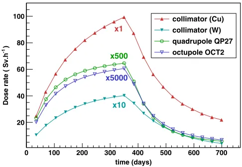
1W=m in the magnets and 20 kW at the collimator for a maximum beam current of 62.5 mA and a minimum beam current of 6.25 mA. The induced activity inside the quadrupoles after this period is shown in Fig.9, inside the octupoles in Fig.10, and inside the collimator is shown in Fig. 11. As expected, the worst affected beam line component is the collimator in front of the target monolith. There is a factor of approximately 100 difference in the total induced activity inside the quadrupoles, octupoles, and collimator.
The results so far have shown the activity after 365 days of exposure and 30 days of cooling off. However, Eq.(10)
can be used to calculate the activity at any time t, both during the beam exposure timet1for which t¼t1, as well
[image:9.612.52.561.75.298.2]as during the cooling-off period. The activity inside the accelerator components was calculated at various intervals during the 365 days of beam exposure and after the accelerator shut down. For each beam line element the total amount of Bq for each isotope was converted using
TABLE II. List of radioactive isotopes produced inside the magnets and collimators by spallation reactions that contribute to the induced activity. The dose rates at 1 m are per Bq of the active isotope considering a point source.
Isotope (fSvh−1Bq−1) Half-life Isotope (fSvh−1Bq−1) Half-life Isotope (fSv h−1Bq−1) Half-life
241Am 84.79 432 y 137Cs 103.2 30.2 y 124Sb 288.3 60.2 d
243Am 84.56 7388 y 152Eu 201.2 13.5 y 125Sb 102.8 2.7 y
198Au 78.82 2.7 d 154Eu 204.2 8.6 y 46Sc 315.5 83.7 d
199Au 18.66 3.1 d 59Fe 178.9 44.5 d 75Se 232.3 119.7 d
133Ba 123.1 10.5 y 153Gd 46.59 240.4 d 113Sn 48.44 115 d
7Be 9.292 532 d 172Hf 33.57 1.87 y 125Sn 46.74 9.64 d
207Bi 360.3 32.9 y 203Hg 68.41 46.6 d 85Sr 205.2 64.85 d
109Cd 49.83 1.2 y 125I 74.32 59.4 182Ta 208.6 114.4 d
139Ce 55.54 137.6 d 111In 135.6 2.8 d 160Tb 178.8 72.3 d
141Ce 19.79 32.5 d 192Ir 159.9 73.8 d 161Tb 18 6.9 d
144Ce 6.30 285 d 54Mn 138.2 312 d 44Ti 39.09 60.2 y
56Co 520.5 77.2 d 94Nb 264.8 2.03E4 y 170Tm 1.673 128.6 d
57Co 40.87 271.7 d 95Nb 129.8 35 d 88Y 481.9 106.65 d
58Co 165.9 70.8 d 239Np 138.6 2.35 d 169Yb 88.37 32 d
60Co 370.3 5.3 y 185Os 131 93.6 d 65Zn 89.24 244 d
51Cr 6.32 27.7 d 210Pb 68.01 22.3 y 95Zr 125.8 64 d
132Cs 155.6 6.5 d 84Rb 232.6 32.7 d
131373 683768 4.64339e+07 6.64268e+08 1.10996e+09 5.61087e+07 8.4372e+07 2.93861e+08 3.8278e+07 2.30217e+08 1.50828e+07
Be7 Sc46 Ti44 Cr51 Mn54 Fe59 Co56 Co57 Co58 Co60 Zn65
Activity (Bq) 3 10 4 10 5 10 6 10 7 10 8 10 9 10 10 10 11 10 12 10 13 10 14 10 quadrupole QP20
Total activity = 2.53939e+09 Bq = 365 days BEAM ON
t
= 30 days
BEAM OFF t 131373 683768 4.86339e+07 5.56912e+08 1.56176e+09 5.61098e+07 8.27182e+07 2.93861e+08 3.82102e+07 2.30217e+08 1.50828e+07
Be7 Sc46 Ti44 Cr51 Mn54 Fe59 Co56 Co57 Co58 Co60 Zn65
Activity (Bq) 3 10 4 10 5 10 6 10 7 10 8 10 9 10 10 10 11 10 12 10 13 10 14 10 quadrupole QP21
Total activity = 2.88432e+09 Bq
= 365 days
BEAM ON
t
= 30 days
BEAM OFF t 131373 683768 5.07306e+07 6.64268e+08 1.36813e+09 5.61108e+07 8.1088e+07 2.93861e+08 3.81425e+07 3.52656e+08 1.50828e+07
Be7 Sc46 Ti44 Cr51 Mn54 Fe59 Co56 Co57 Co58 Co60 Zn65
Activity (Bq) 3 10 4 10 5 10 6 10 7 10 8 10 9 10 10 10 11 10 12 10 13 10 14
10 quadrupole QP22
Total activity = 2.92088e+09 Bq tBEAM ON = 365 days = 30 days
BEAM OFF t 131373 683768 5.27293e+07 7.17946e+08 1.69085e+09
1.32076e+08 7.94876e+07 2.93861e+08
5.07633e+07
2.30217e+08
1.50828e+07
Be7 Sc46 Ti44 Cr51 Mn54 Fe59 Co56 Co57 Co58 Co60 Zn65
Activity (Bq) 3 10 4 10 5 10 6 10 7 10 8 10 9 10 10 10 11 10 12 10 13 10 14
10 quadrupole QP23
Total activity = 3.26382e+09 Bq = 365 days BEAM ON
t
= 30 days
BEAM OFF t 131373 683768 5.46354e+07 6.64268e+08 1.56176e+09 5.61128e+07 7.79212e+07 2.93861e+08 3.80079e+07 5.36314e+08 1.50828e+07
Be7 Sc46 Ti44 Cr51 Mn54 Fe59 Co56 Co57 Co58 Co60 Zn65
Activity (Bq) 3 10 4 10 5 10 6 10 7 10 8 10 9 10 10 10 11 10 12 10 13 10 14
10 quadrupole QP24
Total activity = 3.29878e+09 Bq = 365 days BEAM ON t
= 30 days BEAM OFF t 131373 683768 5.64538e+07 7.17946e+08 2.52991e+09
1.3208e+08 1.97018e+08 2.93861e+08
5.05845e+07
5.97533e+08
1.50828e+07
Be7 Sc46 Ti44 Cr51 Mn54 Fe59 Co56 Co57 Co58 Co60 Zn65
Be7 Sc46 Ti44 Cr51 Mn54 Fe59 Co56 Co57 Co58 Co60 Zn65
Activity (Bq) 3 10 4 10 5 10 6 10 7 10 8 10 9 10 10 10 11 10 12 10 13 10 14
10 Total activity = 4.59128e+09 Bq quadrupole QP25
= 365 days BEAM ON t
= 30 days BEAM OFF t 131373 683768 1.05613e+08 9.86335e+08 3.88531e+09 2.84019e+08 7.49013e+07 5.1853e+08 5.04956e+07 7.81191e+08 1.50828e+07
Be7 Sc46 Ti44 Cr51 Mn54 Fe59 Co56 Co57 Co58 Co60 Zn65
Activity (Bq) 3 10 4 10 5 10 6 10 7 10 8 10 9 10 10 10 11 10 12 10 13 10 14
10 quadrupole QP26
Total activity = 6.70229e+09 Bq tBEAM ON = 365 days = 30 days
BEAM OFF t 131373 1.81349e+06 1.08622e+08 1.02189e+10 4.00294e+10 1.95535e+09 3.63405e+08 3.58901e+09 5.92169e+08 9.59678e+09 1.50828e+07 Activity (Bq) 3 10 4 10 5 10 6 10 7 10 8 10 9 10 10 10 11 10 12 10 13 10 14 10 15
10 Total activity = 6.64707e+10 Bq quadrupole QP27
= 365 days BEAM ON t
[image:10.612.103.508.42.660.2]= 30 days BEAM OFF t (a) (b) (c) (d) (e) (f) (g) (h)
time (days)
0 100 200 300 400 500 600 700
)
-1
Dose rate ( Sv.h
0 0.02 0.04 0.06 0.08 0.1 0.12 0.14
quadrupole QP27 quadrupole QP26 quadrupole QP25 quadrupole QP24 quadrupole QP23 x1
x8
x10
x10
x10
time (days)
0 100 200 300 400 500 600 700
)
-1
Dose rate ( Sv.h
0.002 0.004 0.006 0.008 0.01
0.012 octupole OCT2
octupole OCT1
[image:11.612.68.541.46.217.2](a) (b)
FIG. 12. Dose rates calculated at 1 m from the element surface for the HEBT-S3 magnets: (a) quadrupoles and (b) octupoles.
2.01126e+09
8.94773e+09
8.29815e+11
4.21913e+12 3.85336e+12 2.67953e+12 2.66354e+12
2.17162e+13
3.08102e+12
2.68612e+13
9.97258e+11
Be7 Sc46 Ti44 Cr51 Mn54 Fe59 Co56 Co57 Co58 Co60 Zn65 Se75 Rb84 Sr85 Y88 Zr95 Nb94 Nb95
Ru106 Cd109 In111 Sn113 Sn125 Sb124 Sb125 I125 Cs132 Cs134 Cs137 Ba133 Ce139 Ce141 Ce144 Eu152 Eu154 Gd153 Tb160 Tb161 Tm170 Yb169 Hf172 Ta182 Os185 Ir192 Au198 Au199 Hg203 Pb210 Bi207 Th228 Np239 Am241 Am243
Activity (Bq)
4 10
5 10
6 10
7 10
8 10
9 10
10 10
11 10
12 10
13 10
14 10
15 10
16 10
17 10
Total activity (Cu) = 6.6912e+13 Bq
= 365 days BEAM ON
t
= 30 days BEAM OFF
t
1.94234e+07
9.49924e+06
4.73121e+08
1.65041e+09
7.55212e+08
2.09721e+08 2.12964e+08
1.36563e+09
1.70715e+08 3.31803e+08 1.72318e+09 1.00556e+09
5.0614e+08
2.81195e+09
1.4525e+09
2591.58
5.05115e+08 2.67936e+08
3.90012e+07 3.07659e+07
4.13133e+10
1.73908e+10
1.8251e+06
6.32368e+07 1.03634e+08 5.65785e+08 3.25986e+08
1.66678e+06
5.3682e+09
6.26405e+08
5.01178e+07
260183
5.94389e+07 6.4059e+07
4.02263e+09
5.7336e+06
5.55397e+07
5.63113e+09
3.06506e+10
6.78776e+11 1.90067e+12
9.76342e+08
[image:11.612.131.484.265.457.2]Total activity (W) = 2.70027e+12 Bq
FIG. 11. Total induced activity inside the HEBT-S3 collimator. Isotopes produced in the copper yield of the collimator are shown in red, isotopes produced in the tungsten coating of the collimator are shown in green.
227644
1.1695e+06
1.01716e+08
1.03132e+09 2.3612e+09
2.63919e+08
1.26994e+08
5.13663e+08
6.63678e+07
5.31e+08
2.59559e+07
Be7 Sc46 Ti44 Cr51 Mn54 Fe59 Co56 Co57 Co58 Co60 Zn65 Se75
Activity (Bq)
3
10
4
10
5
10
6
10
7
10
8
10
9
10
10
10
11
10
12
10
13
10
14
10
Activity (Bq)
3
10
4
10
5
10
6
10
7
10
8
10
9
10
10
10
11
10
12
10
13
10
14
10
Activity inside octupole OCT1
Total activity = 5.02354e+09 Bq
= 365 days
BEAM ON
t
= 30 days
BEAM OFF
t
227644
1.1695e+06
1.01716e+08
1.35339e+09 2.94209e+09
3.39889e+08
1.26994e+08
6.63442e+08
6.63678e+07
7.14658e+08
2.59559e+07
Be7 Sc46 Ti44 Cr51 Mn54 Fe59 Co56 Co57 Co58 Co60 Zn65
Activity inside octupole OCT2
Total activity = 6.3359e+09 BqtBEAM ON = 365 days
= 30 days
BEAM OFF
t
[image:11.612.59.558.511.696.2](a) (b)
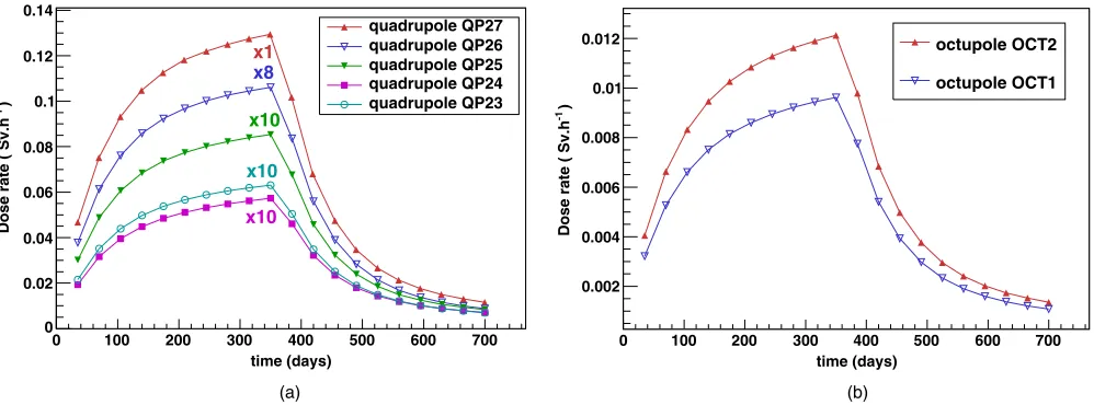
the Bq-to-dose conversion factors into dose (Table II). Since these conversion factors are for point sources, they do not account for self-absorption of the materials. Then the individual doses contributions from various isotopes were added up into a final result. The results are shown in Fig.12
for various magnets and in Fig. 13 for the elements that are closest to the spallation target. The curves for different elements have been scaled for a direct and better compari-son. The generic curves can obviously be divided into two separate parts corresponding to activation (data points before the end of irradiation) and decay (data points after the end of irradiation).
V. CONCLUSION
The primary concern in building high-power accelerators is to minimize the beam losses because they produce first damage to the whole accelerator system due to the high beam energy deposition, and second they produce induced radioactivity. Predictions of the residual activity in the accelerator components is important for allowing access of maintenance personal after the beam is turned off. In this paper we presented a generic study of induced activation in accelerator components, and the same methodology can be applied to any future study of element activation from other accelerator facilities around the world. In this study we discussed the methodology of estimating the induced radioactivity in magnets and collimators of the ESS HEBT-S3 beam line method, which relies on the computation of the production rate of each isotope of interest. All possible factors have been considered: the direct interaction of the proton beam with the elements, the interaction of the backscattered neutrons from the target, and the isotope production as a result of the decay of other isotopes produced in these interactions. The main factor proved to be the backscattered neutrons, the particle collimator placed in front of the target being the worst affected. The induced activity was calculated both during and after a
365-day beam exposure, reaching a maximum of100Sv=h for this particular beam element.
[1] “Council Directive 96/29/EURATOM laying down basic safety standards for the protection of the health of workers and the general public against the dangers arising from ionizing radiation,”The Council of the European Union, 1996.
[2] S. F. Mobbs and M. P. Harvey,Exempt Concentrations and Quantities for Radionuclides Not Included in the European Basic Safety Standards Directive, Report No. NRPB-R306 (Chilton National Radiological Protection Board, Chilton, Didcot, Oxfordshire, UK, 1999.
[3] A. H. Sullivan, A Guide to Radiation and Radioactivity
Levels Near High Energy Particle Accelerators(Nuclear
Technology Publishing, Ashford, 1992).
[4] GEANT4—A toolkit for particle passage through matter, version geant4.9.5.p01,http://geant4.web.cern.ch/geant4//. [5] A. Heikkinen, P Kaitaniemi, and A Boudard,J. Phys. Conf.
Ser.119, 032024 (2008).
[6] IAEA benchmark for spallation reactions,http://www‑nds .iaea.org/spallations/.
[7] A. Howard et al., in 1st Workshop on Accelerator
Radiation Induced Activation (Paul Scherrer Institute,
Switzerland, 2008).
[8] M. B. Chadwicket al.,Nucl. Data Sheets112, 2887 (2011). [9] T. Nakagawaet al.,J. Nucl. Sci. Technol.32, 1259 (1995). [10] Yu. N. Shubinet al., International Atomic Energy Agency
Report No. INDC(CCP)-385, 1995.
[11] J. P. Wellisch,Nucl. Instrum. Methods Phys. Res., Sect. A 502, 669 (2003).
[12] S. Garny, G. Leuthold, V. Mares, H. G. Paretzke, W. Ruhm,
IEEE Trans. Nucl. Sci.,56, 2392 (2009).
[13] R. MacFarlane, New Thermal Neutron Scattering Files for ENDF/B-VI, Release 2, Los Alamos Laboratory Technical Report, 1994.
[14] S. Peggs et al., European Spallation Source, Conceptual Design Report No. ESS-2012-001, Lund, Sweden, 2012. [15] A. I. S. Holm, S. P. Møller, and H. D. Thomsen, in Pro-ceedings of the 3rd International Particle Accelerator
Conference, New Orleans, LA, 2012(IEEE, Piscataway,
NJ, 2012), MOPPD049.
[16] A. I. S. Holm, S. P. Møller, and H. D. Thomsen, in Pro-ceedings of the 2nd International Particle Accelerator
Conference, IPAC-2011, San Sebastián, Spain(EPS-AG,
Spain, 2011), THPS050.
[17] N. V. Mokhov and W. Chou, in The 7th ICFA
Mini-Workshop on High Intensity, High Brightness Hadron
Beams, Wisconsin, 1999, Fermilab-Conf-00/185 (Fermi
National Accelerator Laboratory, Batavia, IL, 2000). [18] R. Miyamoto, B. Cheymol, H. Danared, M. Eshraqi,
A. Ponton, J. Stovall, and L. Tchelidze, in Proceedings of HB2012, Beijing, China, 2012, The 52nd ICFA ad-vanced Beam Dynamics Workshop on High Intensity and High Brightness Hadron Beams, WEO3A02.
[19] D. S. Smith and M. G. Stabin, Health Phys. 102, 271 (2012).
time (days)
0 100 200 300 400 500 600 700
)
-1
Dose rate ( Sv.h
20 40 60 80
100 collimator (Cu)
collimator (W)
quadrupole QP27
octupole OCT2
x1
x500
x5000
[image:12.612.53.296.44.212.2]x10