2017 2nd International Conference on Artificial Intelligence and Engineering Applications (AIEA 2017)
ISBN: 978-1-60595-485-1
A Novel Recognition and Repair Method of
Abnormal Data of Current Transformer
JIAWEI XING, NENG JIN, ZHONGRUI ZHANG, XIANGNING LIN and QINGGE JIANG
ABSTRACT
The abnormal sampling information of transformer will lead to maloperation of substation protection system. To solve this problem, an abnormal data recognition algorithm based on the waveform similarity is proposed in this paper, and the abnormal data is repaired by interpolation or replacing with substation area redundancy information, thus maloperation of protection system is avoided. The scheme can recognize the abnormal data accurately and quickly, and the abnormal data repair scheme will not reduce the operation time of the original protection. The feasibility of the scheme is verified by theoretical analysis and simulation results.
KEYWORDS
Transformer, abnormal data, maloperation, waveform similarity, substation area information.
INTRODUCTION
As the source of information collection of power grid protection and control system, current transformer plays an important role. However, both the traditional electromagnetic transformer and the new electronic transformer are faced with the problem of signal interference form the external environment and the instability of the devices, which will lead to maloperation of protection [1, 2]. The protection maloperation caused by abnormal sampling data occurs occasionally [3], to solve this problem, sampling data should be judged abnormal or not and repaired when necessary in the secondary equipment.
_________________________________________
Jiawei Xing, Xiangning Lin, State Key Laboratory of Advanced Electromagnetic Engineering and Technology (Huazhong University of Science and Technology), Wuhan 430074, China.
Corresponding Author: Neng Jin, State Key Laboratory of Advanced Electromagnetic Engineering and Technology (Huazhong University of Science and Technology), Wuhan 430074, China. [email protected].
Zhongrui Zhang, Electric Engineering & Renewable Energy School, China Three Gorges University, Yichang 443002, China;
500kV/220kV
L1
F1
I5
L2
L3
I3
I2
I4
I1
Bus1
CT2
Substation A
[image:2.612.180.418.53.167.2]Substation B
Figure 1. Diagram of substation and lines.
Many related researches have been done. According to the characteristics for the abnormal data of electronic current transformer, [4] proposes an abnormal data resisting method based on sampling data amplitude comparison. [5] Judges whether the sampled data is abnormal by effectively determine the continuous three sampling point. In addition, other method that uses the symmetry of the positive and negative half-wave of the current, which is similar to the method of judging inrush current. However, the above methods have the problem that the threshold of criterion is hard to set, the operation of protection may slow down, and the error setting can even lead to protection refusal.
To solve these problems, an abnormal data recognition algorithm based on the waveform similarity is proposed in this paper, and the abnormal data is repaired by interpolation or replacing with substation area redundancy information, thus maloperation of protection system is avoided.
ABNORMAL DATA RECOGNITION AND REPAIR SCHEME BASED ON THE WAVEFORM SIMILARITY
Basic Principle of Substation area information redundancy.
The diagram of substation and lines is as shown in Fig. 1, when Bus1 is in normal operation, the current relationship between the incoming line and outgoing line of the bus is shown in (1).
I1=I2+I3+I4 (1)
Once one of the related transformers is interfered and the sampling data is abnormal, the relationship is broken, as shown in (2).
I1≠I2+I3+I4 (2)
checked in substation A and B respectively. The checkout of current I2 in substation A is analyzed in section 2.2, the checkout of current I5 in substation B is the same and omitted.
2.2 Abnormal Data Recognition and Repair Scheme.
The definition of waveform similarity is S=NH Hset N
in this paper, N represents
the number of sampling data in one period, H represents the Euclidean distance between two sampling data of line current and redundancy current at the same time, the similar threshold is set as Hset=1.2 *In , In represents the rated current,
set
H H
N represents the total number of sampling data where H is smaller than Hset in
this period. S should be calculated at the period when differential protection starts. Considering different line protection start situations, the protection scheme is analyzed in details.
(1) For the case that the transient interference results in abnormal sampling data and external fault, thus leading to the maloperation of line differential protection. Because the transient interference attenuates quickly in general, the ratio of abnormal sampling data in one cycle is relatively low, generally less than 10% (equivalent to no more than 2 abnormal points for 20 sampling points in one cycle), thenS 90%. If the number of abnormal sampling data is small, the interpolation
algorithm can be used to repair the abnormal data, and the accuracy is higher; (2) For the case of long duration of interference or transformer saturation, the number of abnormal sampling data is big, based on the characteristics of long duration of interference or transformer saturation, assuming 30% S 90% at this
time. Then greater error will be brought if the traditional interpolation algorithm is used to repair the abnormal data, it. In this case, based on the substation area information sharing, the redundant current is used to replace the line current, and the accuracy is higher;
(3) For the case that a fault occurs on the line, if the transformer is not saturated at this time, theoreticallyS100%. There is no need to repair the sampling data; in case of transformer saturation caused by serious fault, the waveform similarity is between (30%, 90%), then the redundant current is used to replace the line current, then calculate the differential protection criterion again and the differential protection can still operate.
[image:3.612.84.508.630.686.2](4) For the case that a fault occurs on the bus, then the waveform similarity between redundant current and line current is low, even for slight fault, the waveform similarity is less than 30%. Thus, it is to be judged that a fault occurs on the bus if S30% and line differential protection is blocked.
TABLE 1. LINE CURRENT REDUNDANCY OF SUBSTATION A.
Line Current Redundancy Current
I2 I1-I3-I4
I3 I1-I2-I3
CASE STUDY
According to Fig. 1, a simulation model is built in PSCAD with 220kV voltage classes, the line parameters are as follows: r1=0.012Ω/km, x1=0.1045Ω/km, c1=0.01272uF/km, r0=0.0948Ω/km, x0=0.2894Ω/km, c0=0.009uF/km, L1=60km, L2=20km, L3=30km. The differential protection of bus and line uses current phasor information extracted by Full Cycle Fourier algorithm, the sampling rate is 1000Hz, thus there is 20 sampling data in one period. A single-phase-to-ground fault occurs at F1 at 0.23s. Several simulation scenarios have been discussed below. 20 sampling datas from point 231 to 250 is analyzed.
Single Sampling Data of Current I2 is Abnormal.
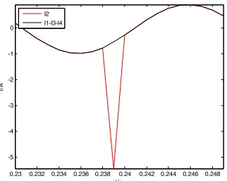
10 times interference is set in sampling point 240, which isI2(240) 10 * (240)= I2 . Thus before and after the interference, I2(240)=- 0. 5432A and I2(240) 5.432A respectively. Simulation shows that the differential current and braking current of line L1 and Bus1 is 1.4162A/1.1987A and 1.4169A/1.8224A respectively. Then the differential protection of line L1 operate incorrectly and the differential protection of Bus1 doesn’t operate. Fig. 2 shows the waveform of redundancy current I1-I3-I4 and line current I2, it can be seen from Fig. 2 that S95%, Lagrange interpolation
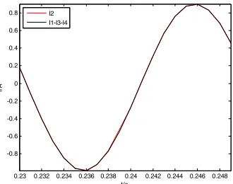
algorithm is used to repair the abnormal data, which is I(2240) 0.519 after repairing. The differential current and braking current of line L1 and Bus1 is 0.0041A/0.9460A and 0.0049A/1.5697A respectively after repairing, the differential protection of line L1 will operate and Bus1 will not operate. Fig. 3 shows the waveform of redundancy current I1-I3-I4 and line current I2 after repairing, it can be seen thatS100%.
0.23 0.232 0.234 0.236 0.238 0.24 0.242 0.244 0.246 0.248 -5
-4 -3 -2 -1 0
t/s
I/
A
[image:4.612.216.377.437.565.2]I2 I1-I3-I4
0.23 0.232 0.234 0.236 0.238 0.24 0.242 0.244 0.246 0.248 -0.8
-0.6 -0.4 -0.2 0 0.2 0.4 0.6 0.8
t/s
I/A
[image:5.612.212.377.62.192.2]I2 I1-I3-I4
Figure 3. Waveform of redundancy current I1-I3-I4 and line current I2 after repair.
0.23 0.232 0.234 0.236 0.238 0.24 0.242 0.244 0.246 0.248 -4
-2 0 2 4 6
t/s
I/
A
I2 I1-I3-I4
Figure 4. Waveform of redundancy current I1-I3-I4 and line current I2.
Several Sampling Data of Current I2 is Abnormal.
Ten times the sampling value of point 240~245,
That isI2 240~245( )10* 2 240~245I( ). Then the differential current and braking
current of line L1 and Bus1 is 3.1613A/2.1355A and 3.1621A/2.7592A respectively, then the differential protection of line L1 and Bus1 operate incorrectly. Fig. 4 shows the waveform of redundancy current I1-I3-I4 and line current I2, it can be seen from Fig. 4 that S75%, then interpolation algorithm will
cause big error if used. Thus I2 is replaced by redundancy current I1-I3-I4. Then the differential protection of line L1 and Bus1 doesn’t operate after repairing.
SUMMARY
ACKNOWLEDGEMENTS
This work is supported by National Natural Science Foundation of China (No. 51577077) and the Science and Technology Project of State Grid Corporation of China (SGTYHT/16-JS-198).
Corresponding Author: Neng Jin, State Key Laboratory of. Advanced Electromagnetic Engineering and Technology (Huazhong University of Science and Technology), Wuhan 430074, China. [email protected].
REFERENCES
1. Hengtian Wu, Chongqing Jiao, Xiang Cui, et al. Transient Electromagnetic Disturbance Induced on the Ports of Intelligent Component of Electronic Instrument Transformer Due to Switching Operation in 500kV GIS Substations. IEEE Access. Vol. 5 (2017), p. 5104-5112.
2. Zhihong Xiao, Shenwang Li, Zhihong Guo, et al. Analysis of the Functional Mechanism of the Interference Magnetic Field on Straight Light Path Type Optical Current Transformers. 2016 Sixth International Conference on Instrumentation and Measurement, Computer, Communication and Control. China, 2016 July, p. 434-438.
3. Chi Zhang, Zaibin Jiao, Xiaoning Kang, et al. Countermeasures on Abnormal Data in the Signal Acquisition System of Digital Substations. 2016 IEEE PES Asia-Pacific Power and Energy Engineering Conference (APPEEC). China, 2016, Oct, p. 2037-2040.
4. Liang Zhao, Yuchun Qian, Hongjun Liu, et al. Abnormal Data Resisting Method in Digital Substation. Automation of Electric Power Systems. Vol. 34 (2010) No. 19, p. 97-99.