2016 International Conference on Manufacturing Science and Information Engineering (ICMSIE 2016) ISBN: 978-1-60595-325-0
A Knowledge-based Parametric Design System
for Trimming Dies
YUNPENG HAO and YILIN WANG
ABSTRACT
In this paper, by analyzing the structure characteristics of trimming dies, and combining with the theory of knowledge engineering, the author expounds the system architecture of the knowledge-based parametric design system and the design methods and key points of its main modules design. At present, this system has been put into practice and has achieved good benefits.1
INTRODUCTION
Trimming die design is difficult because of the sophisticated surface of the panel, the high quality demand, the complicated modelling. Traditional methods are not conducive to raising efficiency and lowering costs. Therefore, it’s really necessary to develop a die design system to increase efficiency. During the recent decade, more and more investigators are shifting their attention to the development of die design system. For example, Bor-Tsuen Lin, et al. [1] developed an automated design system for drawing dies to output designs of the main components of these dies. Zhixia Zhang, et al. [2] developed a design system for trimming dies based on the parametric die template, which can be used to do some parametric design. But there is still so much research space remained in this field.
Based on structural features of trimming dies, this paper takes a knowledge-based engineering way to develop the trimming dies design system on the platform of NX system. The research was carried out in the following aspects: (1) automatic modelling of die structure according to features of trimming dies; (2) implementing the parametric design of working components and standard parts; (3) introducing knowledge-based engineering into systematic modeling design. This design is proved to have reduced labor intensity and increased efficiency.
SYSTEM STRUCTURE
Features of Trimming Dies
Trimming dies have complicated structures. It has multiple components many of which are standard and typical parts. This increases the similarity of the trimming dies design and frequency of using standard and typical parts. Therefore, it’s necessary to look into the typical structures to divide the design system into parts with high cohesion and low coupling before developing the design system.
Systematic Framework
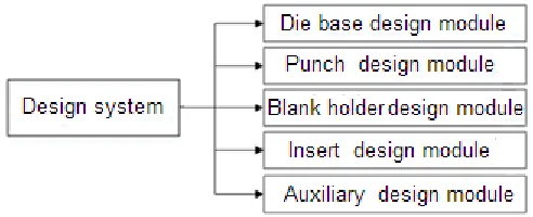
Traditional methods fail to tap into the full potential of the modeling features of trimming dies. They include too much replicated work which holds back the design efficiency and cost effectiveness. To achieve quick and effective design, the author has analyzed different typical structures of trimming dies and developed this design system. In accordance with the features of components and software engineering, the author divides the system to sub-models of the design of die bases, punches and blank holders, inserts design and other auxiliary functions (as is shown in Figure 1). When using the system, designers are able to choose structures and parameters timely and accurately that helps with the design of components of trimming dies. The system is proved to be effective in designing models and reduce the cost.
Main Modules Design
DIE BASE DESIGN MODULE
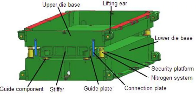
[image:2.612.174.420.501.601.2]The structure of trimming dies varies from die to die, but the styles of die bases tend to be similar. The typical structure of die base is shown in Figure 2. In this paper,
Figure 1. Structure of trimming die design system.
solve the above problems, this system provides multiple interfaces through which engineers can select the specific brand or specification of standard parts. And this system can automatically generate all the components correctly.
[image:3.612.128.467.316.481.2]After analyzing the structure of trimming dies, it’s easy to find that the termination of dies is consist of guide components, the nitrogen system, lifting devices, the security platform and devices for the transportation [3]. Except that, clamp plates are also necessary to join the front termination and the back one together. All of the components have their own design specifications. Because of the low coupling between these components, it’s easy for designers to create models independently. Almost all of the die bases are composed of these components. Accordingly, modularization technology is introduced into this system. With the help of the advanced technology, the die base design module can be divided into a few parts (as is shown in Figure 3). On this basis, developing a satisfactory design system is not far away. And the stratification and reliability are also lightly to be guaranteed. The functional architecture diagram is designed as follows.
Figure 2. Structure of die base.
PUNCH DESIGN MODULE
According to the results of the new research in a die technology company, in actual production, punch design includes two parts, assembly-level design and part-level design. The assembly-level design, also called structure of punch, are used to design the main body, trimming edges, non-standard holes, open areas on molding surface and stiffeners. The part-level design, also named standard parts design, are applied to add sunk keys, recumbent keys, screws, pins, lifting devices and so on. Combined with the characteristics of punch main body, each of the module parts can be developed as an independent function unit. The functional architecture diagram of punch design module is shown in Figure 4.
BLANK HOLDER DESIGN MODULE
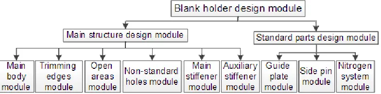
[image:4.612.99.495.366.461.2]Quite similar to the punch design module, the blank holder design module also includes the modules to design the main body, trimming edges, non-standard holes, open areas on molding surface and stiffeners. But the standard parts design module is different from that of the punch design module. The functional architecture diagram of blank holder design module is shown in Figure 5.
Figure 4. The functional architecture diagram of punch design module.
[image:4.612.103.495.509.606.2]DIE DESIGN MODULE
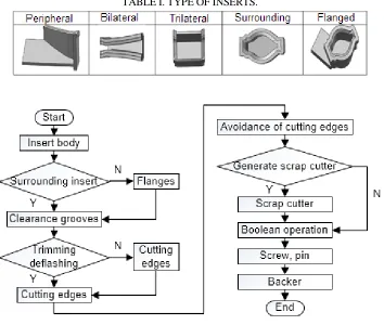
Some parts of punch are prone to be worn out. So, these parts may be designed as inserts that are easy to be changed. According to the shape and position of trimming line and the necessity of flange, inserts can be classified into five types, peripheral inserts, bilateral inserts, trilateral inserts, surrounding inserts and flanged inserts (as is shown in Table I). But the structure of different types tends to be similar. The insert body, cutting edges, flanges (not necessary), clearance groove, avoidance of cutting edges and scrap cutters. Taking into account the characteristics of typical inserts, the author sums up the design process (as is shown in Figure 6).
KEY TECHNOLOGY
Parametric Design
Parametric design technology is one of the main technologies in CAD molding field. Through analyses of the structure of dies, the design usually extracts several key
[image:5.612.122.476.352.652.2]TABLE I. TYPE OF INSERTS.
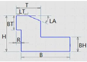
Figure 7. Key parameters of insert.
parameters in the process of modeling, and then make the other parameters associated with them [4]. And next, the designers can control the shape of die through changing key parameters. For example, in inserts design module, combined with the experience of veteran designers, the author summarized some key parameters (as is shown in Figure 7). In this figure, “H” represents for height of insert, “T” for thickness of the insert, “BT” for height of cutting edges, “LT” for thickness of cutting edges, “R” for width of avoidance, “B” for thickness of flanges, and “BT” for height of flanges. The designers can input the value of key parameters they need to control the insert created by the design module.
Knowledge Based Engineering
Knowledge-based engineering (abbreviated KBE) technology is a kind of principle and method of artificial intelligence. It works by combining artificial intelligence with CAD technology. Designers should create many product/project global knowledge models, which contains inheritance, encapsulation and extensibility. It stores and expresses the relevant geometric and non-geometric information as well as the rules and experiences of design, analysis and engineering. The system obtains the optimal solution of product design and engineering problems by optimizing design strategy and intelligent decision method. Knowledge-based engineering mainly includes four aspects: knowledge acquisition, knowledge representation, knowledge inference, and knowledge management [5]. Trimming dies have complex structure, and various in parts. The design of the source of knowledge is also more extensive. So we need to make a systematic classification of this knowledge.
EXAMPLES FOR DESIGN
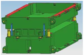
Figure 8. An instance of die base design. Figure 9. An instance of punch design.
Figure 10. An instance of blank holder design. Figure 11. An instance of insert design.
CONCLUSION
The thesis combines the parametric design methods and knowledge-based engineering theory, and explored the keys for developing the design system of trimming dies. It also focuses on the design for dies, pressure plates and insertion. However, the complicated structure and high demanding nonstandard cover make it difficult to enhance the generalization, standardization and intellectualization of developing the design system and it remains the key for the mass application for automakers.
REFERENCES
1. B. T. Lin, S. H. Hsu. 2008. Automated design system for drawing dies. Expert Systems with
Applications, 34(3): 1586-1598.
2. Z. X. Zhang, Z. B. Zhang, Y. Q. Liu, et al. 2014. Template-Based Interactive Die Design System
of Automobile Panel. Journal of Netshape Forming Engineering, 6(6): 127-132.
3. Y. L. Wang, G. Y. Wang. 2014. Study on Modular Design of Trimming Die Structure for
Automotive Panels. Advanced Materials Research, 945: 73-76.
4. Y. L. Wang, X. G. Hu. 2011. Research on Template-Based Parameterized Structure Design for
Drawing Dies. Digital Manufacturing and Automation (ICDMA), 2011 Second International Conference on. IEEE, pp. 1022-1025.
5. J. Q. Zheng, Y. L. Wang, Z. G. Li. 2007. KBE-based stamping process paths generated for