University of Huddersfield Repository
Opoz, Tahsin Tecelli and Chen, Xun
Finite element simulation of grinding process and microscale abrasive wear.
Original Citation
Opoz, Tahsin Tecelli and Chen, Xun (2009) Finite element simulation of grinding process and
microscale abrasive wear. In: Proceedings of Computing and Engineering Annual Researchers'
Conference 2009: CEARC’09. University of Huddersfield, Huddersfield, pp. 165171. ISBN
9781862180857
This version is available at http://eprints.hud.ac.uk/id/eprint/6887/
The University Repository is a digital collection of the research output of the
University, available on Open Access. Copyright and Moral Rights for the items
on this site are retained by the individual author and/or other copyright owners.
Users may access full items free of charge; copies of full text items generally
can be reproduced, displayed or performed and given to third parties in any
format or medium for personal research or study, educational or notforprofit
purposes without prior permission or charge, provided:
•
The authors, title and full bibliographic details is credited in any copy;
•
A hyperlink and/or URL is included for the original metadata page; and
•
The content is not changed in any way.
For more information, including our policy and submission procedure, please
contact the Repository Team at: [email protected].
FINITE ELEMENT SIMULATION OF GRINDING PROCESS AND
MICRO-SCALE ABRASIVE WEAR
T.T. Opoz, X. Chen
University of Huddersfield, Queensgate, Huddersfield HD1 3DH, UK
ABSTRACT
This paper presents a review of grinding and polishing process in terms of mechanical interaction between process elements. The abrasive processing includes bonded and unbounded abrasive machining can be analysed as a two-body or three-body processing. Finite element simulations from previous works, each with a different simulation approach, covers the analyses in respect of thermal behaviour of grinding, and single grain simulation. Moreover, microscale abrasive material removal in two-body and three-body abrasive process is addressed based upon previously investigation of microscale abrasion tests.
Keywords finite element method; grinding; abrasive wear; two-body abrasion; three-body abrasion
1
INTRODUCTION
Grinding is a complex material removal process due to the large number of abrasive grains with unknown geometry varying with time (Aurich et al (2009)). Another abrasive process, polishing, presents more complex material removal mechanism than grinding because of its extra motions of abrasives. In order to gain insight into the complexity of material removal in these processes, many investigations have been carried out by researchers in the universities and industries. Process models of abrasive processing are often used to describe the complex relationships between machining parameters and processing behaviours that lead to different work results. The interaction between active abrasives and workpiece is analysed to predict grinding forces, temperature, grinding energy consumption, surface integrity etc.. Various approaches for building up a process model, both physical and empirical, were summarised by Brinksmeier1 et al (2006) including fundamental analyses with kinematic model, finite element method (FEM), molecular dynamics, artificial neural nets, and rule based models. An extensive review of finite element modelling of grinding was done by Doman et al (2009). This provides a great insight of material behaviour in abrasive processing. On one hand process understanding was established through process modelling, so that knowledge about the process can be enhanced. On the other hand Simulation using suitable models makes it possible in the future to predict process behaviour and component quality. Both modelling and simulation will help engineers to determine optimum process parameters prior to the manufacturing process. Evans et al (2003) reviewed the material removal mechanism in lapping and polishing. They characterize polishing via the fundamental interactions between four critical elements of the process, namely the workpiece, fluid, granule and lap. Understanding the interactions between these four elements is critical for improving the process control ability so as to achieve higher productivity and better part quality. In such loose abrasive processing, abrasives are able to roll freely between workpiece and counterface or to penetrate into the counterface losing their freedom or rotation. These two types of abrasive motion, translation and rotation, result in different modes of material removal mechanisms. While in the case of freely-rolling abrasive processing, so-called three-body abrasion, material removal is caused by micro-fatigue and micro-cracking of the surface, the embedded abrasive processing, so-called two-body abrasion, leads to micro-ploughing or micro-cutting (Brinskmeier2 et al (2006)). The transition between three-body and two-body abrasive is a critical issue in processing quality control.
2
FINITE ELEMENT MODELS
date (Brinksmeier1 et al (2006)). Process parameters describing the grinding are shown in figure 1-(a). The input parameters for a typical FEA simulation are; geometry of the workpiece, properties of the workpiece material, grinding forces, process parameters, heat transfer coefficient between cooling lubricant and workpiece, cooling conditions and boundary conditions. A general macro-scale thermal model setup is shown in figure 1-(b). The macro-scale grinding FE models were sub-divided into four model types. Thermal (T) models can predict the temperature distribution within the workpiece whereas structural (S) models can determine the mechanical deformations and resulting stress. Thermal-structural (TS) models, or coupled models, can determine the resulting total stress from both thermal and mechanical loads. And Ceramic (C) models can be treated as a separate category from the thermal or structural analyses because of their fundamental difference in material removal mechanism. Each model is either two-dimensional (2D) or three-dimensional (3D) and uses an elastic (E), elastoplastic (P), or thermoplastic (TP) material model (Doman et al (2009)).
Chuang et al (2003) investigated grinding forces and the associated stress and deformation fields generated in a ceramic workpiece during plunge surface grinding. They designed a two- dimensional finite element model with the grinding parameters and the mechanical properties of the workpiece as input variables. Results show that the depth of subsurface shear failure zone increased with an increase in maximum undeformed chip thickness or the wheel depth of cut. The resulting local grinding force vector, maximum stress and damage zone sizes were predicted as a function of maximum undeformed chip thickness. Moulik et al. (2001) developed a Finite Element Model to calculate the temperatures and stresses arising due to a moving source heat. The grinding of elastic and elastic-plastic workpiece materials were simulated. The developed FE model was also applied to calculate the surface and sub-surface residual stress induced in an elastic-plastic solid by such sources of heat when convection heat transfer is assumed to occur at the solid surface. The finite element calculations showed that the near surface residual stresses produced by moving sources of heat are generally tensile.
In most macroscopic models the grinding wheel is represented as a combination of the heat source and the surface pressure, which is moved over the workpiece with feed speed. The exact distribution of the heat source within contact zone, between the workpiece and the grinding wheel, must be ascertained in order to provide realistic input parameters, in particular the heat flux distribution. Simplified profiles of the heat source were often idealized by assuming a rectangular, triangular, parabolic or trapezoidal shape. For the design of the simplified heat source it was essential to know the heat flux density which was passed from the heat source to the workpiece. Most of the temperature models were based on the theory by Carslaw and Jaeger (1959). This model was extended to take into account the cooling lubricant in front of and behind the contact zone of the workpiece and the constant temperature on clamped areas (ambient temperatures). The equation for the calculation of uniform heat flux density is shown in equation (1):
(1)
In addition to process parameters (e.g. cutting speed vc) and geometrical contact conditions (contact length lg, contact width of grinding wheel bk) the heat flux density depends on two factors of proportionality (energy dissipation Kv and heat distribution factor Kw) and the tangential force Ft during the process, the latter can be determined with a dynamometer. The factor Kv indicates the percentage of mechanical energy which is transformed into heat and can sometimes be set to Kv=1, because most grinding energy is transformed into heat (Brinksmeier1 et al (2006)).
Mamalis et al (2003) proposed a finite element model to simulate the precision and ultraprecision grinding of steel. The finite element model proposed is based on Jaeger’s model. It is a 2D model and the grinding wheel is considered to be a moving heat source. The heat sources is characterized by a physical quantity, the heat flux, q, that represents the heat entering an area of workpiece per unit time and is considered to be of the same density along its length which is taken equal to the geometrical contact length, , which is calculated from the relation
(2)
for the grinding of alloy steel workpieces with relatively low workpiece velocities. The resulting temperature profiles were used to predict the phase transformation and subsequent martensite depth
In contrast to macro-scale models, the microscopic simulation concept is based on the single grain scratch test. It is a multi-body system considering the single grain and the workpiece The micro-mechanical grinding theory was put forth in the works by Robert S. Hahn of the Heald Machine Company (Doman et al (2009)). Hahn (1962) proposed his rubbing hypothesis in 1962 where the material removal process by a single grain was accomplished in various stages, or phases. In his theory, illustrated schematically in figure 2, three distinct material removal phases exist as the grain is engaged into the workpiece by an amount and travels at a velocity vg. The rubbing or initial phase shown in figure 2(a) occurs at small depths resulting in local elastic deformation around the grain. At higher depths ( ), the ploughing phase is obtained which is obtained which is characterized by plastic upheaval of the material ahead of and to the side of the grain as illustrated in figure 2(b). This plastic surface deformation results in a groove, or scratch, but does not physically remove any material. Figure 2(c) depicts the final phase where material is finally removed in the form of a chip at even greater depths ( ). Lambropoulos et al (1996) developed an axisymmetric FE model of indentation on an elastic-perfectly plastic workpiece by a rigid indenter for the study of grinding optical glass. This model was used to investigate plastic zones created by abrasive contact. However, because no grain motion was used, no material removal could be modelled.
Klocke et al (2002) developed a 2D FE model that simulates single-grain scratch test where an abrasive grain was passed through the workpiece material. Using a coupled thermal structural (TS) analysis, temperature and stress fields were produced. The particular importance of this model is the way in which the workpiece is loaded. Rather than imposing heat flux and stresses, as done with the majority of macro-scale models, the actual grain-workpiece contact was simulated. This innovation in modelling enables the researchers to investigate the effect of grain orientation, shape, size etc. A 3D single grain FE simulation and actual single grain grinding are shown in figure 3. This provides a great detail of material behaviour around the grain.
3 MICRO-SCALE ABRASIVE MACHINING
Micro-scale abrasive machining has similar material removal mechanism as abrasive wear. Two-body (grooving) or three-body (rolling) abrasive wear mechanism was extensively investigated by Trezona et al (1999). They carried out micro-scale abrasion tests (also known as the ball-cratering wear test), in which a ball is rotated against a specimen in the presence of slurry of fine abrasive particles. It is a useful technique for evaluating the wear resistance of surface engineered components. The wear mechanism and wear rates were investigated over a range of loads (0.1 to 5.0 N), slurry concentrations (0.000031 to 0.24 volume fraction abrasive) and abrasive materials (SiC, Al2O3 and diamond). It was found that for each abrasive, a transition from grooving to rolling wear could be identified with a critical ratio of load to slurry concentration. A two-body grooving wear mechanism was found to be dominant at high loads and/or low slurry concentrations for all abrasive tested. Two-body grooving wear produce a series of fine parallel grooves in the specimen surface as shown in figure 4-(a). The dominant mechanism at low loads and/or high slurry concentrations was a three-body process, in which the abrasive particles do not embed, but roll between the two surfaces producing a heavily deformed, multiply indented wear surface with no evident surface directionality as shown in figure 4- (b). Williams and Hyncica (1992) showed that abrasive particle between two surface undergoes a
transition from grooving to rolling at a critical value of where is the particle major axis and is the separation of the surface as shown in figure 5(a). In the work carried out by Trezona et al (1999), the surface separation was determined by hydrodynamic lubrication conditions; the surface were not supported by a significant hydrodynamics pressure, and so the separation was determined by the load and by the number of particles within the contact, or equivalently, the load per particle. According to the results obtained (Trezona et al (1999)), if the contact contains many particles under a low load, each particle will indent the surfaces
only slightly, and so . For a typical angular particle geometry ( ) the critical ratio is 1.74 (Williams and Hyncica (1992)), therefore at low loads, rolling wear is produced. If the contact contains a few
Assumed that the pair surfaces in figure 5 are of equal hardness, with . Then the indentation depths of the particle will also be equal; . The particle hardness was assumed to be large compared with the surface hardness.
At the transition, the inclination of the particle tends to (Williams and Hyncica (1992)), so .
For a pyramidal indentation, for instance a Vickers indentation, the surface diagonal length is proportional to the depth ; and the hardness is defined by
(3)
Where is the load on the indenter, i.e., the mean load per particle. It can readily be shown that
depends on the total load , the projected area of the wear contact , and the volume fraction of abrasive , in the following way;
(4)
Therefore where is a constant for a given indenter geometry.
At the transition is constant (Trezona et al (1999)), and
(5)
Therefore is expected to have a constant value at the transition between wear mechanisms. This model predicts that the wear mechanism depends on the load per particle , the length of the major
axis of the particle , the hardness of the surfaces , and the constant , which may be interpreted as a
“geometry factor” dependent on the particle shape. The critical value of , and therefore of the expression above, depends on the particle shape as defined by angle (Williams and Hyncica (1992)). For the rolling wear mechanism, the wear volume ( ) is proportional to the normal load, in accordance with the classical Archard wear equation (Archard (1953)).
(6)
Where is the normal load, s is the sliding distance and H is the abraded workpiece surface hardness
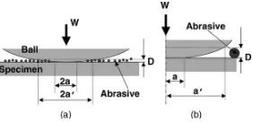
Adachi and Hutchings (2003) performed micro-scale abrasion tests with different combinations of ball and specimen materials, under different test motion. The map was plotted between two dimensionless groups as vertical and horizontal axes; the hardness ratio between the ball and the specimen, and a newly introduced parameter which represents the severity of contact. Their model is shown in figure 6.
(7)
Where is the volume fraction of abrasive in the slurry, and a constant of proportionality.
The critical condition for the transition from grooving to rolling motion, at a certain value of , is therefore
expected to occur at a critical value of contains quantities which are all experimentally
measurable, and can be termed the “severity of contact”, with symbol . It is suggested that the wear model will change from three-body (rolling) abrasion to two-body (grooving) abrasion when exceeds the threshold value . Thus, the transition condition for the three-body (rolling) mode can then be written as
(9)
Where and are empirical constants related to the critical value of and to the constant of
proportionality . For these data, and . and are the hardness of specimen
and hardness of ball, respectively. Where is the interaction area between the abrasive particles and the surfaces of the ball or the specimen.
4 CONCLUSIONS
Finite element simulation is a good method to enable better understanding of grinding process physically. Many FE models have been developed in macro-scale regarding entire grinding wheel-workpiece interaction. The models generally involved heat flux, pressure, and conventional cooling as input process parameters. However, the research on microscale modelling of grinding process, i.e. focusing on individual grain and workpiece interaction, is not quite advanced as expected due to restriction of computing simulation environment. Thus, more researches on micro-scale FE modelling for abrasive processing is required.
REFERENCES
Adachi, K. and Hutchings, I. M. (2003) Wear-mode mapping for the micro-scale abrasion test. Wear 255(1-6) pp: 23-29.
Archard, J.F. (1953) Contact and Rubbing of Flat Surfaces. Journal of Applied Physics 24(8) pp:981-988
Aurich, J.C., Biermann, D., Blum H., Brecher, C., Carstensen, C., Denkena, B., Klocke, F., Kroger M., Steinmann, P., Weinert, K., (2009) Modelling and simulation of process: machine interaction in grinding. Prod. Eng. Res. Devel. Vol: 3 pp: 111-120
Brinksmeier1, E., Aurich, J. C., Govekar, E., Heinzel, C., Hoffmeister, H. W., Klocke, F., Peters, J., Rentsch, R., Stephenson, D. J., Uhlmann, E., Weinert, K. and Wittmann, M. (2006) Advances in Modeling and Simulation of Grinding
Processes. CIRP Annals - Manufacturing Technology 55(2): 667-696.
Brinksmeier2, E., Riemer, O. and Gessenharter, A. (2006) Finishing of structured surfaces by abrasive polishing. Precision Engineering Vol: 30 pp: 325-336
Carslaw, H.S. and Jaeger, J.C. (1959) Conduction of heat in solids (second edition) Claredon Press-Oxford
Chuang, T.-j., Jahanmir, S. and Tang, H. C. (2003) Finite element simulation of straight plunge grinding for advanced ceramics. Journal of the European Ceramic Society 23(10): 1723-1733.
Doman, D. A., Warkentin, A. and Bauer, R. (2009) Finite element modeling approaches in grinding. International Journal of Machine Tools and Manufacture 49(2): 109-116.
Evans, C. J., Paul, E., Dornfeld, D., Lucca, D. A., Byrne, G., Tricard, M., Klocke, F., Dambon, O. and Mullany, B. A. (2003) Material Removal Mechanisms in Lapping and Polishing. CIRP Annals - Manufacturing Technology 52(2): 611-633.
Hahn, F.S. (1962) On the Nature of The Grinding Process. Third International Conference on MTDR pp: 129-164
Klocke, F. (2003) Modelling and simulation of grinding processes. 1st European conference on Grinding, Aachen, 6-7 November
Klocke, F., and Zunke, R. (2009) Removal mechanism in polishing of silicon based advanced ceramics. CIRP Annals-Manufacturing Technology 58: 491-494
Lambropoulos, J.C. Xu, S., Fang, T., and Golini, D. (1996) Twyman effect mechnanics in grinding and microgrinding. Applied Optics Vol: 35 No: 28 PP:5704-5713
Mahdi, M. and Zhang, L., (1995) The finite element thermal analysis of grinding processes by ADINA, Computers and Structures 56 313-320
Mamalis, A.G., Kundrak, J., Manolakos, D.E., Gyani, K., and Markopoulos, A. (2003) Thermal Modeling of Surface Grinding Using Implicit Finite Element Techniques. Int. J. Adv. Manuf. Technol. 21:929-934
Moulik, P. N., Yang, H. T. Y. and Chandrasekar, S. (2001) Simulation of thermal stresses due to grinding. International Journal of Mechanical Sciences 43(3): 831-851.
Trezona, R. I., Allsopp, D. N. and Hutchings, I. M. (1999) Transitions between two-body and three-body abrasive wear: influence of test conditions in the microscale abrasive wear test. Wear 225-229(Part 1): 205-214.
Williams, J. A., and Hyncica A. M. (1992) Abrasive Wear in lubricated contacts. J. Phys. D: Appl. Phys. Vol: 25 pp A81-A90
(a) (b)
[image:7.595.132.465.298.412.2]Figure 1: (a) Process parameters used in grinding (b) General macro-scale thermal model setup (Doman et al (2009)).
[image:7.595.67.271.459.677.2]Figure 3: Comparison of simulation and reality of single grain grinding (Klocke (2003)).
Figure 2: Illustration of (a) rubbing, (b) ploughing, and (c) chip formation phases of material removal by an individual grain
(Hahn (1962))
Figure 4: Material removal mechanism in machining with loose abrasive (Brinksmeier2
[image:7.595.319.523.459.528.2] [image:7.595.327.531.577.674.2]Figure 5: (a) The geometry of a single abrasive particle is described by parameters and , after Williams and Hyncica
[image:8.595.363.504.71.139.2](Trezona et al (1999))
Figure 6: Schematic model showing (a) the interaction area and (b) the magnified view (Adachi and Hutchings