2017 International Conference on Computer Science and Application Engineering (CSAE 2017) ISBN: 978-1-60595-505-6
Analysis of Low-Voltage Centralized Meter Reading Solution Types
and Selection Applications for County
Power Supply Enterprises
Wei Chen*, Lili Sun, Xiaoxia Li and Yeshen He
Zhaoqing Huaiji Power Supply Bureau of Guangdong Power Grid Co., Ltd., Zhaoqing, 526400 Guangdong, China
China Gridcom Co. Ltd, Shenzhen, 518031 Guangdong, China
ABSTRACT
This paper summarizes the communication methods, equipment type, working principle, technical characteristics and interference factors of several mainstream low-voltage electricity information collection system solutions, which are based on the analysis of the existing technical characteristics of the electricity collection system. In this paper, a typical case of the residents' station in the county area is set up. From the perspective of installation environment, equipment cost and communication effect, the paper puts forward three typical technical solutions of the low-voltage centralized meter reading system due to the selection and configuration of the low-voltage electricity information set for different environmental characteristics. Through the application in the rural county grids, the validity and the promotion value of the selection and configuration are verified, which can provide reference for other technical solutions and applications for the construction of low-voltage centralized meter reading system.
INTRODUCTION
system[5], and PLC and the micropower wireless communication are introduced in[6][7].
Based on the above points, this paper will analyze, collate and summarize three typical electricity information collection solutions, which are the type II concentrator[8] solution, combination with the practical situation of domestic smart meters and the mature domestic communication solutions, the type I all-wireless solution, and the type I full-carrier solution. This paper will also put forward a proposal of site investigation and solution selection and the configuration principle, the validity and possible promotional value of which will be verified by the application in the rural county power grids.
RESEARCH AND SOLUTION
Introduction of Technical Solutions of Low-Voltage Centralized Meter Reading System
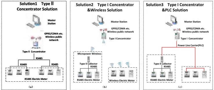
This paper will analyze, collate and summarize 3 solutions of three typical power information acquisition from the actual situation of smart meters and the more mature communication solutions in China. As shown in Figure 1, it can be collated into three typical power information acquisition solutions.
Solution1 TypeⅡ Concentrator Solution GPRS/CDMA etc. Wireless public network Master Station RS485 RS485 RS485
RS485 Electric Meter
(a)
Type II Concentrator
Solution1 TypeⅡ Concentrator Solution GPRS/CDMA etc. Wireless public network Master Station RS485 RS485 RS485
RS485 Electric Meter
(a)
Type II Concentrator
Solution2 Type I Concentrator &Wireless Solution
Master Station
GPRS/CDMA etc. Wireless public network
Type I Concentrator
RS485 Type II Collector
RS485 Electric Meter Micropower Wireless
Wireless Electric Meter
(b)
Solution3 Type I Concentrator &PLC Solution
Master Station
GPRS/CDMA etc. Wireless public network
Type I Concentrator
RS485 Type II Collector
RS485 Electric Meter
Power Line Carrier(PLC)
[image:2.612.124.493.386.541.2](c)
Figure 1. Three typical power information acquisition solutions.
SOLUTION 1: TYPE II CONCENTRATOR SOLUTION
The local communication network equipments of this solution are type II concentrators[8]and RS-485 meters. See Figure 1 (a).
Advantages: Only two types of device terminals, electric meters and type II concentrators, are considered in this solution, which means fewer types of equipments and convenient field maintenance. In addition, the upstream communication way is by GPRS[9] while the downstream communication is by RS-485 wired differential communication. GPRS communication is not involved in networking, so that the troubleshooting method is relatively simple. RS-485 bus has no other signal interference, so the communication is stable and reliable, and can support 10Mb / s high-speed transmission[9].
SOLUTION 2: TYPE I CONCENTRATOR WIRELESS SOLUTION
The local communication equipments of this solution are type I concentrators[8], type II wireless collectors[10], wireless meters, and RS-485 meters.
Work principle: As shown in Figure 1 (b), the master station interacts with type I concentrator through GPRS. After receiving the host command, type I concentrator communicates with electric meters or type II collectors through micropower wireless communication. And type II collectors communicate with meters through RS-485. Concentrators access to meter-related data, collate and then return the master station.
Advantage: This solution is preferred for the short building wall and spacious location (e.g., rural grids, site areas). Wireless type II collectors and RS-485 meters can be used in meters centralized place, while wireless meters are directly used in meters scattered place. Because the wireless network is a self-built networks, the network coverage can be improved by adding the external antenna and the relay in the communication blind spot.
Disadvantage: Sub 1G is a free frequency band and the civilian equipments (such as wireless intercom, wireless TV, etc.) may also use this frequency band, so the network can be easily disturbed. Micropower wireless communication is easily affected by the environment, such as the basement, the iron meter bin, the reinforced concrete wall, etc., which can lead to a dramatic drop in the communication distance.
Solution 2 is suggested when the meters are relatively centralized and the height of the building is less than 15 meters.
Solution 2 is common in low-rise community and rural areas. Meters of one building are installed in a meter bin. The number of meters in the bin is 2 to 10, and there is no other meter bin adjacent to it. Besides, the meters are mostly non-carrier meters. According to the typical solution application and the practical situation, solution 2 with type II collector and RS-485 meters is preferred.
SOLUTION 3: TYPE I CONCENTRATOR POWER LINE CARRIER SOLUTION
Working principle: As shown in Figure 1 (c), the master station interacts with type I concentrator through GPRS. After receiving the host command, the type I concentrator communicates with meters or type II collectors through the power line carrier. And the type II collectors communicate with meters through RS-485 bus. The concentrator reads the data in the meters, rearranges them and then returns all data to the master station.
Advantages: This solution communicates through the existed power line, so there is no need to rewire. It takes the form of wire transmission without occuping the wireless spectrum resources that can reduce the wireless radiation. It is a self-built communication network, which can improve the network coverage by adding the relay in the communication blind spot. In addition, the meters can be identified by the area identification instrument, so that the power company can sort out the consumers.
Disadvantages: With the improvement of living standards, there are more and more household appliances, including some power supply noisy equipment, therefore, a larger load and noise is introduced to PLC environment, affecting the effects of PLC communication.
Solution 3 is suggested when the meters are relatively scattered and the building is more than 15 meters in height.
Solution 3 is common in urban low-rise community, with large meter distance, high stories and small building spans. Electric energy meters,which are smart PLC meters, are basically installed nearby the power users, or in the distribution wells or meter bins. According to the typical solution application and the practical situation, solution 2 with all PLC meters is preferred.
SUBSTATION APPLICATIONS
To combine the advantages and disadvantages, the selection requirements, the proposal selection and configuration principle of the above three solutions, these solutions have achieved good results and promotional value by substation applications.
Area environmental data
The Comparison of the Installation Frequency and the Application Data
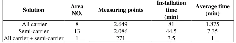
According to the on-site installation data feedback of three solutions, the installation frequency of three solutions is compared, as shown in TABLE I below:
It can be seen from TABLE I that replacing a BCC (broadband carrier communication) module takes about 8 minutes on average in the semi-carrier solution substation area, most time spent on clearing the area line and looking for collector equipments. For a large radius, wide coverage, and equipment replacement difficult area, it can take up to 15 minutes on average to replace a BCC module with self-owned chips. Although replacing modules take a longer average time in the semi-carrier solution, equipments are generally not too many, the overall workload is not too heavy, and the total time-consuming is only 0.5 hour at a minimum and less than 13 hours at a maximum.
It can be seen from TABLE II and TABLE III, replacing a BCC module in the all carrier solution substation area and in the hybrid carrier solution substation area takes about 2 minutes on average. Since most carrier meters are centralized and installed in the meter bin, the communication module can be replaced easily and quickly when changing the communication module. However, in some area carrier meters are scattered and every meter is installed in a single box, thus, most of the installation effort is spent on looking for electric energy meters, disassembling and assembling single meter box, which results in 4 minutes on average to replace a BCC module with self-owned chips in those areas. Although replacing communication modules takes a shorter time on average, considering the large amount of equipments used in the all carrier solution substation, the overall workload of replacing communication modules is still very heavy, the overall time-consuming is less than 3 hours at a minimum and more than 24 hours at a maximum.
TABLE I. INSTALLATION FREQUENCY COMPARISON OF THREE SOLUTIONS.
Solution Area
NO. Measuring points
Installation time (min)
Average time (min)
All carrier 8 2,649 81 1.875
Semi-carrier 13 2,086 44.5 7.35
[image:5.612.107.486.493.563.2]All carrier + semi-carrier 1 271 3.5 1
TABLE II. PERFORMANCE TEST RESULTS OF THE BCC MODULE IN THE HYBRID CARRIER SOLUTION SUBSTATION AREA.
Measuring points
Networking and routing (min)
Channel average delay(ms)
Real-time meter reading
(min)
Average time (s/meter)
Upgrade (min)
TABLE III. PERFORMANCE TEST RESULTS OF THE BCC MODULE IN THE ALL CARRIER SOLUTION SUBSTATION AREA.
Measuring points
Network and routing time
(min)
Channel average delay(ms)
Real-time meter reading
(min)
Average (s/ meter)
Upgrade (min)
158 12 392 5 1.9 20
421 28 471 20 2.85 53
143 12 507 4 1.68 20
476 21 384 14 1.76 77
According to these above data, it can be seen that under different application environments, the three solutions can make different impact on parameters such as project construction timing, network optimization duration, channel average delay, real-time meter reading time and version upgrade time. Therefore, the site environment and construction requirements should be fully considered.
CONCLUSIONS
In this paper, it analyzes the low-voltage centralized meter reading solution for the county power supply enterprises from the aspects of site building constructions, meter types, meter quantity, meter installation environment, power line environment and wireless environment, etc., and puts forward solution selection criteria and principles under three different environments, which have achieved good results in the practical application.
REFERENCES
1. Yiming. H. 2017. “Causes of low voltage in County Power Grid,” Electrotechnical Application, 13:68-72.
2. Weizhi. Z. 2003. “Design of Intelligent Community Automatic Meter Reading System Based on Power Carrier,” Df. Elec. Rev., (2):13-14.
3. Zhiyuan, H, Y. S. and Y. H. etc. 2014. “Adaptability Analysis of Micropower Wireless Communication Technology in Power Line,” Automation of Electric Power Systems, 8:92-97. 4. Xian Z., Changyu W. and Guoping W. 2012. “The Wireless Self-supported Network Technology
Based on the Micro-power Module Applied in the Rural Low Voltage Power Centralized Meter Reading,” Elec. Meas. &Ins., 49(564):38-42.
5. Zhuan Y. 2014. “Design and Development for Management software of Rural Grids Second Voltage Meter Reading System,” Agricultural University of Hebei, 05: 21-30.
7. Chen L. W., and Wang S. L. 2008. “Design and implementation of the low power control circuit in the wireless gas-reading system,” J. Journal of Hefei University of Technology, 25(8):1530-3. 8. Q/GDW 1375.2-2013, Power User Electric Energy Data Acquire System Type Specification, Part 2:
Concentrator, Company Standard of Grid State: 8-10.
9. Guangjiao Y. 2007. “The Design and Implementation of Automatic Reading Meter Information Release System Based on Wireless Network,” Master Thesis of Northeastern University, 2:5-8. 10. Q/GDW 1375.3-2013, Power User Electric Energy Data Acquire System Type Specification, Part 3: