2017 2nd International Conference on Computer, Mechatronics and Electronic Engineering (CMEE 2017) ISBN: 978-1-60595-532-2
Dynamic and Static Characteristics Analysis for Flexible Assembly Cell
Chao SHAO
1,*, Hao WU
2, Zhi-jing ZHANG
1, Xin YE
1and Chen-can HUANG
31
Beijing Institute of Technology, 5 South Zhongguancun Street, Haidian District, Beijing, China 2
Huaihai Industry Group Co. Ltd., 1 Huifeng Street, Changzhi, China 3
Midea life electrical appliance manufacturing Co., Ltd., 19 Le Sanle Road, Shunde District, Foshan, China
*Corresponding author
Keywords: Flexible assembly cell, Modal analysis, Precision microstructures.
Abstract. A flexible assembly cell has been designed for precision microstructures. In this paper, the static analysis and dynamic characteristics of the assembly cell are analyzed respectively. Through the finite element static analysis and simulation, we optimized the assembly cell’s structure design. Through the modal analysis, the first six nature frequencies and nature mode shapes are obtained. The overall oscillation of the first two sections, shows that the asssembly cell has a better dynamic performance. Meanwhile a modal test on assembly cell structure was also conducted. The first-order natural frequency has been obtained. The critical rotating speed is much higher than the maximum speed of the motor in the assembly cell, and no resonance phenomenon can be generated. The simulative results are consistent with the experimental results, and the correctness and adaptability of the simulation method are verified, ensuring the accuracy and reliability of the assembly cell.
Introduction
Nowadays, with the rapid development of precision and ultra-precision processing technology, the mechanism system tends to be miniaturized and microminiaturized in various applications. The demand in the products of micro precision products is rapidly growing, such as, the head of inkjet printer, micro-accelerometer, optical lens and MEMS, etc. For precision assembly of various parts, we set up a flexible microassembly cell to meet the various assembly demand.
In the process of structure design and analysis, finite element analysis is a highly effective numerical analysis method to calculate complex structure0, and the domestic and foreign scholars have done a lot of research in this area. Yu, Lianqing et al. studied the whole machine stiffness through establishing the reasonable combination surface model and whole machine model, through finite element calculation 0. Haiyan carried out the statics and modal analysis of NC vertical machine tool, finding the weak link by finite element analysis 0. Xing-yu zhao, using finite element method, carried on the static and dynamic analysis of milling planer structure, and studied the parts’ contribution to the overall stiffness, providing a theoretical basis for system optimization design[5].
Column and box are the basis of the flexible assembly cell, playing the function of bearing, positioning and connection. Their dynamic and static characteristics directly affect the accuracy and stability of the whole assembly cell 0. In this paper, taken column and box as the research object, we analyzed the static and dynamic characteristics of assembly cell using the finite element analysis software. And the correctness of the analysis were verified by modal test, finding the weak link and optimizing the structure.
The Flexible Assembly Cell
module and column were installed on the box; the assembly execution module was installed on the column; the micro adjustment module was installed in the box. By developing the flexible microassembly cell, meso-scale parts can be assembled by a sequential process of grasping, manipulating and inserting.
Flexible assembly cell
Column
Box CCD module
Assembly excution module
[image:2.612.180.425.125.281.2]Adjustment module Prism module
Figure 1. The flexible assembly cell with coaxial alignment function.
Static Analysis and Structure Optimization
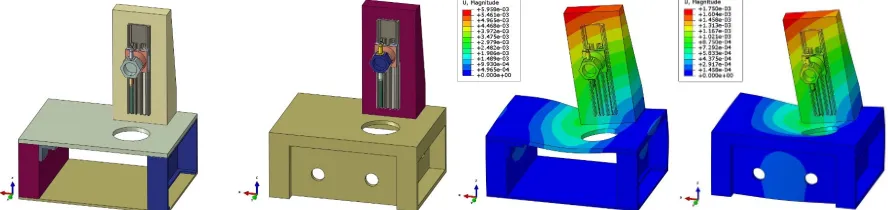
In order to simplify the calculation, the vision system module, and the coupling, screw, bearing and motor parts could be neglected. After simplification in PROE software, the model was introduced to the finite element analysis software. As shown in Fig.2, there are two kinds of box structure. Fig.2 (a) is the plan 1 that the box body was set up by steel plates through screw joint; Fig.2 (b) is the plan 2 that the box body is directly casted. In both two plans, the completely constraints were imposed on the bottom of the box body, and the gravity load was applied to whole model, which was in the negative direction of z axis. The deformation contours of two plans were shown in Fig.2(c), (d), respectively. By comparing two kinds of schemes, the deformation of plan 2 is smaller than plan1, explaining that the plan 2 is superior to plan 1. Similarly, the stress cloud shows that the large stress region of plan 1 is more than plan 2, indicating that the overall structural stiffness of plan 2 is better than that of plan 1. And the box casted is also more accurate than the accuracy of the box through plan l, so the casting structure is selected.
(a)Box body made up of steel plates (b) Box body casted (c)The strain contours of plan 1 (d)The strain contours of plan 1
Figure 2. Two kinds of box structure and their strain contours.
Dynamic Characteristics Analysis
[image:2.612.84.528.504.609.2]The modal experimental principle is shown in Fig.3. Hammer hit the column structure, causing the excitation signal to transfer in two directions. One signal sensed by force sensor, was magnified and transferred to signal acquisition instrument by Chanel 1; the other signal sensed by accelerometers on the column, was magnified and transferred to signal acquisition instrument by Chanel 2, 3, 4. The signal acquisition instrument synthetically processed the two signals and sent data to the computer. The DSP software performed data analysis of the two signals, and the modal parameters of the column would be obtained.
Flexible assembly cell
Force sensor
Charge amplifier Signal acquisition instrument Charge amplifier
Accelerometer
DSP Data processing Voltage
signal
Voltage signal
CH1
CH2,3,4
Voltage signal Voltage signal
[image:3.612.170.455.163.310.2]USB
Figure 3. The modal test principle of the flexible assembly cell.
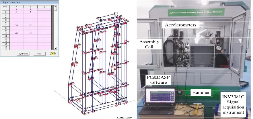
Before the experiment, we should distribute points on the column structure. Distributing points should be complied with the following principles: the distributing points can make modeling be more convenient and can reflect the structural vibration characteristics easily; try to involve all orders’ modal vibration form; must cover all the key points; stagger the vibration node; easy to install the acceleration sensor. DASP modeling and distributing points are shown in Fig.4. The modal experiment test system is shown in Fig.5. According to the distributing points in DASP modal, hit the column with hammer in turn, and collected the incentive and response signal. Based on the amplitude and phase of vibration signal, and the correlation of input and output function, we could judge the reliability of the experimental results. Besides, correlation coefficient is also a key indicator to judge the reliability of the experimental modal analysis based on the results of frequency response function (FRF) caculation, as shown in Fig.6.
Accelerometers
PC&DASP software
INV3081C Signal acquisition instrument Hammer
[image:3.612.87.528.487.696.2]Assembly Cell
Figure 6. The results of frequency response function (FRF) caculation.
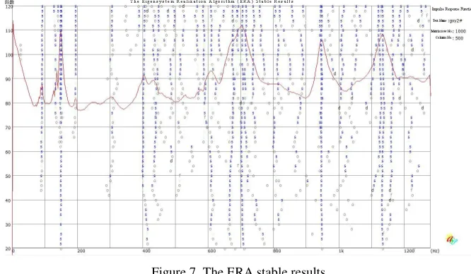
This experiment adopts eigensystem realization algorithm(ERA) to complete modal parameter identification.The Fig. 7 shows the Eigensystem Realization Algorithm (ERA) stable results. Based on this method, the modal parameter can be obtained accurately and reliably [8].
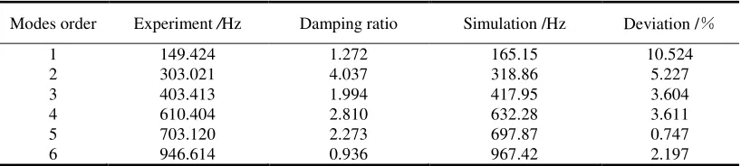
Using ANSYS software, modal simulation analysis was carried out on the column, and 6 order modal frequency and modal vibration mode were extracted. Due to the low frequencies have bigger influence, only the sixth-order modal vibrations were extracted. The modal simulation and experimental results were compared, as shown in Table 1. By the contrast of the data, it can be found that the real inherent frequency is generally greater than that of simulation, and the maximum deviation of frequency is about 10.524%. The reasons causing the difference are as follows: the connections between surface and surface nodes of parts in finite element simulation model are bonded, increasing the structure’s stiffness; actual installation stiffness of structur assemblycell is less than the stiffness designed.
Figure 7. The ERA stable results.
On the whole, the natural frequencies of the assembly cell are basically consistent with the experimental results, which proves that the modal experiment and simulation method is applicable. At the same time, it can be seen from the simulation and experimental data that the basic frequency of the assembly cell is higher, which is difficult to resonate. The critical speed of the moving mechanism of the assembly cell is calculated based on the 1 order natural frequencies, and the V0 =149 * 60=8940
r/min is obtained. The motors’ maximum speed of assembly cell is assembly excution platform is 2400r/min, whicn is far less than the critical speed of V0. In the process of assembly, the motor will
[image:4.612.136.469.437.631.2]Table 1. The experimental and simulation results.
Modes order Experiment /Hz Damping ratio Simulation /Hz Deviation /%
1 2 3 4 5 6 149.424 303.021 403.413 610.404 703.120 946.614 1.272 4.037 1.994 2.810 2.273 0.936 165.15 318.86 417.95 632.28 697.87 967.42 10.524 5.227 3.604 3.611 0.747 2.197 Conclusion
In this paper, the flexible assembly cell for precision structures was introduced, and the mechanical performance of the assembly cell was analyzed. The results of simulation and experiments proved that the system has good static stiffness and dynamic characteristics.
The static mechanical characteristics of the assembly cell were analyzed by the finite element simulation analysis. The maximum deformation of body made up of steel plates and box body casted, under the gravity load, were 5.958 and 1.750um respectively, proving the superiority of casting type. Based on the results of caculation, we have carried out 4optimization design. Further, the modal analysis of the assembly cell was carried out, and the 6 order modal shapes and natural frequencies of the element were obtained. The modal experiment was carried out by means of vibration measuring instrument, and experimental result was larger than simulation results about 10.524%, which proved the applicability and correctness of the modal simulation method. Based on the 1 order modal frequency, the critical speed of motion of assembly cell, which was far higher than the highest speed unit in 2400r/min. In the process of assembly, the motor would not produce resonance phenomenon, ensuring the accuracy and reliability of the assembly cell.
Acknowledgements
This work was financially supported by the National Natural Science Foundation of China (51575052).
Reference
[1] Liu, Jiang, and Chuan-jun Tang. "The Dynamic Analysis and Structure Optimization for Bed of NC Machining Center." Modular Machine Tool & Automatic Manufacturing Technique, 2010(4): 20-22, 25.
[2] Shi Jian, Han Bo, Wang Ke. “FEM -based dynamic design of Kelly machine bed.” Mechanical Engineer, 2010(2):35-37.
[3] Yu Lianqiang, Wang Liping. Stiffness analysis of machine tools using finite element method. 3rd International Symposium on Intelligent Information Technology Application, 2009, 3: 553- 556.
[4] Shu Hai-yan, He Cheng-zhu, Wang Xiao-lin, Hou Li-xuan. “Finite element analysis of CK5116 CNC lathe as a whole.” Manufacturing Automation, 2012(6): 84 -86.
[5] Zhao Xing- yu, Zhang Da-wei. “The Analysis of the Characteristic of the Dynamic and Static of the X2012C Machine Tool.” Modular Machine Tool & Automatic Manufacturing, 2005(10):84- 86.
[6] Ye, Xin, Jun Gao, and Zhi Jing Zhang. “A microassembly system with coaxial alignment function.” Applied Mechanics and Materials. 2014(487):678-681.