2017 2nd International Conference on Computer, Mechatronics and Electronic Engineering (CMEE 2017) ISBN: 978-1-60595-532-2
GGPRF: AGPU-Based Generic Parallel Rendering Framework
Juan ZUO
1, Feng JIANG
2, Zhi-jie LIN
3,*, Hai-feng HUANG
1and Qin-fei ZHANG
21
China Electric Power Research Institute, China
2
The College of Computer and Science of Zhejiang University, China
3Zhejiang University of Science and Technology, China
*Corresponding author
Keywords: GPU cluster, Parallel rendering framework.
Abstract.With the development of CUDA architecture and GPU technologies, parallel rendering
technologys have been developed rapidly. There are already some parallel rendering frameworks, such as Chromium, MPK, VR Juggler, etc., but these systems have obvious flaws.In this paper,GGPRF: a GPU-Based Generic Parallel Rendering Framework is proposed. The framework contains three roles, Master, Server, and Slave, which are responsible for rendering task drivers, cluster management, and rendering. Server manages the entire parallel rendering system's organizational structure through the NTTree (Network Topological Tree) data structure. GGPRFhas improved the shortcomings of the existing universal parallel rendering framework, which has the advantages of universal, extensibility and ease of use. In this paper, the design of the frame is described in detail and the experiment is tested.
Introduction
For complex 3D models, although existing technologies can improve rendering performance to some extent, these technologies have not yet fully exploited the parallel computing power of computer hardware. Cluster based parallel rendering technology can take advantage of the computing power of many machines and greatly improve the rendering speed. But the current cluster parallel technology is mostly based on CPU. GPU cluster based parallel technology and system are just starting up, and there are still many problems.
Parallel rendering architecture is the core issue of parallel rendering platform. It determines the performance, function and behavior of the whole platform. How to design a reasonable and efficient parallel rendering architecture is one of the issues that need to be studied? At present, most of the parallel rendering frameworks can only be applied to specific scenarios, which are not universal, poor scalability, and unreasonable in design, which cannot make full use of computing power of computing resources.
Aiming at the above problems, based on the existing real-time parallel rendering technology related work, this paper proposes a parallel rendering architecture based on improved GPU cluster general, the parallel rendering framework has advantages in rendering performance, versatility, scalability and application etc.
The Structure of GPU-Based Generic Parallel Rendering Framework
This paper presents a GPU-Based Generic Parallel Rendering Framework, which uses the NTTree data structure to ensure the versatility, extensibility and accessibility of the framework. GGPRF has the following advantages over the existing common parallel rendering framework:
interfaces, GGPRF achieves the separation of render frames and renderings. GGPRF only needs to focus on the implementation of the underlying work, such as network communication, synchronization, result synthesis, etc. The renderer only needs to focus on the implementation of the rendering itself, without the need to focus on the underlying implementation.
Compare with Chromium, GGPRF does not transmit Opengl render commands on the network and only transmit the necessary synchronization commands, rendering data, and rendering results which reduces the network overhead in the rendering process and certainly improve the rendering performances. Anotherbenefit of not transmitting the Opengl command is that GGPRF can support rendering in other ways, instead of being limited to Opengl methods.
Compare with MPK, GGPRF adopts the method of data parallelism, unlike MPK which uses the method of function parallelism, so GGPRF has higher parallelism. It is worth mentioning that GGPRF borrowed the Compound structure used in MPK and proposed the NTTree tree structure. NTTree records all resource information in the system, and can dynamically manage the addition and removal of resources. NTTree can flexibly define the organization way, resource allocation strategy and collaboration method of computing resources through hierarchical structure, and can specify arbitrary resource nodes to output rendering results. Through NTTree, the generality, extensibility and ease of use of GGPRF have been improved.
GGPRF is a framework based on software architecture and is built on distributed memory structure. The framework adopts the method of data parallelism, and supports multiple parallel rendering pipelines, task segmentation, synthesis strategy and load balancing strategy. The frame design takes into account the continuity problem (including space and time continuity). The design of GGPRF can be divided into two aspects: node hierarchy and framework runtime logic structure.
Node Hierarchy
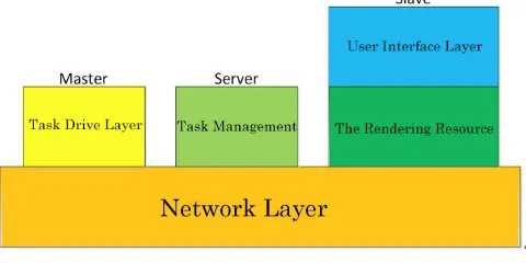
[image:2.612.188.428.435.555.2]The node hierarchy describes the abstract ways of each communication node. According to the function, communication nodes can be divided into three roles, Master, Server and Slave who are responsible for rendering task drive, task management and rendering.
Figure 1. Framework hierarchy.
The hierarchy of nodes is shown in figure 1, each of which abstracts specific physical resources or implements specific functions. The five levels shown in the figure are integrated into the same executable, and the executable file is entered into the corresponding hierarchy depending on the role specified by the configuration file. If an executable is configured as Master, then it will enter the task-driven layer; if it is configured as Server, it will enter the task management. If it is configured as Slave, then it will enter the render resource layer and call the render function that the user defined in the user interface layer.
The network layer is the lowest level in all layers, Shared by Master, Server and Slave, and responsible for internode communication. The network layer realizes all functions related to network communication in GGPRF, including linking and closing, connection management, network command management, network data objects and synchronization;
The task management implements Server's primary function, which USES a NTTree (described below) to record the available resources, manage the decomposition of tasks, and the allocation of resources. Master of every order first sent to the Server, the Server will traverse NTTree after receives the command structure, according to NTTree describe the hierarchical structure of the command parsing into a series of commands, and forwarded to the corresponding node command.
[image:3.612.226.398.203.316.2]The rendering resource layer is used to abstract the physical rendering resources (computer, graphics card, etc.), which implements the main function of Slave. The abstract level of a computer in the rendering resource layer is as follows: computer -> graphics card -> window -> cache. A computer can have multiple graphics CARDS, a graphics card can have multiple Windows, a window can have multiple caches. Figure 2 is the hierarchy of a computer:
Figure 2. Renders the resource layer hierarchy.
The user interface layer defines the interface between GGPRF and render code. The user interface layer provides a set of user interfaces that users can override to implement custom rendering methods.
The main entry provided by the user interface layer is a factory class whose name is UserRender. There is a series of CreateFunction in UserRender.
[image:3.612.148.460.429.517.2]The creation function is a series of hierarchical functions corresponding to the hierarchical structure of rendering resources, as shown below in Table 1:
Table 1. UserRender class.
Overloading the above interface allows you to customize the rendering mode. GGPRF greatly reduces the coupling of code with rendering code by providing a user programming interface.
Runtime Cluster Structure
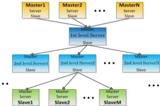
The runtime structure of the system is shown in Figure 3.The Master, Server, and Slave are organized by a certain hierarchical structure. The Server is in the middle tier, and Server manages all rendering resources through NTTree, and describes the decomposition of tasks and the allocation of resources.
Figure 3. System runtime structure. Class UserRender
{
[image:3.612.225.382.625.729.2]The nodes in the GGPRF framework are divided into three roles: Server, Master and Slave. The network communication relationship of the three is shown in Figure 4:
Figure 4. Communication between master, Server and Slave.
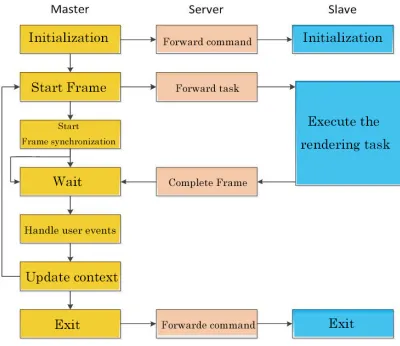
The Master initiates a task and sends out initialization, frame start, frame synchronization commands throughout the rendering process; Server is used to receive and forward Master commands, decompose composite rendering tasks, allocate rendering resources, and control the coordinated operation of all Slave. Slave is only responsible for processing assigned rendering tasks. Here are three specific jobs:
Master: If an executable is specified as Master, the program enters the Master task loop and
becomes a Master node. The Master is a task request node that drives the GGPRF for rendering tasks. The Master does not render work, which is responsible for sending commands to render various stages, including initialization, frame start, frame synchronization, and so on. The Master will first issue the initialization command to Server, Server traverses the NTTree tree, and forwards the command to the corresponding Slave node at the corresponding level, initializing all relevant nodes; The Master then sends a frame to the Server to start the command, and the Server will also traverse the NTTree tree and issue the render context update commands and corresponding rendering tasks to the corresponding Slave according to the hierarchy. Finally, the Master sends the frame synchronization command to itself to enter the waiting state until all the rendering results are sent to the composite node and the final result is synthesized. The above several command execution is completed, the Master node will collect on each node (including yourself) user events, and to deal with events, update rendering context, and then into the next cycle.
Slave: If an executable is specified as Slave, the program enters the Slave task loop and becomes a
Slave node. The way the Slave joins the cluster is different because of the Server's operation mode. Under Stable Mode, Slave is requested to join the cluster by Server request; Under Scalable Mode, Slave initiatively joins the Server join the cluster.
A Slave node, which is Shared by three roles, except the command to receive and assign threads, and a Computer thread, is the main thread of Slave; One or more GraphicsCard threads, every GraphicsCard thread corresponding to a graphics card, rendering work performed by the GraphicsCard thread.
Server: If the executable is specified as Server, then the executable will enter the Server loop and become a Server. Server is the intermediate between three network roles, which is responsible for command communication between Master and Slave, and manages all Slave collaboration methods. Server will receive the first initialization command message from the Master Server, upon receiving this command, according to NTTree to connect Slave nodes are available, and will send all Slave nodes after connection initialization command and initialized data. After the initialization phase is over, the Server will forward the frame at the NTTree level to start the command until a single frame task is completed and then enter the next loop.
Server maintains an NTTree tree that describes the GGPRF task decomposition synthesis and resource allocation methods. NTTree is the core data structure of GGPRF, which guarantees the extensibility of the parallel rendering framework. Server can be read from the local NTTree, if create NTTree tree in this way, then the clustering into Stable Mode, the topology of the cluster according to read NTTree content and determine, after will not be changed; Server can also choose to automatically create NTTree, if create NTTree tree in this way, then the clustering into Scalable Mode, if enter this mode, so if there is need to join the new node in the cluster, can connect to the Server, the Server will join the node to its maintenance NTTree, NTTree tree in this mode can be dynamic extensions.
Network Topology Tree NTTree
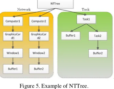
Server controls the way the tasks are decomposed and the distribution of the rendering resources through NTTree. NTTree is a tree structure divided into two parts. The first part records the resource structure in the cluster rendering system. The second part is the Task decomposition and Task structure, which describes the Task decomposition and synthesis method. NTTree is stored on the Server side, and the Server side can control the establishment of NTTree with StableMode and ScalableMode. NTTree's resource structure describes the resource information available in the cluster, which is an abstract description of physical devices, including Computer, GraphicsCard, Window, and Buffer; The Task structure describes how rendering resources work together for a rendering Task.
[image:5.612.216.405.548.696.2]At the top of the resource structure, Computer represents a machine on the network; the following is the GraphicsCard, which represents the GPU; there's a Window in the GraphicsCard that represents a render Window; there is also Buffer under Window, which represents a specific rendering task. As shown in figure 5, the resource structure of NTTree indicates that there are two computers in the system. Each computer has a video card, and each card has a window, and there is a render storage in one window. The Task structure indicates that there is a Task Task1 in the system, which is composed of the results of Buffer1 and Task2, and the result of Task2 is Buffer2. Resource information in Task structure corresponds to resources in resource structure through name information.
Figure 5. Example of NTTree.
traversal process, Server sends rendering tasks to all nodes that bear the render task, and all nodes that receive the render task enter the render process. Follow-up after prior sequence traversal process, this process need to use the synchronization mechanism, the process, all the Task structure on the synthesis of Task Node Task synthesis work from down to up, wait for the synthesis of the top Task to complete, the whole frame of rendering Task is complete.
Experimental Result
This chapter makes an experimental analysis of GGPRF parallel rendering architecture. The device is used for dawning rendering workstation, Gigabit switch, network is gigabit network, and the configuration of Dawning rendering workstation is as follows:
CPU 4 coreXeon e5620 2.4GHz
Memory 12GB
graphics card NVIDIA GeForce GTX 480
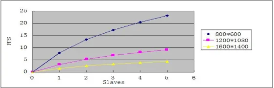
[image:6.612.166.447.317.407.2]The number of the model faces is 8 million. We adopted the simplest task decomposition synthesis form, and adopted the way of uniform partition based on screen space. The frame rate was counted in the case of ray tracing and rendering under the condition of different resolutions and number of nodes. The statistical results are shown in Figure 6:
Figure 6. Performance analysis of Stable mode
As can be seen from the chart as the resolution increases, the rendering speed is decreased with the increase of geometry; rendering nodes, rendering the overall performance of a growing trend, but more nodes, the slower growth trend, which is mainly due to the node increases, the overhead of network communication, node management increased by. And in this test, we use dynamic load balancing strategy instead of uniform screen space. If we use the dynamic load balancing strategy, we will further improve the performance. From the rendering performance, the performance of the cluster is ideal, which is in line with our expectations.
Acknowledgement
The article was supported by the project of "Intelligentcontrolplatform architectureand real-timetransparentaccesstechnology. (No. 2017YFB0902601)" and Zhejiang Province Project"Research on the key technology and system development of automatic generation of video virtual viewpoint for security monitoring".
Reference
[1] Humphreys, G., et al. Chromium: a stream-processing framework for interactive rendering on clusters. in ACM Transactions on Graphics (TOG). 2002: ACM.
[2] Bhaniramka, P., P.C.D. Robert and S. Eilemann. OpenGL multipipe SDK: A toolkit for scalable parallel rendering. in Visualization, 2005. VIS 05. IEEE. 2005: IEEE.
[4] Allard, J., et al. Net Juggler: running VR Juggler with multiple displays on a commodity component cluster. in Virtual Reality, 2002. Proceedings. IEEE. 2002: IEEE.