2017 2nd International Conference on Manufacturing Science and Information Engineering (ICMSIE 2017) ISBN: 978-1-60595-516-2
Simulation and Optimization Analysis of
Clinching Joint Performance Based on
Mould Parameters
Baijun Shi, Zhaoyuan Zhang, Mengyu Yang and Jiabin Zhong
ABSTRACT
In order to improve the quality of clinching joint, the parameters of mould should be considered synthetically. In this paper, the Hollomon flow stress model is used to simulate material deformation, while Arbitrary lagrangain-Eulerian method to adjust the distorted meshes for improving the accuracy of finite element simulation. The experiment of multi-objective optimization and finite element simulation method are combined to study the relationship underneath between the mould parameters and quality of clinching joint. As two of the most important quality related indicators, the neck thickness and self-lock value of clinching joint are optimized by the genetic algorithm and the optimal solution of the mould parameters are obtained accordingly. The final experimental results show the obvious quality improvement of clinching point after the optimization of the mould parameters. This progress provides reference for the multi-parameter optimization of the mould.1
INTRODUCTION
With the increasing demand for environmental quality, it is an inevitable trend to reduce the emission of automobiles. Automobile lightweight is one of the important ways to reduce fuel consumption. So in order to ensure market competitiveness, using some lightweight high-strength materials to replace the original steel plate material will effectively take both into account. The clinching joint can be simple and efficient to achieve the connection between different plates, while the clinching joint is high reliability and high efficiency.
1Baijun Shi, Zhaoyuan Zhang, Mengyu Yang, Jiabin Zhong, South China University of
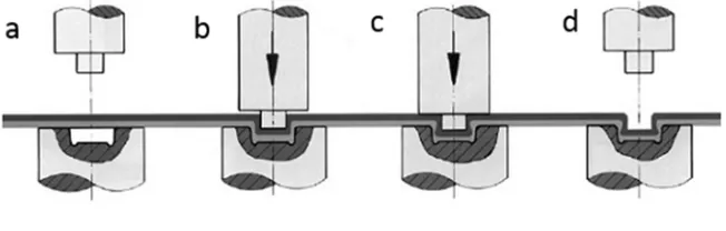
The clinching technology can self-locking after plastic deformation, so during this progress complete the connection. The progress contains four steps: fast positioning, sheet pressing into mould, punch forming connection point, and punch return, as shown in Figure 1.
[image:2.612.138.464.460.564.2]During the research process of pressure connection, J.P. Varis confirms that circular pressure connection point is better than mechanical performance through the experiments of square and circular pressure connection point of difference in mechanical properties [1]. At the same time, he deeply studied the relationship between the shear strength of the pressure connection point and the geometric parameters of the mould, and put forward the selection of the mould parameters by using the volume algorithm [2]; J. Mucha discuss the relationship between the die parameters and the flow of material and the stress distribution at the bottom of the pressure connection point in the process of the pressure connection. through doing a large number of experiments and changing the geometric parameters of die, such as punch radius, concave groove shape, etc[3] E. Roux, P.O. Bouchard put Lemaitre damage model in pressure connection finite element simulation model and used Kriging model to optimize the mechanical properties. The experimental results shown that the mechanical properties of the optimized pressure connection point had been significantly improved [4].Recently, new materials are being used on the car body. M.M. Eshtayeh illustrated the application of riveting and traditional connection in different materials, and given some advice of the clinching [5]. And Xiaocong He investigated the performance of clinching joint whose material is titanium. The results show that the failure mode of titanium alloy joint is neck fracture, and the performance is better when it is used as upper plate [6].
Figure 1. Clinching Progress.
a, fast positioning; b, sheet pressing; c, punch forming connection point; d, punch return
multi-objective optimization method to optimize each parameter of the die is in order to find the optimum solution and improve the performance of high pressure connection.
ESTABLISHMENT OF FINITE ELEMENT MODE
Establishment of Material Model
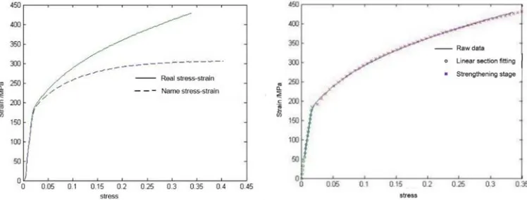
This paper adopts 45# steel as the material analysis, the elastic modulus is 189420MPa, Poisson's ratio is 0.3, the density of the material is 7.8E 009kg /mm . The material has obvious plastic deformation in the process of pressure connection. In order to establish the simulation model accurately in ABAQUS, the standard tensile experiment of 1mm thick 45# steel is designed to obtain Force-Displacement relationship and the true plastic strain and stress of the material in ABAQUS are calculated by using mathematical relation. As shown in Figure 2. As it shown, the true stress and strain before the local deformation are more accurate, and the strengthening stage cannot be well simulated.
[image:3.612.109.483.457.599.2]Hollomon flow stress model can better approximate the real stress-strain relationship of the calculated material, and the fitting equation has a larger correlation coefficient. So the Hollomon model is used to simulate the strengthening stage of the material, and the relationship curve is fitted in MATLAB, as shown in figure 3. It can be seen from the figure 3 that the fitted flow mechanics model can better approximate the actual stress and strain of the material, and improve the accuracy of the finite element simulation model of the pressure connection.
Geometric Model Establishment and Boundary Condition Setting
The mold is axisymmetric, and its geometry is shown in Figure 4. Therefore, the axisymmetric model of the components such as plate and punch is established in the software. Because the punch, the die and the blank holder are parts of high hardness, their shape variables are very small in the process of the pressure connection, so they are simulated as analytical rigid bodies. According to the deformation of each part, the model is partitioned into different regions, as shown in Figure 5. In order to improve the efficiency of simulation analysis, the friction coefficient of each contact pair is set to 0.1. According to the steel wave velocity 5000m/s, the simulation loading speed is less than 50m/s. The press stroke and press time can be calculate by formula (1) and (2). At this point, the kinetic energy of the plate exceeds 10% of the internal energy. Therefore, the connection process is not quasi static, so the stamping time is set t =0.0002s.
X H T T
S u d d (1)
v S
t = (2)
The X is the bottom thickness of the press connection point after stamping forming, and the V is the stamping speed.
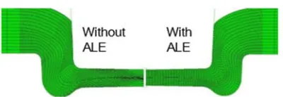
In the simulation process, the deformation of the plate is large, and even if the mesh region is reasonably divided, the mesh distortion may occur. In order to prevent the occurrence of grid distortion, the ALE method (Arbitrary lagrangain-Eulerian) is used to adjust the mesh distortion [7], and the simulation results are compared with those shown in figure 6.
Figure 6. Grid contrast before and after adjustment by ALE method.
MULTI-OBJECTIVE OPTIMIZATION OF MOULD PARAMETERS
Model Parameterization
The mold shape is complex, so before the multi-objective optimization of the mold, firstly it need to parameterize the mold. During this progress, selecting the factors have great influence on the forming quality of the pressure connection point, neglecting some secondary factors [8]. Selecting the fixed value for the chamfer size is also useful. These simplifications are convenient for multi-objective optimization of die parameters.
The neck thickness tn and self-locking value f (as shown in Fig. 7) can
preferably reflect the mechanical properties of the clinching joint after molding [9]. That is to say, the mechanical properties of the joint can be characterized by the neck thickness and self-locking value. The simulation results after molding as shown in Figure 8, and it can be seen that mould geometry and Stamping stroke of punch and can basically determine the clinching point after stamping forming geometry, and it can also determine self-locking neck thickness after clinching. To some extent, it’s also reflect the mechanical properties of the connection point.
Therefore, the geometry of male mould is parameterized by the radius of the die
p
R
, and the geometry of the female die is parameterized by the radiusRd, depthHd,
[image:5.612.117.464.543.655.2]the depth of the grooveHg, the width of die grooveWg.
The Parameters Range of Multi-objective Optimization
The bottom thickness of the press point can also reflect the punch stroke of the punch. Therefore, in order to determine the parameters of the multi-objective optimization, the stamping thickness X is replaced by the bottom thickness Hc
after punching forming.
[image:6.612.117.480.593.688.2]Through the analysis of the cross-section shape of clinching joint, the range of each parameter is shown in TABLEI.
TABLE I. PARAMETERS RANGE OF MOULD.
p
R /(mm) Wg/(mm) Hd/(mm) Hg/(mm) X /(mm)
2.4 1.2 1.2 0.2 0.6
2.8 1.6 1.6 0.5 0.8
Test Process of Multi-objective Optimization
ESTABLISHMENT OF RESPONSE SURFACE EQUATION
The response surface equation of neck thickness and self-locking value should be established firstly during the multi-objective optimization [10]. So the central composite experiment (CCD) with neck thickness and self-locking value was established by using Design-expert software, and then The finite element simulation of each set of tests was carried out by ABAQUS software. According to the result of simulation, the neck thickness and self-locking value of each group will be recorded. At last, it can be obtained by Design-expert software that the response surface equation of neck thickness and self-locking value.
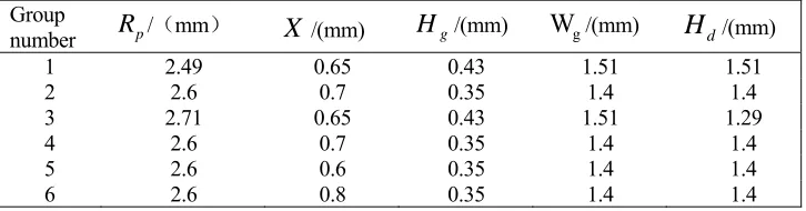
The more the test group, the more accurate, but the lower the efficiency. In this paper, a small scale experiment is used, 26 groups are tested to meet the requirements, the experimental arrangement as shown in TABLEII, the simulation results as shown in Figure 9 (due to excessive data, only 6 sets of experimental data provided here).
TABLE II. MULTI-OBJECTIVE OPTIMIZATION TEST SCHEDULE. Group
number Rp/(mm) X /(mm) Hg/(mm) Wg/(mm) Hd/(mm)
1 2.49 0.65 0.43 1.51 1.51
2 2.6 0.7 0.35 1.4 1.4
3 2.71 0.65 0.43 1.51 1.29
4 2.6 0.7 0.35 1.4 1.4
5 2.6 0.6 0.35 1.4 1.4
Figure 9. Finite element analysis results of multi-objective optimization test.
According to test, the neck thickness and self-locking value of the pressure connection point are shown in TABLE III after each stamping.
TABLE III. NECK THICKNESS AND SELF-LOCKING VALUE OF EACH GROUP.
Group f
n
t Group f
n
t
1 0.089 0.304 4 0.15 0.352
2 0.15 0.353 5 0.215 0.353
3 0.166 0.361 6 0.091 0.351
So it can calculate the respond equation of self-locking value and the neck thickness by using the Design-expert software analysis module. It’s shown as formula (3),(4). 2 5 2 4 2 3 2 2 2 1 5 4 5 3 4 3 5 2 4 2 3 2 5 1 4 1 3 1 5 4 3 2 1 153 0 053 0 516 0 439 0 228 0 238 0 299 0 894 0 573 0 940 0 495 0 606 0 835 0 184 0 094 1 499 3 876 1 894 0 961 1 269 4 x . x . x . x . x . x x . x x . x x . x x . x x . x x . x x . x x . x x . x . x . x . x . x . . f (3) 2 5 2 4 2 3 2 1 5 4 5 3 4 3 5 2 4 2 3 2 5 1 4 1 5 4 3 2 1 326 0 023 0 201 0 376 0 069 0 213 0 177 0 154 0 266 0 762 0 707 0 070 0 086 1 218 0 176 1 844 0 661 0 195 0 x . x . x . x . x x . x x . x x . x x . x x . x x . x x . x x . x . x . x . x . x . . tn (4)
OPTIMIZATION OF GENETIC ALFORITHM BASED ON INSIGHT
The genetic algorithm selects the spatial points randomly and does not require the continuity of the function, so it is suitable for multi-objective optimization of the clinching joint. In the INSIGHT software optimization module, the neck thickness
1 2 3
[image:7.612.95.488.348.410.2]and locking value are selected as the optimization objectives, and set self-locking value greater than 0.18, neck thickness greater than 0.4. Some the optimized partial Pareto solution set is shown in TABLE IV.
TABLE IV. PARTIAL PARETO SOLUTION SET.
f
n
t
2.612574 0.600582 0.369773 1.436194 1.257076 0.199998 0.406205 2.599598 0.600524 0.349874 1.436196 1.269473 0.200103 0.406064 2.609574 0.600583 0.349771 1.436241 1.259043 0.199996 0.406217 2.609475 0.600579 0.359772 1.436194 1.269078 0.199972 0.406235 2.599574 0.600515 0.349819 1.436839 1.269139 0.200214 0.406193 2.599189 0.600515 0.369977 1.436194 1.269112 0.199943 0.406309 2.599189 0.600515 0.599771 1.436177 1.269112 0.199944 0.406309
Taking into account the actual situation of the mold and the wear of the mould, the parameters are optimized to two points after the decimal point, and the parameters of the die, the self-locking value and the neck thickness are measured and adjusted through the repeated adjustment and Simulation of the parameters, as shown in TABLEV.
TABLE V. GEOMETRIC PARAMETERS OF DIES. U-plate D-plate
p
R /(mm) X / (mm) Hg/ (mm)
1 1 2.6 0.6 0.35
g
W / (mm)
d
H / (mm) f / (mm)
n
t / (mm)
1.43 1.27 0.192 0.402
Results Analysis
According to the above analysis, the finite element simulation of the pressure connection is carried out, and the results before and after kick-back are shown in figures 10 respectively. It can be seen from figure that the material is completely filled with the concave die before the kick-back, and the upper part is tightly connected to the punch.
equation of self-locking value and neck thickness is relatively accurate, on the other hand, the response surface equation is better for data point fitting.
COMPARISON OF EXPERIMENTAL AND SIMULATION RESULT
Pressure Connection Test
[image:9.612.132.461.145.222.2]This experiment select 1mm thickness as the upper and lower plate. In order to verify the performance of the optimized die, two sets of molds were selected to test. The first group was selected as the first group in the multi objective optimization, and the optimized die was used as the second group. The die parameters are shown in TABLE VI, and each experiment is done 3 times to eliminate the experimental errors caused by some accidental factors.
TABLE VI. GROUP AND EXPERIMENTAL DIE PARAMETERS. Group
p
R /(mm) X /(mm) Hg/(mm) Wg/ (mm) Hd/(mm)
1 2.71 0.6 0.43 1.51 1.29
2 2.6 0.6 0.35 1.43 1.27
The cross section of the specimen was obtained by wire cutting, and then carry out the tensile and shear tests. The results show that the optimized clinching joint has better performance, and the tensile and shear test results are shown in TABLE VII.
TABLE VII. EXPERIMENTAL AND SIMULATION OF tn AND f .
Group n
t f
Actual value
Average value
Simulation value
Actual value
Average value
Simulation value
1 1# 2# 0.343 0.338 0.340 0.361 0.149 0.155 0.152 0.166
3# 0.340 0.153
2 1# 2# 0.378 0.383 0.381 0.402 0.177 0.179 0.178 0.192
3# 0.381 0.178
Analysis of Experimental Results
The size of the cross section obtained by wire cutting is shown in the figure 11. Compared with the corresponding simulation results, it’s found that the experimental results are approximate to the simulation results. Therefore, the simulation results are reliable.
Group 1 Group 2
Figure 11. Comparison of wire cutting and simulation results.
The neck thickness and self-locking value of the clinching joint are calculated and measured, as shown in TABLE VIII. It can be seen from the table that the deviation of neck thickness and self-locking value of the first groups were 5.8% and 8.4%, and the deviation of neck thickness and self-locking value of the second groups were 5.2% and 7.3%. Considering the factors such as the precision of the die processing and the dimension error of the plate in the experiment, the experimental results show that the simulation results are reliable in a certain range of error, so the parameters obtained by the finite element simulation can basically reflect the actual situation.
[image:10.612.115.475.358.445.2]strength is not obvious. It has been proved that the high quality pressure connection point can be obtained by multi-objective optimization of multi-mold parameters.
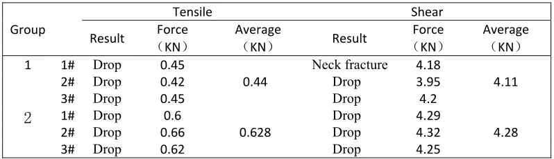
TABLE VIII. TENSILE AND SHEAR TEST RESULTS.
Group
Tensile Shear
Result (Force KN)
Average
(KN) Result
Force
(KN)
Average
(KN) 1 1# Drop 0.45
0.44
Neck fracture 4.18
4.11
2# Drop 0.42 Drop 3.95
3# Drop 0.45 Drop 4.2
2 1# Drop 0.6
0.628
Drop 4.29
4.28
2# Drop 0.66 Drop 4.32
3# Drop 0.62 Drop 4.25
CONCLUTIONS
The performance of clinching joint is influenced by the parameters of mould. ABAQUS is used as the grid analysis software. Several methods are used in simulation: fluid model for solving the simulation problem of material strong stage; ALE method for the mesh distortion adjustment to improve the precision; and parameterizing mould by using punch radius, die radius, depth of die, depth of die groove and width of die groove. Furthermore experiments with different parameter combination are conducted. Through comparing and analyzing the results of experiments and simulation, the response surface equation of self-locking value and neck thickness are established. The next step is to use genetic algorithm in optimization, and get the optimal solution of the die parameters in this experiment. Finally, the experiment result verifies the correctness and reliability of the simulation optimization that the tensile strength and shear strength of the optimized clinching joint are increased by 41.4% and 4.1%, respectively. This study provides a reference for the parametric processing of the die and the feasibility of multi-parameter optimization. In this paper the sheet thickness is not taken as a variable, which will be the further study of the intelligent optimization between the sheet thickness and mould parameters.
REFERENCES
1. Varis J.P. The suitability of round clinching tools for high strength structural steel [J]. Thin Walled Structures, 2002, 40(3): 225-238.
2. Varis J.P., Lepistö, J.. A simple testing-based procedure and simulation of the clinching process using finite element analysis for establishing clinching parameters, [J]. Thin Walled Structures, 2003, 41(8): 691-709.
4. Roux E., Bouchard, P.O.. Kriging metamodel, global optimization of clinching joining processes accounting for ductile damage, [J]. Journal of Materials Processing Technology, 2013, 213(7): 1038-1047.
5. M.M. Eshtayeh, Clinching process for joining dissimilar materials: state of the art [J]. Int J Adv Manuf Technol (2016) 82: 179–195.
6. Xiaocong He, Mechanical properties of extensible die clinched joints in titanium sheet materials, [J], Materials and Design 71 (2015) 26–35.
7. Guo X.N., Song J., Xu K. Remapping-free ALE-type kinetic method for flow computations, [J]. Journal of Computational Physics, 2009, 228(8): 3154-317.
8. Balawender T., Sadowski T., Golewski P. Numerical analysis and experiments of the clinch-bonded joint subjected to uniaxial tension [J]. Journal of Materials Processing Technology, 2012, 174(64): 270-272.
9. Pedreschi R., Sinha B.. Predicting the Shear Strength of Mechanical Clinching in Cold-Formed Steel Structures [J]. Journal of Materials in Civil Engineering, 2006, 18(3): 435-442 10. Yag˘cı S., Go¨g˘u¨s F. Response surface methodology for evaluation of physical and