2016 International Conference on Computer, Mechatronics and Electronic Engineering (CMEE 2016) ISBN: 978-1-60595-406-6
Study of a M/T Method of Variable Sampling Period and its
Implementation Based on STM32 MPUs
Yi-qing Luan
1,*, Peng Xiao
2, Shi-you Mu
1, Jin-long Zhao
2and Jun-tao Lv
31Shandong Electric Power Research Institute, Jinan, 250101, China 2Shandong Luneng Intelligence Technology CO., LTD, Jinan, 250101, China
3State Grid Shandong Electric Power Company, Jinan, 250000, China
*Corresponding author
Keywords: M/T method, Speed measurement, Optical incremental encoders, Based on STM32.
Abstract. In this paper, a new M/T method of variable sampling period is introduced for speed measurements by optical incremental encoders. In this method, we estimated the number of encoder pulses to count in next counting interval at the end of every sample period, so the sampling intervals were variable. Both encoder pulse and high frequency clock pulse were counted in the variable intervals and the counting of clock pulses begins and ends at the exact rising age of the encoder pulse. Through this method, the error is only one clock pulse which is much shorter than encoder pulse, which guarantees a more accurate speed measurement and rapid response of motor system.
Introduction
A servomechanism is an automatic device that uses error-sensing negative feedback to correct the performance of a mechanism or follow a process defined by its function. Most servos are rotary actuators which are widely used in robot control field. In servo control system applying rotary motors, the measurement of motor speed is an important loop and the measurement accuracy of motor speed has a great influence on the performance of the servo control system[1].
Many devices are commonly used in motor speed measurement such as hall sensors, tachometers, resolvers, tachogenerator and incremental photoelectric encoders which is used in this study[2]. A photoelectric encoder is an electro-mechanical device that converts the angular position or motion of a shaft to digital signal[3]. The incremental photoelectric encoder we used was produced by Maxon company and its model name is HEDL-9140. This encoder output 3 square wave pulse of A, B and Z, among which phase A and B can generate 500 counts per turn while phase Z outputs only one pulse signal per turn. Phase A and B are quadrature encoder pulse signals, by detecting the relation between them we can distinguish the positive or negative rotary direction of motors.
M/T Method
Encoder pulses
Clock pulses
…
Sample period
m1
m2
Ts
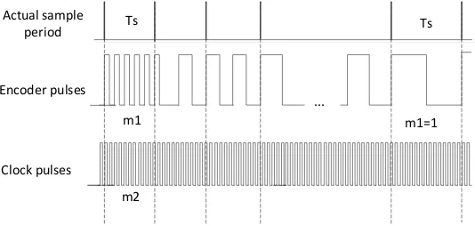
Figure 1. M/T method.
The motor speed can be given by Eq.1.
1 2
60 fclk m v
N m
(1)
where, fclk is the frequency of clock pulse and N is the encoder pulse number per turn of the motor. In the conventional M/T method, we need at least three timers to implement this, one of which is used to generate a sample period and one is used to count encoder pulses while the other one for clock pulses. As shown in Fig.1, we know that it is important to align the encoder pulse edge and the sample pulse edge to improve sampling accuracy, but it is difficult to achieve this.
M/T Method of Variable Sampling Period
As its name implies, this method has variable counting intervals. In this method, the ideal sampling period T is given by user while the actual sampling period Ts determined by the number of encoder pulses in a counting intervals. So only two timers are needed in this method for counting encoder pulses and clock pulses. In this case, Ts approximates T but may not equal T most of the time. To achieve this, we begin counting the clock pulses at the first rising edge of the encoder pulse m2 and finish at the end of the whole encoder cycle, as shown in Figure 2.
... m1
m2
Ts Ts
m1=1 Encoder pulses
Clock pulses Actual sample
period
Figure 2. M/T method of variable sampling period.
The motor speed is given by the same equation as Eq.1 in the M/T method. In order to make the actual sampling time Ts approaching the ideal sampling time T, we estimate the number of encoder pulses to count Nk1in next counting interval, according to the new speed we got this time (called
k
v ). Nk1 is given by Eq.2.
1
60 k k
v N T
N (2)
[image:2.595.158.445.70.197.2] [image:2.595.168.435.485.612.2]Implementation Based on STM32 MCUs
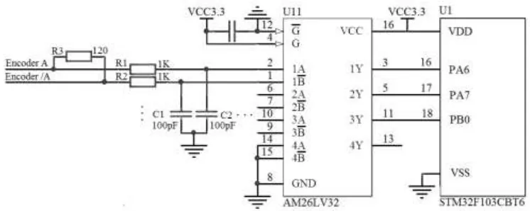
[image:3.595.109.482.173.322.2]In this study, a STM32F103CB microcontroller from STMicroelectronics is used to achieve the above purpose. STM32F103CB microcontroller has three general-purpose timers and one advanced timer, all of them have encoder interface with four frequency mode and could be operating at a 72 MHz frequency. The three-phase signal of incremental photoelectric encoder Input to the MCU pins of PA6, PA7 and PB0 through a differential line receiver IC AM26LV32. The interface circuit of the photoelectric encoder is shown as Figure 3.
Figure 3. Incremental photoelectric encoder interface circuit.
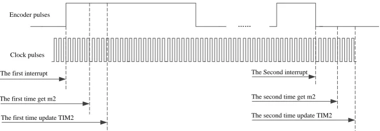
Two timers of TIM2 and TIM3 are used in this method. TIM2 is operating in up counting mode for recording the high-speed clock pulse number m1 and its operating frequency is 72 MHz. Since the counter of TIM2 is a 16-bit counter, it only record about a millisecond max, for the encoder with 500 slits, the maximum motor speed can be detected is about 33 rpm. To improve the detection range of motor speed, two variables tim2_cnts and tim2_overflow are used, where tim2_overflow is used for recording the number that the counter reaches the top value.
TIM3 is used to count encoder pulses, working in encoder interface mode, up counting and the counter is clocked at each valid edge of phase A and B. When the pulse count reaches the number given by Nk1, the timer will generate an overflowing interrupt and motor speed will be calculated by Eq.1 in the interrupt service program. Since when an overflowing interrupt occurs, the value of counter register TIM3_CNT has been changed to 0, we get m1 from the auto-reload register
TIM3_ARR. The core code of this method is as follows.
tim2_cnts = TIM2->CNT; TIM2->CNT = 0;
TIM2->CR1 |= 0x0001;
tim2_cnts += tim2_overflow<<16; //Get clock pulse number m2
tim2_overflow = 0;
tim3_cnts = TIM3->ARR+1; //Get encoder pulse number m1
rotate_direction =((TIM3->CR1)&(uint16_t)0x10)>>4;
new_speed= (float)tim3_cnts*72000000.0/(float)tim2_cnts; // Calculate the new speed tim3_arr = (new_speed>>12)+1; //Estimate the encoder pulse number to get next time
Error Analysis and Experiment
Encoder pulses
……
The first interrupt
The first time get m2
The Second interrupt Clock pulses
The first time update TIM2
The second time get m2
[image:4.595.115.488.69.198.2]The second time update TIM2
Figure 4. Timing diagram of this method.
[image:4.595.137.460.336.443.2]By generating pulses through the microcontroller pin to simulate an encoder and measuring the pulse frequency through the oscilloscope, we tested the measurement error of the new M/T method in the frequency range of 100 Hz to 100 KHz. In the test, speed is given by the encoder pulse frequency with unit [Hz], which is independent of encoder features. The test result is shown in Table 1. We also test the program efficiency by setting a microcontroller pin at the start of the program and reset it when program exits. According to our test, the update frequency of motor velocity is about 3 KHz and the execution time for each measure is 24 microsecond.
Table 1. Test result.
No. Given[Hz] Measurement[Hz] Oscilloscope[Hz] Error[%]
1 100 100 100 0
2 500 500 500 0
3 1000 1000 1000 0
4 5000 5002.8 5000 0.06 5 10000 10005.8 10000 0.06 6 25000 25016 25010 0.02 7 40000 39048.5 39920 2.18 8 50000 49038.8 49980 1.88 9 100000 96030 99890 3.86
According to the test results, when the encoder pulse frequency is less than 40 KHz (which is about 4800 RPM for our motor), we obtain a very small test error that is nearly zero. When the encoder pulse frequency is bigger than 40 KHz, the test error become bigger also, but it still in the acceptable range.
Summary
In this paper, a new method for incremental encoder-based motor speed measurement has been proposed and its implementation on a STM32F103CB microcontroller has been introduced. In this method, the counted encoder pulse number is auto changed every sample period according to the motor speed to guarantee high accuracy for a wide speed range. With this method, we obtain a more accurate speed measurement and rapid response than the conventional variable M/T method. According to our experiment, we got a very small speed error in the frequency range of 100 Hz to 100 KHz, which is 12 RPM to 12000 RPM for the motor in our system. So it can offer a more accurate speed feedback signal for the speed controller and improve the performance in a wide speed range for the numerical control system or servo system.
References
[1] Muhia A M, Nderu J N, Kihato P K, et al. Performance of Magnetostrictive Amorphous Wire Sensor in Motor Speed Measurement[J]. Innovative Systems Design & Engineering, 2012, 3(6).
[3] Xu-Dong F U, Ying F U, Bing X U. Photoelectric encoder for position detection[J]. Journal of Shenyang Electric Power Institute, 2002.
[4] T. Ohmae, T. Matsuda, K. Kamiyama, M. Tachikawa, in: A microprocessor-controlled high-accuracy wide-range speed regulator for motor drives, IEEE Trans. Ind. Electron., vol. IE-29, no.3, p. 207-221 (1982).
[5] Lilit Kovudhikulrungsri, Takafumi Koseki. in:Precise speed estimation from a low-resolution encoder by dual-sampling-rate observer, IEEE/ASME Transactions on Mechatronics, vol.11, no. 6, p.661-670 (2006).