2016 Joint International Conference on Artificial Intelligence and Computer Engineering (AICE 2016) and International Conference on Network and Communication Security (NCS 2016)
ISBN: 978-1-60595-362-5
Design of the Vision Positioning Grab Mobile Robot System
Zhi-Hua LIN
1,a, Xue-Liang PING
1,2,b,*1School of JUNYUAN, Jiangnan University, Wuxi, Jiangsu, China
2School of Mechanical Engineering, Jiangnan University, Wuxi, Jiangsu, China
a[email protected], b[email protected]
*Corresponding author
Keywords: Mobile Platform, Visual Capture, Image Processing, Vision Positioning, Automatic Positioning.
Abstract. A kind of vision positioning grab mobile robot control system based on Arduino is designed in order to realize the identification and grasp of the specific object. The system uses visual capture technology and image processing technology to locate the particular object, and transmit the position information which is already analyzed through SPI communication to the mobile platform based on STM32 and control mobile platform to realize automatically locating and tracking. When reaching the set position, control the robotic arm complete the grasp task. Experimental result shows that the physical prototype which built according to the vision positioning grab mobile robot system can automatically complete visual location and identification, mobile platform tracking and collision free travel and the grasp of the particular object.
Introduction
With the rapid development of the robots and the urgent demand of the manufacturing process, the mobile robot technology is more and more concerned by the society. The robot system composed of the sensor, the remote controller and the automatic control moving carrier has been developed rapidly [1].
Mobile robots are fit for working in the complex nonstructural environment, with highability about self-planning, self-organization and self-adaptation. Mobile robot has strong mobile function, and greater mobility and flexibility than the general robot. It can operate freely in a narrow or crowded work place, and can better control the robotic arm's operation posture and the operation accuracy. The mobile robot with vision positioning can better perceive and locate the target, complete the task quickly and accurately and enhance the efficiency of the work greatly [2].
In this paper, a control system of vision positioning grab mobile robot based on the Arduino is designed, and the design is divided into two parts: hardware design and software design. Using the camera to visual locating a particular object, analysis data and send them to the mobile platform and the robotic arm, so that they can automatically locating and tracking, and finally realize the grasp of the particular object.
System Hardware Design
System uses two wheel independent drive vehicle as the mobile robot platform [3], the STM32F103ZET6 chip of the 32 bit microprocessor based on the Cortex-M3 ARM core as the controller; the R04 – HC as the ultrasonic module and the NRF24L01 as the wireless module.
The working mode of the whole system is shown in Fig. 1, the upper computer connects the wireless module to the ARM processor through SPI, and the rocker ADC control module is initialized at the same time. The ARM processor can analyze and recognize the instructions on the LCD display, and send the instructions to the lower computer [4]. The upper computer can also communicate with the computer through the USART serial port.
The lower computer first initializes all the modules, and waits for the instructions from the upper computer. When the lower computer receives the grasp instruction, the camera first identifies the particular object and stores the position information at the same time. The lower computer turns into grasp mode, tracking automatically and achieving the obstacle avoidance by using ultrasonic sensor. When the tracking is done, control the robotic arm to complete the grasp.
USART Upper Computer NRF2401 wireless module ADC Joystick LCD display Lower Computer
AREXX 6 degrees of freedom robotic
arm
Pixy CmuCam 5 Camera
[image:2.612.230.384.202.365.2]Ultrasonic module
Figure 1. Working mode.
System Software Design
In the software design, all the tasks in the system are divided into different and independent subroutines. According to the performance index and technical requirements of the system, the subroutine can be divided into: Ultrasonic ranging, Wireless information transmission, Visual capture, Information processing, etc..
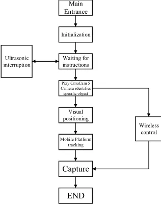
System Control Flow. After the initialization of the peripheral and the initialization of the platform’s function are completed, configure the lower computer into receiving mode and continuously collect instructions from the upper computer. When receiving the relevant instructions and data, enter the corresponding process, as shown in Fig. 2.
Main Entrance
Initialization
Waiting for instructions
Pixy CmuCam 5 Camera identifies specific object Visual positioning Mobile Platform tracking Capture END Wireless control Ultrasonic interruption
[image:2.612.226.384.521.723.2]The system adopts sequential execution in each subroutine. Once a subroutine is executed, the processor re allocates the tasks and data. In the subroutines: ultrasonic interruption calls DistanceCheck () function to measure and calculate, and the ultrasonic pulse duration information is stored in the uwave variable, waiting to be sent or read directly; wireless control function mainly achieves the communication between the upper computer and the lower computer by calling the NRF_TX_Mode () and NRF_RX_Mode () function; Visual positioning function mainly using the getblock () function to identify the area of a specific object (pixy.blocks[0].height * pixy.blocks[0].width) and then determining whether to reach the distance [5] , when the distance is close enough, the robotic arm will catch the specific object.
Ultrasonic Ranging. Ultrasonic sensor uses ultrasonic emission device to launch ultrasonic wave and according to the time difference of the ultrasonic wave to realize the distance measurement. It has the advantages of strong directivity, rapid detection, easy to implement real-time control and so on [6].
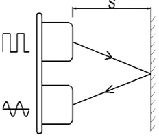
Mobile robot platform uses R04 - HC ultrasonic module, when performing the ultrasonic ranging subroutine, the ultrasonic emission device will launch 8 40kHz square waves automatically and check if there is a signal return. If there is a signal return, IO port ECHO will export a high electrical level and the duration of the high electrical level(ΔT) is the time difference of the ultrasonic wave from launch and return, the concrete principle is shown in Fig. 3.
After calculation of the formula (1), it is available to measure the distance S:
S= (ΔT*V)/2. (1)
[image:3.612.247.363.391.491.2]In the formula, V is the ultrasonic propagation speed, the propagation velocity of ultrasonic wave in air at room temperature is 340m/s.
Figure 3. Ultrasonic ranging schematic diagram.
The ultrasonic module uses the timer control, configure STM32 general timer 2 for counting and general timer 4 as the sampling period. Every second will enter a timer 4 interrupt, we use the UltrasonicWave_StartMeasure () function to monitor the length of time signal, the UltrasonicWave_CalculateTime () function to calculate the exact value, and stored the data in the variable UltrasonicWave_Distance, waiting to be used.
Wireless Information Transmission. Mobile robot platform uses NRF24L01 wireless module, and it works at 2.4 ~ 2.5 GHz band, with the automatic retransmission function, 6 data transmission channels, maximum wireless transmission rate for the 2mbits.
Visual Capture (take tennis as an example). Mobile robot platform uses CmuCam5 Pixy image processing module [7]. It is an open source image recognition sensor, supporting multi object and multi color recognition (the maximum support is 7 color). In addition, Pixy also supports a variety of communication methods, such as SPI, I2C etc., and it can dip in the Arduino control board directly. The imaging sensor It carries with the powerful hardware can coordinate with PC for tracking and analyze multi colors.
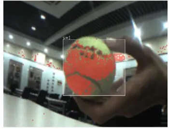
[image:4.612.228.403.170.303.2]We can use the function set signature of the PixyMon software to make the camera record the tennis image(shown in Fig. 4).
Figure 4. Successfully Catch the tennis.
Image processing. Record the color of the tennis (gray value) into Pixy [8], use getblocks[] function to get the tennis’s width, height, X coordinates and Y coordinates of the center point. Pixy captures the range of X values is 0 to 360, and the Y value is 200 to 0, and the position information can be observed through a serial port monitor (shown in Figure 5).
Figure 5. Location information.
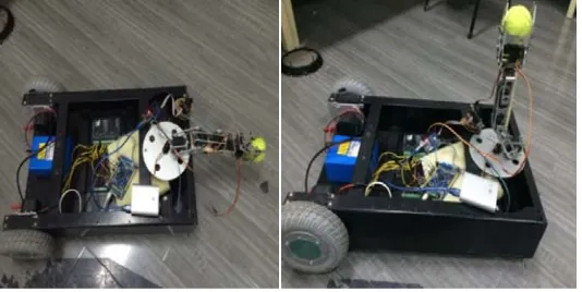
[image:4.612.186.431.394.530.2]the mobile platform stops moving forward, and turns into the robotic arm subroutine, the robotic arm grabs the tennis.
Figure 6. motion diagram.
Figure 7. Grab tennis schematic.
Experimental Test
Burn the program to the upper computer and mobile platform and open mobile robot platform power supply.
If the system is initialized successfully, the operator can see the System Init Success prompt on the LCD monitor.
When the mobile robot platform enters the grasp mode, the camera will do the visual processing according to the previously recorded image, and can automatically complete visual location and tracking. When the grasp is completed, the mobile robot platform will stop working, and send a stop signal to the upper compute. As shown in Fig. 8.
Figure 8. Experimental Test.
Conclusion and Prospect
[image:5.612.175.442.524.658.2]man-machine communication between mobile platform and operator become more flexible and convenient and the mobile platform can well adapt to the complex and unstructured industrial environment.
References
[1] Li Hong, The main method of path planning for autonomous mobile robot, J. China Electric Power Education. S1 (2010) 814 -816.
[2] Wang Liyan, Chen Ming, Survey of mobile robot navigation and localization and map building, J. New technologies and products. 17 (2011) 13.
[3] Lin Zhihua, Ping Xueliang, Design and control of Omni-directional mobile platform based on STM32, J. Electronic Measurement Technology. 1 (2016) 19-21.
[4] Wang Zhiling, Wen Kai,Chen Jie, Small mobile robot control system based on Android, J. Foreign Electronic Measurement Technology. 33 (2014) 4-7.
[5] S.Y.T. Lang, Yili Fu, Visual Measurement of Orientation Error for a Mobile Robot, J. IEEE. 6 (2000) 1344-1357.
[6] Zhang Li, Qin Haichun, Wang Wenbin, etc., Intelligent wheelchair positioning method based on ultrasonic and track reckoning fusion, J. Journal of Electronic Measurement and Instrument. 28 (2014) 62-68.
[7] R.V. Sharan, Suva, Fiji, G.C. Onwubolu, Automating the Process of Work-Piece Recognition and Location for a Pick-and-Place Robot in a SFMS, J. I.J. Image, Graphics and Signal Processing. 4 (2014) 9-17.
[8] Maria Pateraki, Haris Baltzakis, Panos Trahanias, Visual estimation of pointed targets for robot guidance via fusion of face pose and hand orientation, J. Computer Vision and Image Understanding. 120 (2014) 1-13.
[9] Yin-Tien Wang, Guan-Yu Lin, Improvement of speeded-up robust features for robot visual simultaneous localization and mapping, J. Robotica. 4 (2014) 533-549.
[10] Lv Lixin, Li Qing , Li Lu,etc.., Design of assembly robot based on PD motion control algorithm J, Journal of Chongqing University of Science and Technology, J. Natural Science Edition. 3 (2012).
[11] Romeo Tatsambon Fomena, Omar Tahri, Franc¸ois Chaumette, Distance-Based and Orientation-Based Visual Servoing From Three Points, J. IEEE. 2 (2011) 256-267.