2016 Joint International Conference on Artificial Intelligence and Computer Engineering (AICE 2016) and International Conference on Network and Communication Security (NCS 2016)
ISBN: 978-1-60595-362-5
Study on Influence on Sensitive of Thermosensitive
Element to Open Jet Gyroscope
Xing-Yuan CHANG
1,a,*, Lin-Hua PIAO
2, Lei DUAN
3,
Hao-Liang DONG
4,d1,2,3,4Sensors Technology Research Centre,
Beijing Information Technology Institute, Beijing, China
*Corresponding author
Keywords: Fluid-Solid Coupling, Open Jet Gyroscope, Sensitive Mechansim, Ther-mosensitive Element.
Abstract. This paper describes the effect mechansim of sensitive of thermosensitive element to open jet gyroscope. When different angular rate is applied, the distribution of airflow velocity at thermosensitive element is calculated by using fluid-solid coupling. The result shows that when angular rate about Z axis is applied, the distance between thermal resistance wires of d=0.6mm can decrease the influence of vortex inside of jet sensing cavity. Then, the temperature of thermal resistance wire is changing fast, which can increase the output voltage of Wheatstone Bridge and improve the sensitive of open jet gyroscope.
The jet gyroscope can be applied in rugged environment with the virtue of supporting high overload and low cost etc. [1]. Open jet gyroscope is miniature gyroscope that the structure is simpler. Thermal resistance wire is thermosensitive element of open jet gyroscope and the detection of angular rate is carried out by Wheatstone Bridge consist of thermosensitive element. When the gyroscope has the angular rate input, the airflow velocity of two symmetrical thermal resistance wire is different. With the increasing angular rate, the difference of airflow velocity is increasing at the mean time. Accordingly, this causes the changes of current crossing two thermal resistance wire. Furthermore, the output of Wheatstone Bridge is voltage corresponding to angular rate.
This paper calculates the flow field distribution of jet sensing cavity inside of open jet gyroscope when different angular are applied. Additional, It studies the difference of airflow velocity when there are different distances between two thermal resistance wires, which lays foundation for the set of thermosensitive element.
Structure Principle
Figure 1. Sensing structure profile of fluidic gyroscope.
Figure 2. Operational principle of open jet gyroscope.
Physical Model
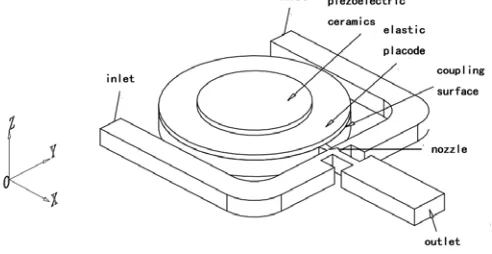
[image:2.612.187.433.481.608.2]As shown in figure 3, we simplify the jet gyroscope as two part, piezoelectric pump and the fluid-solid structure of jet cavity. Piezoelectric pump consist of piezoelectric ceramics and elastic placode. We load alternating voltage and zero to the upper surface of piezoelectric ceramics and downer surface of elastic placode, respectively. Then, coupling surface on the downer surface of elastic placode achieves the load transfer between fluid and solid. Additional, airflow in the channel is the air under oridinavx temperature and pressure. We assumed that pressure of inlet and outlet are standard atmospheric pressure.
Figure 3. Physical model profile of open jet gyroscope.
The Fluid-Solid Coupling Solution
Build up Piezoelectric Vibrator Model
(1) Select analysis type: the STRUCTURE analysis function has been selected in ANSYS.
(2) Define unit type: we choose the SOLID5 unit and the hexahedron SOLID45 unit as the structural unit of piezoelectric ceramics and elastic placode, respectively.
(3) Meshing: we divide the entirety to 2355 units, shown in figure 4.
[image:3.612.215.396.225.313.2](4) Applied load: We loaded sinusoidal voltage of 5V and 4.21kHz to the upper surface of piezoelectric ceramics. Frequency of sinusoidal voltage is a first order resonant frequency that can be get by modal analysis. The bulk compress of pump cavity is the biggest when first resonant is applied, because of which we can get the most fast fluidic bound. We loaded voltage of zero to the lower surface of elastic placode, where is coupling surface. Finally we can get the dat. document that using for coupling calculation.
Figure 4. Gridding of calculation area of piezoelectric vibrator.
Figure 5. Gridding of calculation area of fluid.
Build up Fluid Structure
(1) Select analysis type: the FLOTRAN CFD analysis function has been selected in ANSYS. (2) Define unit type: we selected FLUID42 unit as the fluid analysis unit.
(3) Meshing: we divide the entirety to 3875 units, shown in figure 5. Thus, there is cbd. Document that can be loaded to CFX.
(4) Applied load: We set up the coupling surface on the upper surface of pump cavity in the fluid area. In CFX, we set up density of fluid, viscosity coefficient, heat conductivity coefficient, temperature, intensity of pressure and the specific heat capacity is AIR. Intensity of pressure of inlet and outlet is standard atmospheric pressure. Finally, there is def. Document that using for coupling calculation.
Solving
[image:3.612.217.393.363.468.2]Calculated Results and Discussion
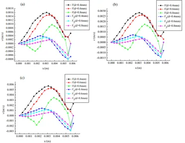
The differences between two sides airflow velocity are shown in figure 6, When gyroscope has the angular rate about Z axis ωz of 20°/s, 40°/s, 60°/s and the distances between two symmetrical
[image:4.612.121.493.172.461.2]thermal resistance wires are d=0.4mm, d=0.6mm, d=0.8mm, respectively. In this graph, X axis shows the distances of points on the section associated with Y axis to Y axis; Y axis shows the studied airflow velocity on the section; V shows the sum of jet velocity; Vx shows the velocity component on the Y axial direction.
Figure 6. Distribution of airflow (a) when ωz of 20°/s is applied (b) when ωz of 40°/s is applied (c) when ωz of 60°/s is applied.
When the angular rate rate of 20°/s is applied, the airflow velocity of points inside of jet sensing cavity changes, comparing to that at resting. The airflow velocity of two sides, at the same distance of center axis of jet sensing cavity, is different, which is not the balance state that has the same velocity at resting. From figure 4, for the differences of sum of velocity of two sides, it is smaller under the condition of d=0.8mm, when comparing to the condition of d=0.4mm, d=0.6mm. In addition, at area around outlet, the differences are almost equal when the distances of both 0.4mm and 0.6mm. But, at the outlet, the difference increased when the distance d=0.4mm because of velocity component on the Y axial direction Vy. Considering that velocity on Y axial is reason of causing vortex, which can seriously affect the thermal exchange between thermal resistance wires and thereby affect the sensitive of open jet gyroscope, when the angular rate of 20°/s and the distance of 0.6mm are applied, thermal resistance wires at two sides of center axial have bigger influence of airflow velocity, which can improve the differences of temperature on thermal resistance wires. Thus, the output voltage signal of Wheatstone Bridge is increasing, and thereby, promotes sensitive of open jet gyroscope.
Conclusion
(1)When the distance between two thermal resistance wires is fairly small, they affect each other because of the characteristic of thermal resistance wire, which can increase the error of sensing angular arguments of thermal resistance wires. Simultaneously, that can decrease the measurement range of jet gyroscope, and thereby, reduce the practicability.
(2)When the distance between two thermal resistance wires is fairly big, because the distribution of jet is funnel pattern based on diffusion principle at the jet spreading direction, the velocity of airflow reduces with the increasing distances between thermal resistance wire and center of jet, as well as between thermal resistance wire and nozzle.
(3)When the gyroscope has the angular rate about Z axis input, only when the distance between two symmetrical thermal resistance wire is d=0.6mm, can it reduces the influence of vortex inside of jet sensing cavity. Furthermore, it increases the changes of temperature on thermal resistance wire. Thus, it increases the output voltage of Wheatstone Bridge, and thereby, promotes the sensitive of open jet gyroscope.
Acknowledgement
This research was financially supported by:National Natural Science Foundation of China (60772012); Beijing Natural Science Fund Project & Beijing City Board of Education Science and technology key project (KZ201511232034); Key Laboratory of Beijing open projects funded project; engineering in the new century talents cultivation of Beijing funded projects; Modern Control Technology funded by Ministry of Education Key Laboratory. Graduate student innovation projects of Beijing Information Science and Technology University.
References
[1] Fuxue Zhang, Modern piezoelectric (Part ii) [M], BeiJing: Science Press, 2002.
[2 ] Linhua Piao, Bin Zhang, Jinduo Zhang, Fuxue Zhang, FEA of sensitive mechanism of piezoelectric fluidic angular rate sensor, Piezoelectric & Acoustooptics, J, 27 (3) 309-301.
[3] Linhua Piao, Yi Wang, Yujie Liu, Effect of Environmental Temperature on the Sensitivity of the Airflow Level angular rate Sensor, Electronic Components and Materials, J, 27 (2) 1-3.
[4] Kai Cheng, Guofu Yin, Research on several Modeling methods in ANSYS, Computer Application Technique, J, 32 (6) 39-40.