2017 International Conference on Electronic and Information Technology (ICEIT 2017) ISBN: 978-1-60595-526-1
Rational Modeling of Narrow Band Antenna by Vector Fitting
Han-Sheng WANG
1, Ming-Hui ZHANG
1,
Wei-Liang HE
1,a,*,
Lu TANG
2and Bing JIANG
31
School of Information Science and Engineering, Southeast University, Nanjing 211189, China
2
Institute of Radio Frequency and Optoelectronic Integrated Circuits, Southeast University, Nanjing 210096, China
3
State Key Laboratory of Mobile Communications, Southeast University, Nanjing 210096, China
a
*Corresponding author
Keywords: Rational modeling, Narrow band antenna, Vector fitting.
Abstract. This paper proposes a new methodology in rational modeling of narrow band antenna. Through the analysis for the measured Z-parameter of the antenna via vector fitting method (VFM), the rational fraction polynomial can fit the Z-parameter accurately. By comparing the basic models with the polynomial, the rational model of the antenna and parameters can be derived. The model has high accuracy in characterizing the antenna, and plays a guiding role in narrow band antenna design.
Introduction
Narrow band antenna is a new type of antenna, which is gradually developed in the last 30 years. Compared with the common microwave antenna, narrow band antenna has the advantages of miniaturization, ease of integration, good directivity, etc. It has been widely used in Terahertz research [1], Wireless Local Area Network (WLAN) research, Global Positioning System (GPS), etc.
In the design of the narrow band antenna, developing a rational model for the antenna is one of the most common and practical way to characterize the electromagnetic characteristics of the antenna [2]. In general, the rational model is closely related to the physics and geometry of the antenna, which can provide a good reference for the design of the antenna through simulating the parameters of the rational model [3]. There are two basic requirements to propose the rational model [4].The first one is the impedance requirement: the input impedance Zin and admittances Yin of the rational model should
be matched to those of the modeled antenna. The second is the radiated behavior requirement: the load resistor RL should be equal to the resistor of the antenna’s
radiation Rrad. In order to meet the requirements, the numerical curve fitting is one of
the most common ways to extract parameters in the development of the rational model [5]. However, the numerical fitting method has an assignable problem. It often has a large amount of computation and is difficult to converge and get stable solutions.
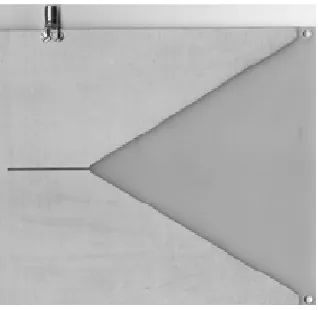
antenna, the reasonable rational model of narrow band antenna shown in Figure 1 can be established and all the model parameters can be extracted.
Figure 1. Photo of the narrow band antenna.
Vector Fitting Method
Vector fitting method (VFM) is widely used in power system modeling for its superior fitting performance with few iterations and sufficient reliability. Besides, VFM can not only fitting using real poles to get smooth curves, but also complex poles to get syntonic curves. The process of VFM mentioned in this paper can be described as follow.
Firstly, given z(s) as a frequency response of the rational function approximation in VF.
1
( )
=
= + +
−
∑
N k
k k
C
z s sh d
s a
(1)
Ck and ak are either real quantities or complex conjugate pairs, while h and d are real.
The parameters can be abstracted using LS (least square) method, however, ak lies in
denominator, make it a knotty nonlinear problem.
Then, use a rational function σ( )s act on z(s) to make it a rational function. σ( )s
and z s( ) were defined as the formula (2) and the formula (3).
N
k=1
( )= 1
σ +
−
∑
kk
D s
s a
(2)
( )=σ( ) z(s)
z s s (3) When discussed in high frequency, σ( )s can be approximately equal to 1. In that case,
the nonlinear problem (1) can be transformed into a linear problem (4).
N
k=1 1
( 1) ( )=
=
+ + +
− −
∑
∑
N
k k
k
k k
D C
z s d sh
s a s a
(4)
Alsoσ( ) ( )s z s and σ( )s have the same poles.
Supposed that initial iteration point ak is already known, for every measured point Sk, the linear
1 1 ( ) ( ) ( ) σ = = − = −
∏
∏
N n k N n k s d s s a (5)dk is a set of zeros of σ( )s . Also z(s) is written as the formula (6).
1 1 1 ( ( )) ( ) ( ) ( ) ( ) ( )
σ
σ
+ = = − = = −∏
∏
N n k N n kh s z
z s s
z s
s
s d
(6)
The poles of Z(S) become equal to the zeros of σ( )s .Thus, by calculating the zeros of
( )
σ s , a new set of poles for fitting the original function Z(S) is gotten. Now this is
become an iteration method in accordance with the poles of ( )
( ) n
z s and the zeros of ( 1)
( ) σ n+
s .
The iteration is conducted until σ( ) 1s − meet the precision requirement.
Whenσ( )s =1, z s( )=z(s). In that case, z s( )can approximately represent Z(S).
Rational Model of Narrow Band Antenna
In the paper, the following frequency response of the rational function approximation in VF is adopted to establish the rational model of narrow band antenna.
*
1 1 2
*
1 1
B B B
( )= + + +
− −
fit
Z s D
s A s A s (7) In(7),A1* AND A1,B1* AND B1ARE CONJUGATED.THE VALUES OF ALL PARAMETERS IN
(7) ARE STABLE IN APPROPRIATE PRECISION REQUIREMENT AFTERREPEATED ITERATIONS.
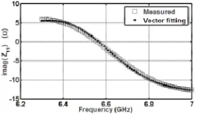
[image:3.612.231.375.473.557.2]THE VECTOR FITTING RESULTS OF Z-PARAMETER ARE SHOWN IN FIGURE 2 AND FIGURE 3.
Figure 2. The vector fitting results of real part of the Z-parameter.
[image:3.612.231.373.598.681.2]In order to facilitate the modeling of the antenna and the extraction of parameters in next step, the polynomials (7) need to be pretreated. Reduce first two fractions to a common, meanwhile, make some adjustments to eliminate negative numbers in the molecule. The Zfit(s) can be rewritten as the formula (8).
2 10 2 9 21
11
1.018 8.518 10 3.448 10
= 17.316
4.735 10 1.696 10
( ) fit
s s
s s s
Z s + × + × +
+ × + × (8)
[image:4.612.200.414.213.283.2]By analyzing the structure of (7) and (8), the rational model of narrow band antenna can be established as Figure 4 and its impedance expression can be computed in the polynomials (9).
Figure 4. The rational model of the narrow band antenna
2 1 2 1 1 2 1 1 2
2 1 2 1 2 1 2 1 2 1 1 2 1
3
R ( ) 1
Z( )
1 C
( )
( ) ( ) ( )
R R R
s s
R C R R
s
R R R s
s s
L R R R R C R R LC
R
+
+ +
=
+ + +
+ + +
+ + (9)
[image:4.612.210.401.414.511.2]According to the correspondence of (8) and (9), all model parameters can be extracted as shown in Table 1.
Table 1. Values of the parameters in the rational model.
Parameters Values
R1 -5.487 Ω
R2 0.859 Ω
R3 17.316 Ω
C1 2.9 pF
C2 2.9 pF
L 50.237 pH
Simulation and Validation
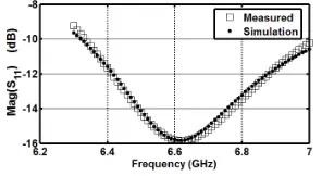
In order to verify the validity of this rational model for the narrow band antenna, the EM simulation of the rational model is compared with the measured S-parameter in both the magnitude and the phase respectively shown in the Figure 5 and Figure 6.
[image:4.612.228.376.597.678.2]Figure 6. Comparison of the phase of the measured S-parameter results and the EM simulation.
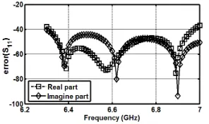
In the whole range of the frequency (from 6.3 to7 GHz), the rational model has high accuracy in characterizing the antenna. From the error plot shown in the Figure 7, the errors of both the real and imaginary parts are under the -30dB. The comparison results show that the rational model agree very well.
Figure 7. Comparison of errors of both real and image part of the measured S-parameter results and the theoretical model simulation.
Conclusions
This paper introduces a new rational model of the narrow band antenna with parameter extraction based on vector fitting. By using the VF method to fit the measured results, based on the rational fraction polynomial to describe the characteristics of the antenna, the rational model can be established and the related parameters can be extracted. This model has high accuracy in featuring the frequency-dependent characteristics of the narrow band antenna. The methodology of modeling can be effectively used in high-precision modeling of antenna.
Acknowledgement
This research was financially supported by the National Natural Science Foundation of China (No.61674036) and National Student Research Training Program (No. 201710286017).
References
[1] A. Schmid, J. Raasch, A. Kuzmin, S. Wuensch, and M. Siegel. Integrated Four-Pixel Narrow-Band Antenna Array for Picosecond THz Spectroscopy. IEEE Transactions on Applied Superconductivity. 26 (2016) 1-5.
[image:5.612.229.377.248.336.2][3] G. DeJean, M.M. Tentzeris. Modeling and Optimization of Circularly-Polarized Patch Antennas Using the Lumped Element Equivalent Circuit Approach. IEEE Antennas and Propagation Society International Symposium (2004).
[4] M. Mamdouh, Osama M. Haraz, Elsayed Esam M. Khaled. Modified Rational Function Modeling Technique for Printed Monopole Antenna for UWB Applications. IEEE Antennas and Propagation Society International Symposium (2013).
[5] N.G. Alexopoulos, Shih-Chang Wu. Frequency-Independent Equivalent Circuit Modelfor Microstrip Open-End and Gap Discontinuities. IEEE Transactions on Microwave Theory and Techniques. 42(7) (1994) 1268-1272.
[6] B. Gustavsen, A. Semlyen. Rational approximation of frequency domain responses by vector fitting. IEEE Transactions on Power Delivery. 14(3) (1999) 1052-1061.