Systems Reference Library
Input/Output Control System (on Tape)
Specifications and Operating Procedures
IBM 1401 and 1460
Program NI:.Jmber 1401 -10 -065
This publication describes the programming required to use lacs to control the input/output of data from card reader, card punch, printer, and tape files. The lacs descriptive entries (DlaCS and DTF) and macro instructions are explained in detail. The types of data records and tape labels handled by lacs "are defined. Also, two sections are included that should be espe-cially useful to experienced programmers: (1) Sum-maries - briefly lists storage-area considerations, macro instructions, and processing-overlap considerations; (2) Program Operation - describes lacs library routines, labels, halts, and error indications.
lacs is a supplement to the 1401 Autocoder program,
and the reader should be familiar with the program
described in Autocoder (on Tape) Specifications for
IBM 1401 and 1460, Form C24-1434.
Fourth Edition
This is a reprint of C24-1462-2 incorporating changes released in the following Tech-nical Newsletter:
Form Number
N24-0286
Pages Affected
7, 8, 9, 10, 11, 12, 12.1, 25, 26, 28, 29, 33, and 34
December 23, 1964
Significant changes or additions to the specifications contained in this publication will be reported in subsequent revisions or Technical Newsletters.
Requests for copies of IBM publications should be made to your IBM representative or to the IBM branch office serving your locality.
Address comments concerning this manual to: IBM Corporation, Programming Publica-tions, Dept. 425, Rochester, Minn. 55901.
Contents
Specifications .... ... ... 5
General Description ... ... 5
Processing Overlap Special Feature ... ... ... 6
Data Records... ... ... ... ... ... 7
Record Types and Storage Areas ... ... 7
Unblocked Records ... "... 7
Blocked Records ... "... 7
Control l'otals ... "... 10
Record Input and Output ... 10
GET Macro ... "... 10
PUT Macro ... ,... 13
RELSE Macro ... "... 17
SPACE/SKIP Macro ... ,... 17
Tape Labels ... 18
Standard Header Label ... "... 18
Standard Trailer Label ... "... 19
Label C)peration . ... ... ... ... 20
File Opening and Closing .. ... ... ... ... 22
OPEN Macro ... "... ... 22
CLOSE Macro ... "... 23
End-of-Reel for Multi-Reel Files ... "... 24
FEORL Macro ... "... 25
RDLIN Macro ... "... 25
DCLOS Macro ... "... 26
Descriptive Entries ... "... 27
DIOCS Entry ... "... 27
DTF Entry ... "... 29
Summaries ... "... 35
Core-Storage Areas ... 35
Macro Instructions ... "... 35
Processing Overlap Special Feature ... 35
Operating Procedures ... "... 38
IOCS Library Routines ... ... ... 38
Source Program ... "... 38
Object Program ... ... 39
The IBM 1401 and 1460 Input/Output Control System
eliminates the need for detailed programming of standardized input and output routines. IOCS requires descriptive entries and macro instructions in addition
to those used by the Autocoder program. With these,
the user has access to routines for reading and writ-ing, blocking and deblockwrit-ing, file labelwrit-ing, and error checking.
IOCS library routines are selected and tailored
auto-matically by the Autocoder processor to satisfy the
par-ticular requirements of each job. Autocoder generates
the minimum number of instructions needed according to the detailed information the user supplies in the de-scriptive entries.
Although primarily concerned with magnetic-tape
flIes, IOCS also applies to unit-record files in the IBM
1402 Card Read-Punch and to continuous forms
pre·-pared by the IBM 1403 and 1404 Printers.
The IBM 1401 system used to assemble programs
with IOCS must have at least:
• 4,000 positions of core storage
• Four IBM 729 II, 729 IV, 729 V, or 7330 Magnetic Tape Units • IBM 1~l03, Model 2, or 1404 Printer
• IBM 1402 Card Read-Punch • Advanced-Programming feature • High-Low-Equal Compare feature
• Sense switches (Not required for assembly from a source pro·· gram card deck, but necessary for all other Autocoder oper-ations.)
The IBM 1460 system used to assemble programs
with IOCS must have at least:
• 8,000 positions of core storage
• Four IIlM 729 II, 729 IV, 729 v, 729 VI, or 7330 Magnetic Tape Units
• IBM 1403 Printer, Model 2 • IBM 1402 Card Read-Punch
• Indexing-and-Store-Address-Register feature
• Sense switches (Not required for assembly from a source-program card deck, but necessary for all other Autocoder operations.)
The resultant object program can be used in any IBM
1401 system equipped with the advanced programming
and high-low-equal compare features or in any IBM
1460 system equipped with the indexing-and-stoaddress-register feature. Sense switches are also
re-quired if tape scanning will be performed (see DIOGS
Readerror ).
Specifications
General Description
The IOCS descriptive entries and macro instructions
are punched in Autocoder cards and assembled with
the source program.
The descriptive entry cards are inserted immediately
behind the Autocoder JOB and CTL cards, and ahead
of the user's source program. They describe the input/ output files used in the program and consist of two types· of entries:
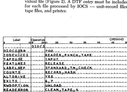
DIOeS --"Descriptive
lacs"
that describes generally the ma-chine configuration and the files used in the program (Figure 1).DTF -"Define The File" that describes, in detail, an indi-vidual file (Figure 2). A DTF entry must be included for each file processed by
lacs -
unit-record files, tape files, and printer. [image:5.618.335.580.306.484.2] [image:5.618.338.577.529.695.2]OPERAND 40 45 50
Figure 1. Sample DIOCS Entry
OPERAND
35 40 40 00
~~~~~~~~~~~~~ • • • • • • • I • • • • • •
~~~~~~~~~~~~.LI I I I I I • I • I ' , , • , I • , , ,
o L,L.,.6,2.0.7.4,.O.Jo. .. . . , . . ~~~~~~~~~~~~L' , . . . " I • •
Figure 2. Sample DTF Entry
Each DIOCS and DTF entry consists of a set of cards: a header card followed by several detail entry cards. The number of detail cards is governed by the factors that must be specified for a particular job.
These entries are explained in detail under Descriptive
Entries.
The macro instructions are entered in the source program whenever an input or output record is to be read or written. They provide linkage to the laCS library routines that read, write, block, deblock, and check records without further programming on the part of the user. Four basic operations are:
GET -moves a record from a file (tape or unit record) to an input or work area where it can be processed.
PUT -moves a record from an output or work area to a me (tape, unit-record, or printer).
OPEN -activates any file for processing, and checks or writes IBM standard header labels in tape files.
CLOSE -deactivates any file after processing is completed, and writes IBM standard trailer labels in tape meso Stand-ard input trailers are automatically checked imme-diately before the CLOSE.
Because IBM standard header and trailer labels are
processed automatically by laCS, it is to the user's ad-vantage to include them whenever possible. However, tape records with no header or trailer labels or with nonstandard labels can be processed. In this case, the user must write the program instructions to process his labels.
Other macro instructions used by laCS are: RELSE (release), FEORL (Forced End-of-Reel), DCLOS (Dump-Close), and RDLIN (Read Label Information).
6
Processing Overlap Special Feature
When this special feature is installed in an IBM 1401
or 1460 Data Processing System, records can be read,
written, and punched in the overlap mode by laCS.
This feature provides a reduction in over-all job time by efficient use of the high-speed processing and input! output capabilities of the 1401 and 1460. It is described
in detail in Special Features for IBM 1401 and 1460,
Form A24-3071.
Whenever this feature is used in conjunction with laCS, all input and output operations must be handled by laCS. The special programming and timing con-siderations of overlap are completely absorbed by laCS. Therefore, throughout his program, the user considers the records as being read or written in the
non-overlap mode. To provide for this, he specifies an
overlap operation in the DIOCS entry (FEATURES). lIe must also plan for this feature in the specifications of certain DTF entries and in the allocation of input/ output and work areas in storage for certain types of records. To gain the greatest time saving advantage of this feature, two input/output areas should be al-lotted when tape records are processed. Card records require a work area, and they cannot utilize the read release or punch release special feature. Cards in an input card file cannot be selected. All cards in the card reader stack in the normal pocket. For printer opera-tions, an additional macro instruction (SPACE/SKIP) is provided.
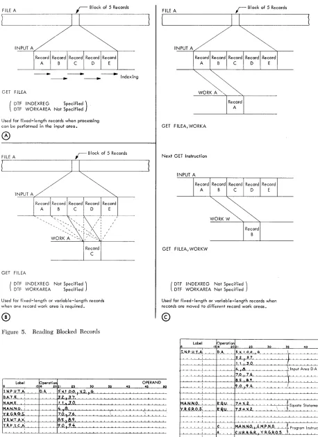
Record Types and Storage Areas
The IBM tape laCS processes records that are blocked
or unblocked and fixed-length or variable-length. Al-though all the records in a given file must be the same type, laCS can process several different-type files in the same operation. The four different combinations of
blocking and length are illustrated in the Schematic of
Record Types and Input Areas (Figure 3). For each combination, the schematic illustrates an input area,
several records read in, and the Autocoder DA
state-ment for the area. The labels containing the letters DTF refer to the corresponding DTF entry specifi-cations.
Whenever laCS controls the input/output of any
records, a record-mark code may be included only to
indicate the end of a record. It must not be used for
any other purpose. Also, because laCS requires
stor-age positions 90, 91, 95, and 96 when clearing the index registers, these positions must not be used by the programmer.
Unblock:ed
RecordsUnblocked records (Figure 3A, B) are read in, or writ-ten, one record at a time. This record type includes tape records, card input and output files, and printer operations.
Input/Output Areas
Each input/output storage area allotted for these rec-ords should be equivalent in length to the size of a single record. In the case of variable-length records, the area must provide for the largest record.
For tape records, the input/output areas must be defined by DA statements and a group-mark with word-mark must follow the area. The label (symbolic address) of the DA statement must be included in the DTF entries (IOAREAS). Because unblocked records (with one input area specified) are normally processed in the input area and reference must be made to in-dividual fields, word marks must be provided to define these fields, as in any 1401 or 1460 operation. The fields can be labeled and defined with high-order word marks by the DA statement. Or, if the tape contains word marks, they can be inserted by reading the tape record in the load mode.
Data Records
When laCS is to check the length of fixed-length in-put tape records (as specified by the DTF WLRADDR entry), one extra position must be ,allotted in the input
area, for laCS use. For example, if 100-character
rec-ords are to be processed, the DA statement for the input area must specify 101 positions. After a record is read in from tape, the extra position is located between the data record and the group-mark with word-mark position. When a correct -length record has been read, this position contains a group mark that was generated
when the tape interrecord gap was sensed. If a wrong:..
length record was read, this position may contain any character other than a group mark.
When an unblocked variable-length record is read in, laCS automatically inserts a record mark immedi-ately following the record in the input area. This re-places the group mark.
Unblocked tape records processed in the overlap
mode may be processed in a work area, or in the input/output area if no work area is specified. When two input/output areas are specified (DTF 10AREAS), however, the records can be processed in these areas only if indexing is also DTF -specified.
Because card-read, card-punch, and printer input/ output areas are fixed, they need not be defined or included in the DTF entries.
Work Areas
Generally, unblocked records (with one input/output area specified) do not require record work areas, as blocked records do, because fields can be readily
de-fined and used directly in the input/output area. If
a work area is desired, however, it must be defined by a DA statement. In this case the individual fields are labeled and defined by high-order word marks in this work area, rather than in the input/output areas. The label of the work area DA statement may be included in the DTF entry (WORKAREA) or referred to in the GET or PUT macro instructions.
The work area must be followed by a record mark
or a group-mark with word-mark, if it is used for a
fixed-length unblocked record that does not contain a record mark as its last character. Whenever laCS is to
move an unblocked variable-length record to or from
a work area, that record must contain a record mark
as its last character.
5 6
o 0
Input Area rl---0~1-_$-f1 (501601)
-L
DTF IOAREASDTF SIZEREC
All records read into specified Input Area (501-600) DA Statement:
Label DA 1XlOO,G 1,1
Fields defined as needed for the program
(3)
UNBLOCKED FIXED-LENGTH RECORDS (Form 1)5 0 Input Area 11
(501-1001) _
I-L
D T F IOAREAS I ..Record A I
Records ,
*: ,
~DTF----i
r----SIZEREC -I
DA Statement: Label DA 5X100,G
1,1
Record B
Fields defined as needed for the program
©
BLOCKED FIXED-LENGTH RECORDS (Form 2)
I-I
, , *' ,
Input Area (501-601)
5
o
I~
L
DTFIOAREAS
Records B , : : i _ _ _ _ -->:---'''''--': {
A:
C,::! ____________________________ ~:~~:
Area allotted for largest record DA Statement:
Label DA 1X100,G 1,1
®
UNBLOCKED VARIABLE-LENGTH RECORDS (Form 3).l _ _ _ _ _ _ _ _ _ _ _ _ _ _ _
1-
1-DTF BLOCKSIZE
Record C
:
*: ,
---~
~1
!*i}
,Record D Record E
1
5 0
o 0
Input Area r1 ___________________________________________________________ 0 +~_*I
(5011001)
-L
DTFIOAREAS
I
..
D T FBLOCKSIZE
Block of Records Read In
I Record A I
I I
I I
IRLI
I
:BL: *1
t
Record B
lui
t
D T F _ _--'~
_ _ _ _ _ _ _ _ _ _J
}Block of 4 Records Read In
SIZEREC
Records : : Record A : Record B· l Record C : Record D i Record E :
I}
:Bq IRL/ *: IRLI .jol IRLI ",: IRd *1 IRLI I
*
I Block of~~~~tL---~~I--~~tL---~L' --~~,~---~~I--~~J~--~I--~~J7---~t~I~-1 ~e~~c~~ds
~ _ _ _ _ _ _ ~_~ _ _ _ _ _ DTF _ _ _ _ _ _ _ _ _ _ ~ _ _ ~
I Record A I
I I
IRL/ :Bq
t
Area a Iloted for largest block DA Statement:Label DA 1X500,G 1,1
SIZEREC
I
I Record B I Record C
I
*:
IRd*:
IRdD
~
F _ _ _ _ _ _ _ _ _J
SIZERECBlock length (BL) - first field(4digits) of each block Record length (RL) - in same three positions within each record
@
BLOCKED VARIABLE-LENGTH RECORDS (Form 4)Figure 3. Schematic of Record Types and Input Areas
8
} Block of
[image:8.618.48.473.65.703.2]Card files that use the Read Release or Punch
Re-lease special feature, or that are processed in the
over-lap mode, require the use of a work area. All card output files require a work area.
Blocked
RecordsWhen blocked records are handled, two or more rec-ords at a time are read in from tape, or written on tape. The number of records in a block depends on the size of the records and the amount of storage that can be reserved for the block. The programmer must predeter-mine the record and block sizes and specify these in the proper DTF entries (SIZEREC and BLOCKSIZE). All records within a block may be the same length (fixed-length), or they may differ (variable-length). This affects the specifications written in the DTF en-tries (SIZEREC) and in the input, output, and work area DA statements.
When a block of records has been read, each record within the block, and the individual fields of data in that record, must be made available for processing ac-cording to the requirements of the job. With proper specifications, lacs can automatically read the block of records and locate the individual record.
When fixed-length records (Figure 3C) are proc-essed, the individual records and fields can be located by lacs control in either of two ways:
1. by using the indexing feature to step over to the beginning of each record in the input area.
2. by moving each record, one at a time, to a work area.
One method or the other, but not both, can be speci-fied. Therefore, in planning a job for fixed-length blocked records, the programmer must first determine whether he will process records directly in the input area or move them to one or more work areas for proc-essing. For example, will he identify a control field, such as a part number, in the input area and compare it to another number, or win he move the whole record to a work area and then identify the individual con-' trol field within that area. The advisability of using work areas for fixed-length blocked records is affected by the complexities of the user's program to process data for the particular job being planned. Such factors as the amount of core storage used for the job and the index registers required fo.r other functions must be considered. The laCS routines for the input/output of data handle one method as readily as the other.
Also, the programmer must determine if he will use
work areas for fixed-length output records, or if he will
build them directly in the output area.
When variable-length blocked records (Figure 3D)
are read, one or more work areas must be used.
Index-ing cannot be used to locate the individual records
and fields. When variable-length blocked records are to be written, however, either work areas or the DTF entry V ARBUILD can be used to build the blocks.
Requirements of Blocked Records
Several basic requirements of the records themselves must be met, to handle blocked records automatically by laCS:
l. Each record in every block must contain a record
mark as its last character. Therefore, the user must provide record marks in any records that will even-tually be read or written by laCS routines.
2. Fixed-length records must be padded so that all blocks are the same length. When output tape rec-ords are created by laCS, they are automatically padded with blanks unless the user specifies some other character in the DTF entries (PADDING). Padded records are included in record counts and
hash totals when these are specified (see Control
Totals).
3. For variable-length records, a block-length field must be included in each block, and a record-length field in each record (see Figure 3D).
Block length is a 4-position field and must always be recorded in the first four positions of the block.
As the name implies, it contains the total number of
characters in the block, including itself and record
marks. It is used by laCS for a wrong-length-record
check. The units position of the field must contain AB bits. When output tape records are created by laCS, this count and the AB bits are generated automatically.
Record length is a 3-position field and must be located in the same positions within each record in the file. It contains the total number of characters in the record, including itself and the record mark, and is used to modify addresses. For this purpose, the location of the low-order position within the record must be specified in the DTF entries (SIZEREC). For example, the 15th position is specified if the record-length field is located in positions 13, 14, and 15 in each record. Furthermore, the high-order stor-age position of the record-length field must contain a word mark in the storage area referred to auto-matically by the laCS routines. That is, the word mark must be in the work area whenever the work area is specified by the DTF entries (WORKAREA). When the work area is not DTF -specified, the word mark for this field must be in the input/output area. When output tape records are created, the pro-grammer must develop the length of the record to be entered in this field. Unlike block-length, this is not developed automatically by laCS routines.
Input Area
This area is equivalent in length to the size of the block of records. In the case of variable-length records, the allotted area must provide for the largest block. The area must be defined by a DA statement and followed by a group-mark with word-mark. The label of this DA statement must be included in the DTF entry (IOAREAS). The size of the input area (including the
4-position block-length field, if any) must be specified
in the DTF entry (BLOCKSIZE). This does not
in-clude the group-mark with word-mark position or the
extra position for record-length checking if that is
spec-ified in the DTF entry (WLRADDR).
When fixed-length records are processed in the input area (indexing specified) and reference must be made to individual fields, word marks must be' provided to define these fields, as in any 1401 or 1460 operation. The fields can be labelled and defined with high-order
word marks by the DA statement. Or, if the tape
con-tains word marks, they can be inserted by reading the tape record in the load mode. The index register used for this operation is specified in the DTF entries
(IN-DEX REG). It must also be specified in the DA
state-ment if records are processed in the non-overlap mode.
If they are processed in the overlap mode, the index
register must be omitted from the DA statement.
When variable-length records are processed and the work area is not specified in the DTF entry (WORK-AREA), the record-length fields must be defined with high-order word marks in the input area. This cannot be accomplished by the DA statement. Therefore, the word marks must be entered either by loading a tape record that contains the word marks, or by program-ming to insert the word marks in the proper positions after the block of records has been read in.
If blocked records are processed in the overlap
mode, two input areas may be specified in the DTF entry (IOAREAS) and defined by DA statements.
When 10CS is to check the length of a block of either fixed- or variable-length records (as specified by the DTF WLRADDR entry), one extra position must
be allotted in the input area. For example, if blocks
of five 100-character records are handled, 501 positions must be allotted, followed by a group-mark with word-mark. This can be specified by two DA statements for the area:
LABEL
10
DA 5X100 1,1
DA 1X1,G
} Field Definitions
After the block of records is read in from tape (fixed-length records or maximum-size variable-(fixed-length rec-ords), the extra position is located between the last data record and the group-mark with word-mark posi. tion. When a correct-length record has been read, this position contains a group mark that was generated
when the tape interrecord gap was sensed. If a
wrong-length record was read, this position may contain any character other than a group mark.
Output Area
The same principles as described for blocked-record input areas apply to output areas. In addition, consid-eration must be given to the recording of record marks. Because newly developed records are written via the output area, record marks must be provided in this area. They can be specified in the output area DA state· ment for fixed-length records. For variable-length rec-ords, however, the locations of the record marks cannot be predetermined. Therefore the programmer must in-clude program steps to insert a record mark immedi-ately after each record.
Work Area
This area is equivalent in length to the size of an indi-vidual record. For variable-length records, the area must provide for the largest record. Each work area must be defined by a DA statement and followed by a group-mark with word-mark. The label of this DA statement must be included in the DTF entry (WORK-AREA) or referred to in the GET or PUT macro in-structions. Because the work area is used for processing records, the DA statement should also label and define the individual fields with high-order word marks.
Control Totals
The 10CS routines can provide three control totals for
tape records with IBM standard labels: block count,
record count, and hash total. These totals are accumu-lated during the run and may be recorded on (output tape) or checked against (input tape) the trailer label, according to the user's specifications. A block count is always taken, and it is checked or written when standard-label operation is specified. For unblocked records, this is the same as the record count. The
rec-ord count and hash total are taken only if specified in
the DTF entries (TOTALS). If a discrepancy is de·
tected in anyone of these totals when an input trailer is checked by IOCS (see DTF TOTALS), a pro-grammed halt occurs.
specified in the DTF entries (TOTALS), and the field must be defined by a high-order word mark in the stor-age area referred to automatically by the IOCS rou-tines. That is, the word mark must be in the work area whenever the work area is specified by the DTF entries (WORKAREA). When a work area is not DTF-speci-fled, the word mark for this field must be in the input/ output area. The hash-total field can have a maximum of ten characters.
The record count and/or hash total may also be spec-ified for tapes with nonstandard labels. In this case they are accumulated automatically, but the user must pro-gram to check (input) or write (output) them.
Record Input and Oujtput
Once the programmer has determined the types of rec-ords to be handled and has planned the input, output, and work areas for his job, he writes only one instruc-tion each time the program calls for a rccord to be read, written, or punched. For these operations, IOCS makes two macro instructions (GET and PUT) available to the programmer. Two others (RELSE and SPACE) are provided for special conditions.
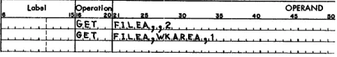
GET Melero
This instruction locates the next single record for proc-essing, and it can be written in either of two basic forms (Figure 4). In both forms, the term FILEA rep-resents the symbolic name of the file assigned in the DTF entry. The term WOHKA, in the second form, represents a work area used for the file and labelled in the DA statement. The form of the GET macro to use, and the specific functions performed, are determined by the types of records being handled and by the proc-essing plans specified in the file descriptive entries (DIOCS and DTF).
Blocked Fixed-Length Records
PROCESSING IN THE INPUT AREA
Whenever records are to be processed in the input area, the first form of the GET macro (GET FILEA) is used.
F
Label ,sreperati~121 25 30 35 40 O!ERAND 00, ,
-==+=_~_ G-bL~ ~~A, "_-'--C--'--'-~~L-~-'-'--~ __ L_L..L_ " __ L ' '-~ GET F'l L. E A , :W:O R K.A . . •. I • • • • • • • _ ' ' -~--~~-~~--'~~~ ~~~~- .
--'---'-~'---'---'--'-Figure 4. GET Macro Instruction
Blocked fixed-length records can be processed in the
input area, only if indexing is specified in the DTF
en-tries (INDEXREG). In this operation (Figure 5A), the first GET instruction causes a block of records to be read from tape to the input area, and it initializes the index register so that reference can be made to the first record in the block. Subsequent GET instructions increment the index register, and successive records can be processed. After all rccords in the block have been processed; the next GET again reads a block of records and initializes the index register.
When records are processed in the non-overlap mode, the particular index register specified in the DTF entry should be included in the input area DA statement. Also, the individual fields should be labelled in the DA statement, for reference throughout the pro-gram (Figure 6).
When records are processed with indexing in the
overlap mode, however, two basic changes must be
made in the DA statement for the input area (Figure 7, relate to Figure 6):
1. Field labelling must be omitted. 2. The index register must be omitted.
To assign labels to fields set up in the DA statement, the user must equate these labels to one-less-than the actual positions of the fields within the record. This is necessary because, with overlap, the index register al-ways contains the address of the high-order position of the record to be processed. Indexing must be indicated either in the equate statements, as shown, or in the in-dividual instructions throughout the program.
PROCESSING IN WORK AREAS
The first form of the GET macro (GET FILEA) is used whenever all records in an input file are to be processed in the same work area. For this, the label of the work area must be included in the DTF entries, and index-ing must be omitted.
The second form of the GET macro (GET FILEA, WORKA) is used whenever records are to be processed
in different work areas. It specifies the work area
re-quired for each separate record. It may be
advanta-geous to set up two work areas, for example; and to specify each area in alternate GET instructions. This would permit the programmer to compare each record with the preceding one, for a control change. When-ever work areas are to be specified in GET instructions, both indexing and a work area specification must be omitted from the DTF entries.
FILE A
- _ - - - - . . - - . Indexing
GET FILEA
( DTF WORKAREA Not Specified DTF INDEXREG Specified)
Used for fixed-length records when processing can be performed in the input area.
0)
FILE A
r
Block of 5 RecordsINPUT A
GET FILEA
Record A
Record C
( DTF INDEXREG Not Specified) DTF WORKAREA Specified
Used for fixed-length or variable-length records when one record work area is required.
®
Figure 5. Reading Blocked Records
Label 15~perati ~121
~ 25 30
1 NI' VT A, O.A. ,"1 00 .'i2. G
DAT E , 13~i.3.7.
NA.M E f 1 .• 30
MAN.N.O. 14 ... 8.
'Y.ltG,~O.S: 70 76
Y.R. 'WT A )(' 55.S.Il
YR"l~~~ 1'1.0 .• Cf.'t.
35 40
!
.
-'-,
.
OPERAND
45
\
FILE A
r
Block of 5 RecordsWORK A
GET F ILEA, WORKA
Next GET Instruction
GET FILEA, WORKW
( DTF INDEXREG Not Specified) DTF WORKAREA Not Specified
Used for fixed-length or variable-length records when records are moved to different record work areas.
©
Label Operation
1516 2021 25 30 35
OPERAND
40 45 50
t",.,I,Jl~\lJ.iAl,~ D A 5.J!.~LM.L'iG"_L-L~~_~~~~~'--L~~~ .. .:..-'--i'-'
'~L- ' 3 2.L}'-UJ.,~~-'---'---'-t'--'-"~-'-.I.-'---'--.i~-'--'-'--,-"-'
~l!
~~ 1130
~~~"_~~.-'--'-. ~~~., .. ~-'--'--.-L~,+-Input Area D A Statement---'-i
~-,--~~~~~~7~O,~~7~6~-,--~-,--,---,~~~-,---,~-,--,-,--~-,-~~~
la.s
8'
r-'-~~-'--'-'--~-+-~--'---"'-l-'Il-"O",.L}-) cLCf.u4'-'--'-'---'--'--L-'.L,--'--L ~--'--.LI ..L' --"L...L.-'--'---'--'--'--'--'----'----'--''--'
f-'-'~~~~~'~~-'--'--'--i...L.-'--~~~-'--'--'--.L..L-'--L-.LJ
,
.
, ---1.._ [image:12.612.46.504.63.692.2] [image:12.612.305.545.547.697.2]I I I I
Figure 6. DA Statement for Indexed Records, Non-Overlap
Mode. Figure 7. Indexed Records, Overlap Mode
the next individual record from the input area to the work area, until all records in the block have been proc-essed. Then a new block is automatically rcad in from tape, and the operation is repeated.
\Vork areas spccificd for input files may also be spec-ified for corresponding output files.
The principle of specifying the work area in the GET
instruction is also used when an output area is to be
treated as a work area. When the output records are
blocked in this operation, indexing must be specified in
the DTF entry for the output area. If records are
proc-essed in the non-overlap mode, the index register is
in-cluded in the DA statement for the output area, and the GET macro is written with the label of the output
area in the operand field (Figure 8). If records are
proc-essed in the overlap mode, however, the index register
cannot be specified in the output area DA statement, and must be included in each GET instruction. Instead of cntering the label of the output area in the operand field, thc output area is indicated by "0
+
Xn" (zero+
the number of the index register; Figure 9). Thisis necessary because, with overlap, the index regis-ter always contains the address of the high-order posi-tion of the record to be processed. The DA statement and fields for this output area must be set up in the same manner as described for the DA statement when rccords are processed in the input area with indexing and overlap (see Figure 7).
PROCESSING PADDED RECORDS
Input files which contain padded records must be pro-grammed to prevent the padded records from being processed. This checking may be done immediately following each GET for that file. \Vhen the first padded
Figure 8,
Figure 9.
Output Area Used as "Vork Area, l\'on-Owrlap Mode
Output Area Used as \Vork Area, Overlap Mode
record is detected, a simple GET loop may be entered which will cause all subsequent padded records for that file to be bypassed until an EOF condition is reached or a RELSE macro may be issued, followed by another GET. IOCS will then automatically branch to the user's EOF routine as specified under the DTF entry.
Blocked Variable-Length Records
One or more work areas must be used to process these records. They cannot be processed in the input or out-put area, and indexing must not be specified in the DTF entry for this type of record. The GET instruc-tions used and the operainstruc-tions performed to transfer variable-length' records from tape to a core-storage work area are the same as described for blocked
fixed-length records, under Processing in 'York Areas.
Unblocked Records
\Nhen unblocked records (both unit record and tape) arc handled, each GET instruction transfers a single
record to the input area. If a work area is specified in
either the DTF entry or the GET instruction (see
Proc-essing in 'York Areas), each GET then moves the rec-ord directly from the input area to that work area for processing. A work area is required for card input files whenever the read release special feature or the proc-essing overlap special feature is used.
If unblocked tape records are to be processed in two
input areas (overlap mode), indexing is required. The programming for this operation is the same as that de-scribed for blocked fixed-length recol'ds processed in the input area with indexing and overlap.
STACKER SELECTION
Card input files should be selected to stack in pocket 1 or 2, because the IOCS card'-read error routine stacks any unreadable cards in the normal pocket. This selec-tion (with cards processed in the non-overlap mode) may be specified in the DTF entries (CARDPOC) when all cards are to be stacked in the same pocket, or it may be specified in the GET macro, but not in both. With
the read release special feature, stacker selection (if
To specify stacker selection in the GET instruction, the basic form of the macro instruction is modified to indicate the pocket number (Figure 10). In the first form of the GET macro, two commas separate "FILEA" and "~~". In the second form, one comma separates "WKAREA" and "1" in the operand field. Because com-mas are always used to separate various operands,
either form enters the number as the third operand so
that it can be recognized as a pocket number by the IOCS routines.
Stacker selection cannot be specified for card input records processed in the overlap mode. With this fea-ture, aU cards are stacked in the normal read pocket.
f:
<:-+1:
-,--,--,-It:Ps?::lpe"::::ra:'tI_...p:~I~~1l50-J-'1'b..L--L3--L0 -'--'--'--'-3!!..L-J...~-'-40L...O..-'---'--°4'--'~E'--'RA'-'N---'-D.
GeT Fl L EA.,.,g, 00GET F ll. £,A.:WK AR,E A.,.1 .
Figure 10. GET Instruction with Read Stacker Selection
PUT Macro
This instruction is used to write or punch a reoord that
has been processed. It operates much the same as the
GET macro, but in reverse. Similar to GET, it can be written in either of two basic forms (Figure 11). In both forms, the term FILEX represents the symbolic name of the file assigned in the DTF entry. The term WORKX, in the second form, represents a work area used for the file and labelled in the DA statement. The form of the PUT macro to use, and the exact functions performed, are determined by the processing plans and file specifi-cations (DIOCS and DTF entries).
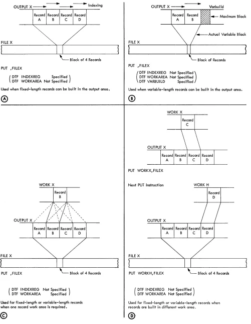
Blocked Fixed-Length Reco.·ds
BUILDING IN THE OUTPUT AREA
Whenever records are built directly in the output area, the first form of the PUT macro (PUT ,FILEX) is used. Blocked fixed-length records can be built in the out-put area, only if indexing is specified in'the DTF entries (INDEXREG). In this operation (Figure 12A), each PUT instruction increments the index register so that the next record can be built in the next record-area within the output block. Also, each PUT tests the
out-put area to see if it is filled. When it is, the block of rec ..
§
~~'I:I~~I=r~~lpe~~~tl~~21~~2-=&~--L-,-30~~~35~~4,--,0,--,,-,~~--L~--LRA--LN--LD~q_O
. P,U,T F 11.E,)( .P,U,T W.ORK)! ,J:,l LE)( . • .
[image:15.612.84.325.245.286.2]:
Figure 11. PUT Macro Instruction
ords is automatically written on tape, and the index register is initialized so that the following record will be built at the beginning of a new block.
When records are processed in the non-overlap mode,
the particular index register specified in the DTF entry must be included in the output area DA statement, and the individual fields should be labelled in the DA state-ment for reference throughout the program. This is
similar to the indexed input area DA statement (see
Figure 6). However, when records are processed in the
overlap mode, the index register and field labelling
must be omitted from the DA statement. The DA state-ment and fields must be set up in the same manner as described for the input area when blocked fixed-length records are processed with indexing and overlap (see Figure 7). To initialize the index register and provide
the address for the first record in a run, with overlap, a
PUT ,FILEX instruction must be issued before the first record is built in the output area.
BUILDING IN WORK AREAS
The first form of the PUT macro (PUT ,FILEX) is used whenever all records in an output file are to be built in the same work area. For this, the label of the work area must be included in the DTF entries and indexing must be omitted.
The second form of the PUT macro (PUT WORKX, FILEX) is used whenever records are to be built in
different work areas. It specifies the work area required
for each separate record. Both indexing and a work area specification must be omitted from the DTF en-tries, with this type of PUT instruction.
When work areas are used (Figure 12C, D), each PUT instruction moves an individual record from the specified work area to the proper location in the output area. Also, each PUT tests the output area to determine
if it is filled. If it is, the completed block of records is
automatically transferred to the output tape.
Work areas specified for output files may be the same work areas as specified for corresponding input files.
The principle of specifying the work area in the PUT
instruction is also used when an input area is to be
treated as'a work area. That is, each record is processed
(built for output) in the input area and then moved to the output area to be written on the output tape. When the input records are blocked in this operation, index-ing must be specified in the DTF entry for the input
area. If records are processed in the non-overlap mode,
the index register must be included in the DA state-ment for the input area. Also, the PUT macro is written with the label of the input area in the operand field
(Figure 13). If records are processed in the overlap
[image:15.612.84.323.663.703.2]- - - + ---....Id·
OUTPUT X ---. ____ n exmg
Record Record Record Record
A B C D
FILE X
PUT ,FILEX
( DTF I NDEXREG DTF WORKAREA Not Specified Specified )
Used when fixed-length records can be bui It in the output area.
OUTPUT X /
FILE X
PUT ,FILEX
WORK X
/ /
Record
B
( DTF I NDEXREG Not Specified ) DTF WORKAREA Specified Record
D
Used for fixed-length or variable-length records when one record work area is required.
[image:16.612.43.544.54.699.2]©
Figure 12. Writing Blocked Records
14
OUTPUT X ---... Varbuild
FILE X
B lock of Records PUT ,FILEX
(
DTF I NDEXREG DTF WORKAREA DTF VARBUILD
Not specified) Not Specified
Specified
Used when variable-length records can be built in the output area.
WORK X
Record C
OUTPUT X
Record Record Record Record
A B C D
PUT WORKX,FILEX
Next PUT Instruction WORK H
FILE X
OUTPUT X
Record Record Record A B C
Record D
PUT WORKH,FILEX ' - - B lock of 4 Records
( DTF I NDEXREG Not Specified) DTF WORKAREA Not Specified
Used for fixed-length or variable-length records when records are bu iI tin different work area.
t;.
L~~_~~~~~r~at~19~~~
• 5 I. Z!!__
~
50__
~~
:to__
~
40___
O~P~E~_N_D~
45 00 PUTJ
NPU:r A ,F.l LEXFigure 1a. Input Area Used as Work Area, Non-Overlap Mode
label of the input area in the operand field, the input
area is indicated by "0
+
Xn" (zero+
the number ofthe index register; Figure 14). This is necessary be-cause, with overlap, the index register always contains the address of the high-order position of the record to be processed. The DA statement and fields for this input area must be set up in the same manner as de-scribed for processing records in the input area with indexing and overlap (see Figure 7).
Figure 14:. Input Area Used as Work Area, Overlap Mode
Blocked Variable .. Length Records
One or more work areas may be used to build these records. The PUT instructions used to transfer
variable-length records from a work area to tape ar~ the same
as those described for bloeked fixed-length records,
under Building in Werk Areas. In addition, the length
of each record must be determined by the user's pro-gram and included in the record-length field. This length is then used by lacs in a test to see if the rec-ord fits in the allotted output-block area.
Blocked variable-length records can be built in the output area if the DTF entry labelled V ARBUILD is specified. Indexing cannot be specified for variable-length records. V ARB UILD performs functions for variable-.Iength blocked records that are similar to those performed by INDEXREG for fixed-length blocked records. In this operation (see Figure 12B), each PUT
instruction tests to see if the next record to be built will
fit in the allotted output-area block. If it will, the record
is built in the current block. If it will not, the block is
written on tape and the next: record is built at the be-ginning of a new block. For this operation and because the records are variable-length, the programmer must
determine the length of the next record before a PUT
instruction is issued at the end of building the present output record. That is, before he writes the PUT in-struction for output record A, he must read the input data for output reeord B and determine its length. Var-iable-length output records are generally developed from variable-length input records, perhaps modified by current-period card or tape records. The variable-length input must contain a record-variable-length field and this, with any current modification, will give the length of
the output record to be built. The programmer enters this length in the V ARBUILD field .
The DTF V ARBUILD entry must contain the label of a three-position field, which may be index register 2, index register 3, or any other 3-character area defined by the programmer. The V ARBUILD field performs two functions:
l. It makes the length of the next record to be built
(entered by the programmer) available to the laCS
routines. laCS can then determine if the present
block of records should be written, or if the next
record will fit in the block.
2. It makes available the address of the high-order position of the next record to be built. Thus, after the PUT instruction for record A, the address for record B is available for the programmer's use in
building record B in the output area. If an index
reg-ister is used for the V ARBUILD field, the individual fields can be built readily by indexing each
instruc-tion. If a three-position field other than index
regis-ter 2 or 3 is specified, it is used to modify each address as the fields are built.
A simplified program and three sample records (Fig-ure 15) illustrate the use of V ARBUILD. The illustra-tion assumes this setup:
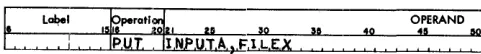
• DTF VARBUILD entry specifies X2 (index register 2) as the VARBUILD field.
• FILE A-Variable-length input file, with DTF-specified work area.
• FILE X-Variable-length output file.
• OUTPTX-100-Position output block (assembled address 50l).
• LENGTH-Work area to accumulate length of next record.
Several factors should be especially noted in this ill ustra tion:
1. The next record is read and its length determined before the PUT instruction for a record is issued.
2. The length of the next record is moved into the VARBUILD field (X2) before the PUT instruction is issued for the com-pleted record.
a. The PUT instruction tests to determine that the next record will fit in the current block.
4. After the PUT instruction, the address of the high-order position of the next record is available in the VARBUILD field (X2).
5. Comparable to factors 1-4 above, the first input record must be read and its length determined, and a PUT instruction must be given before the first output record is built. This makes the address for the first record available in the V AR-BUILD field. Similarly, if an output file is released (see RELSE Macro), a PUT instruction must be issued before the first record of the new block is built.
6. When the next record will not fit in the current block, the block is written and the address for the next record is pro-vided.
7. A record-length field is built in each output record by the programmer for later use when this record becomes input. This must always be located i.n the same positions within each record.
[image:17.613.78.319.64.91.2]PROGRAM
Line Label OPERAND
10 a. 40 45 ""
01 5,T,A,R, T, ; G:ET F,l L,E,A,
U I I
,...'-i-'-'---'--'-'--!--'--'-'-!-"",='lC, ... )(,'-I ... ll",)1.,..,'"' ... ' It ... ,. 1( .... [,' It,,--,-'...,L-J'~ /Steps to' Determ I no Length "'--'-'--'-' -'--'--'-'I...!'
1(.)1.1(.)(. l(,l(.l(, •• lt'lC,'J(. J of Next Output Record
03
04 I IMew. .,EN,G,T.IoI. 'J(,L, 05 I
0 ' I 07 I 08 I
O. i
Ip,U,T. F 1 LEX L L . L L . . ' - 0 . 3 . ' - , .'-L.~L.' - ' - - ' - ' - ' - ' - ' M,C.W, l),AT.E .•• S.+,X,2, 1 Build Output Record: ~
M,CW. '.U,S,T.N.O .11I .... ·U ~:;o:e~":i~~':r"~ ~OSition. 7 - 11"'--'-'-'
M.CW. ' v ~"'N 1..4 .'!l2 Record Length In Positions 13 -15 ~'-'
et., etc J Etc '
10 I I... S,T.A,R,T.
I I ,
SAMPLE RECOR,D--.;S'---_ _ _ _ _ --.--_ _ _ _ _ _ _ _ - - r _ _ _ --,
OUTPUT X
I
Record A - 30 Characters +I
Record a - so Characrers +I
I
*
5 6
o 0
1 0
OPERATION OPERAND FUNCTIONS
t
GET FILEA Move Input Record A to Work Area XXX XXX,XXX
}
Determine length of Output Record A - 30 characters XXXX XXX,XXXMCW LENGTH,X2 Move 30 to Index Register 2
PUT ,FILEX Output A (30 characters) will fit In hln .. k; X2 contaIns SOl MCW D'ff.~X2
}
MCW CUSTNO,IO+X2
0 MCW RECLEN,14+X2 Build Output Record A etc. etc.
f
GET FILEA Move Input Record B to Work Area XXX XXX,XXX}
Determine length of Output Record B - SO characters XXXX XXX,XXX® MCW LENGTH,X2 Move SO to Index Regiller 2
~
PUT ,FILEX Output A completed; Output B (SO characters) will fit In block; X2 contains 531MCW DA~.~X2
}
MCW CUSTNO,IO+X2
0 MCW RECLEN,14+X2 Build Output Record B etc. etc.
i
GET FILEA Move Input Record C to Work Area XXX XXX,XXX}
Determine length of Output Record C - 40 characters XXXX XXX,XXX® MCW LENGTH,X2 Move 40 to Index Register 2
[image:18.612.45.289.60.496.2]~
PUT ,FILEX Output B completed; Output C (40 characters) will nat fit In block; Block Is written on tape; X2 contains 501 Note: Circled numbers refer to notes in text.Figure 15. Variable-Length Records Built with VARBUILD
Unblocked Records
When unblocked records (card, tape, or printer) are handled, each PUT instruction transfers a single record
from the output area to the output file. If a work area
is specified in either the DTF entry or the PUT
instruc-tion (see Building in Work Areas), each PUT first moves
the record from that work area to the output area, and then transfers it to the output file. A work area is re-quired for card output records. They cannot be built directly in the output area because of the laCS rou-tines for card punch checking.
If unblocked tape records are to be built in two
out-put areas (overlap mode), indexing is required. The
16
programming for this operation is the same as that de-scribed for blocked fixed-length records processed with indexing and overlap:
STACKER SELECTION
Card output files may be selected to stack in pocket 4 or 8. This selection may be specified in the DTF entries (CARDPOC) when all cards are to be stacked in the same pocket, or it may be specified in the PUT macro, but not in both. It is specified in PUT by modifying the basic form of the macro and writing the pocket number as the third operand (Figure 16).
Label ., ~peratl:; leI OPERAND
I, 2& liD lIli 40 411 110
:
PU.T. Fl LE)(. .•. 4, ,I.
I I II PUT Iwolt Ie.
)C, .. 1'1'.1 L,E.-.c.. •• 8,
[image:18.612.305.544.224.265.2]I
Figure 16. PUT Instruction with Punch Stacker Selection
Unlike card input files, this selection applies to card output records processed in either the non-overlap or overlap mode.
PRINTER FORMS CONTROL
Spacing and skipping of forms can be controlled by the laCS routines. The operation may be specified in the DTF entries or in the PUT instruction, but not in both.
In either case, the standard IBM 1401 d-character for
forms control is used to indicate the desired operation
(see System Operation Reference Manual for IBM
1401 and 1460, Form A24-3067). The d-character is
specified in the DTF entry (FORMCNTL) if the same operation is to be performed for each printed line,
such as double-spacing. It is specified in the PUT
in-struction (Figure 17) whenever different spacing or skipping is to occur for different printed lines.
Label OPERAND
40 411 110
1
Figure 17. PUT Instruction with Forms Control
The layout of a form may require certain spacing (or
skipping) either before or after a particular line of
printing, or both before and after printing. When one
control (before or after) is required, the d-character is
entered as the third operand in the PUT instruction.
For control both before and after, the d-charact:er for
immediate spacing or skipping (before printing) must
be entered as the third operand, and the d-character for
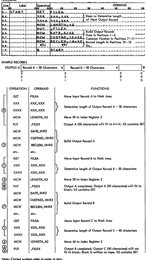
[image:18.612.305.544.530.572.2]RELSE
(IRe/ease)Macro
The release macro instruction is used in conjunction with blocked tape records. It allows the programmer to skip the remaining records in a block and continue processing with the first record of the next block. This function applies to a job in which records on tape are categorized and each category (perhaps a major group-ing) is planned to start as the first record in a block. For example, sales data may be recorded and analyzed by division (major), district (intermediate), and branch
office (minor). Then, if management frequently requires
special analyses of sales for certain specified divisions,
these analy~es can be obtained quickly and efficiently
with a system planned so that the records for each divi-sion start at the beginning of a new block of records. The specified division can be located readily by
check-ing only the first record in each block. If that record is
not in the specified division, the other records in the block can be ignored and the first record of the next block can be checked.
The symbolic name of the file, specified in the DTF entry, is entered in the operand field of the re-lease instruction. In the overlap mode, the word OVER-LAP must also be entered in the operand field (Figure 18). When this is an input file, the next GET instruction reads in a new block of records and makes the first
rec-ord available for processing. If indexing is used, the
index register is initialized. Because input records are skipped in this operation, record counts and hash totals cannot be taken.
§
Qbel 1~~perQti~121 25~ RELSEF~L£A
: R&:L.SItFlLEA.OVE,R,L,A,P"" ,
40
[image:19.613.75.316.473.514.2]OPERAND 45 50 lIO
Figure 18. RELSE Macro Instruction
When an output file is released, the next PUT in-struction causes the existing block of records to be writ-ten on tape. The new record becomes the first record of a new block. With blocked fixed-length records, any unfilled portion of the block is padded with the charac-ter specified in the DTF entry (PADDING), or with blanks. The padded records are included in any record counts or hash totals. With variable-length records and an unfilled portion, a short block is written.
When output records are built in work areas, the control number in each record can be examined (by the user's program) as the record is being built, to deter-mine whether or not the record is the first one of a new
major group. If it is, RELSE is issued and the PUT
in-struction for that record causes the existing block to be
written before the record is moved from the work area
to the output area. If records are built directly in the
output area, however, examining the control number of a record as it is built would cause the first record of a new group to be erroneously included in the previous block when RELSE and PUT for that record are is-sued. Therefore, programming must be provided to
make sure that the first record of a new group is in a
new block. One method is to determine the control
number of the next output record after the PUT
in-struction is issued at the end of building each record. If the next record belongs in a new group, RELSE is issued after the PUT instruction for the last record of the present group.
SPACE/SKIP Macro
Tape Labels
Data processing installations using magnetic tape stor-age have many reels of tape to be stored and handled. To ensure that the correct tape reel of data is used in
each job, it is common practice to identify the tape
it-self with header and trailer labels, in addition to a
printed label on the outside of the reel. A header label is the first record on tape and contains such factors as identification numbers, identification name, and effec-tive dates. A trailer label is at the end of data on tape and provides control totals and an indication that the reel is, or is not, the last reel for the job.
The format of both header and trailer labels may be
the IBM standard form, or it may be a different
arrange-ment (nonstandard) planned by the user. The IOCS routines can process tapes with either standard or non-standard labels, or without labels. However, only stand-ard labels are automatically written on output tapes and automatically checked on input (or output) tapes. Non-standard labels are written or checked by the user's pro-gram, outside the IOCS routines. In each job the user must specify in the DIOCS entries (LABELDEF) and in the DTF entries (TYPELABEL) the type of labels to be processed.
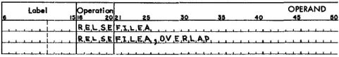
Standard Header
Label
A standard header label is 80 characters in length (Fig-ure 19). The first 40 positions are used for seven fields that contain standard identifying information, and the remaining 40 positions are blank. The first two fields (Header and Tape Serial Number) permanently iden-tify the reel itself. The other five fields ideniden-tify the job and are automatically written (or checked) with
infor-mation specified in the DTF entries. If a job requires
more than one tape reel of data, the same header infor-mation (with the exception of tape and reel numbers) is repeated on all reels. Information may be written or checked in the last 40 positions, if desired, by the user's
program (see Label Operation).
CD
@
®
8)
®
Header Tape File Reel
lead-In
Portion Serial Serial Sequence
Number Number Number
,
,
,
,
I'H 0 R'b x x x x x x x x x x -lx x x:b x x
When an input tape with a standard header label is to be processed, the user must specify (in DTF CHECK-LABEL) the checking he wants performed by the IOCS routines: complete (the standard identifying
in-formation), partial (name only), or none at all. If an
error is detected in this check, a programmed halt oc-curs. After the halt, operation can be started using the same tape, if desired, or the tape can be replaced. In this case, the header of the new tape is checked before data is processed.
When an output tape is to be written, the effective
dates in the old header should be checked to ensure
that the data on the tape is no longer active and may be destroyed. Therefore, IOCS automatically checks the retention cycle in the old header against the time elapsed between the creation date and today's date. If an error is detected, a programmed halt occurs. Then, the tape may be changed, or operation may be started using the same tape.
The seven identifying fields in the standard header label are:
l. Header-consists of the digit 1, the letters HDR,
and a blank position.
When a new reel of tape is received in an installa-tion and before it is used in an IOCS job, the char-acters 1BLNK should be written in this field as a temporary header identification. The first time rec-ords are written by IOCS, 1BLNK is automatically replaced with the standard header identification (lHDRb).
Input Tape: This field identifies the first record as the header label.
Output Tape: This field is written automatically by the IOCS routines.
2. Tape Serial Number-5 digits
This is the sequential number of the tape reel within the whole installation. As soon as a new reel of tape is received in the installation, it should be identified in this field with the next available num-ber. The IOCS routines do not affect this numnum-ber.
@
CD
~,
,
File Creation Retention Blank or\ Identification Date Cycle User's I Data
Name Information
Year
,
Day II
.\
x x x x x x x x x x:x x x -:x x x:b
,
I [image:20.612.48.545.631.706.2]I I I
15
I I I
110
I I I
115 1 1 1 120 1 1 1 1251 1 1 [ [30
I I I
pS
I I I
140
I I I
7
180Figure 19. Schematic of Standard Header Label
3. File Serial Number-5 digits
This generally represents a job number in an in-stallation.
Input Tape: When the header is to be completely checked, this number must be specified in the DTF entry SERIALNUM.
Output Tape: The number to be recorded must be specified in the DTF entry SERIALNUM, unless the user plans to make this number the same as thc tape serial number. If the tape serial number is used and the job requires two or more reels, the
tape number of the first reel becomes the file serial
nnmber on all reels.
4. Reel Sequence Number-consists of a minus sign, 3 digits, and a blank posiltion.
This field is used to number the reels in a multi-reel job. The number oJE the first multi-reel is 001 unless the lUser specifies some other number (3 digits) in the DTF entry REELSEQ.
Input Tape: When the header is to be completely checked, reel sequence is checked automatically. Output Tape: Reels, after the first, are serially
num-bered automatically.
5. File Identification Name-10 characters
This may be a job name in an installation. This
identification must be ten positions long with a
sig-nificant character, not a blank, in the tenth position. Also, no more than one blank may separate two sig-nificant characters within the field.
Input Tape: When the header is to be checked (either completely or partially) this name must be specified in the DTF entry HEADER.
Output Tape: The name to be recorded must be specified in the DTF entry HEADER.
6. Creation Date-5 digits
The dating system consists of 2 digits for the year, followed by 3 digits for the day of the year.
Input Tape: When the header is to be completely checked, this date mlllst be specified in the DTF entry HEADER.
[image:21.620.80.580.624.700.2]Output Tape: The date is taken from today's date in storage. The user must load the date in storage positions 195-199. To do this, he punches a card
Figure 20. Schematic of Standard Trailer Label
with today's date and loading instructions, and inserts it in the object-program condensed deck following the IOCS portion:
COLUMNS
1-5 40-46 47-53 54-60 61-67 68-71
PUNCH
(Today's datc) L005199 NOOOOOO NOOOOOO NOOOOOO 1040
7. Retention Cycle-consists of a minus sign, 3 digits, and a blank position.
This specifies the number of days after the crea-tion date that the tape is to be kept active.
Input Tape: When the header is to be completely checked, the number of days (3 digits) must be specified in the DTF entry HEADER.
Output Tape: The number of days (3 digits) to be recorded must be specified in DTF HEADER.
The information for header fields 3-7 is specified in a RDLlN information card, whenever a RDLlN macro
instruction is used in a program (see RDLIN Macro).
Standard
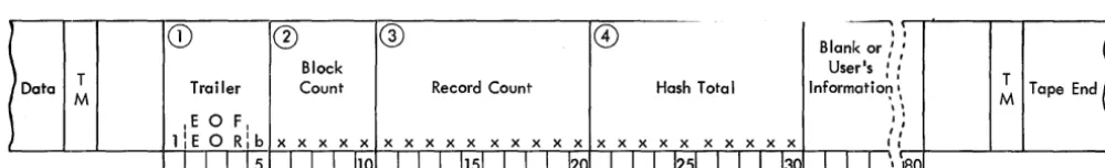
Trailer Label
A standard trailer label is 80 characters in length (Fig-ure 20). The first 30 positions are used for four fields that contain standard control checks, and the remaining 50 positions are blank. The first field indicates whether or not this is the last reel of data for a job. The other three fields provide control totals and are written (or
checked) with totals accumulated during the run, if
specified in the DTF entries. Information may be
writ-ten or checked in the last 50 positions, if desired, by the
user's program (see Label Operation).
As he does with header labels, the user must specify checking in the DTF entries (CHECKLABEL) when-ever he wants the IOCS routines to check the standard trailer label of an input tape. The three control totals are checked, and if an error is detected a programmed
halt occurs. Operation can be resumed, if desired, or
the error can be displayed for the operator to investi-gate.
The four fields in the standard trailer label are:
The letters EOF (end of file) indicate that this is all the data for the job. EaR (end of reel) indicates that this is the end of a reel of tape but one or more reels follow for the same job.
Input Tape: The field identifies the record as a trailer label and indicates if another reel follows. Output Tape: The letters EOF are written
automati-cally when a CLOSE macro instruction is given. The letters EaR are written automatically when the tape reflective spot is sensed or when a FEORL macro instruction is given.
2. Block C ount-5 digits
A count of the number of blocks processed is al-ways accumulated automatically by the lacs rou-tines. In the case of unblocked records, this count is the same as a record count.
Input Tape: When the trailer label is to be checked, the count accumulated is compared to the count recorded on the tape when it was written.
Output Tape: The accumulated count is written au-tomatically.
3. Record Count-l0 digits
This is a count of the number of records processed. With unblocked records, this is the same as the block count.
Input Tape: When a trailer that contains a record count is to be checked, this must be specified in the DTF entry TOTALS.
Output Tape: This count