Reference Manual
MAJOR REVISION (April, 1962)
This edition, A24-1403-5, obsoletes A24-1403-4 and all earlier editions. Significant changes have been made throughout the manual, and this new edition should be reviewed in its entirety. This edition also obsoletes these publications:
G24-1438 IBM 1401 Data Processing System Bulletin Early Card Read Special Feature for IBM 1402 Card Read-Punch
G24-1458 IBM 1401 Data Processing System Bulletin Processing Overlap
G24-1461 IBM 1401 Data Processing System Bulletin
Processing Overlap: Processing Time During Magnetic Tape Operations
N24-0001 No.1 Oct. 23, 1961 N24-0004 No.2 Oct. 30, 1961 N24-0005 No.3 Oct. 31, 1961 N24-0009 No.4 Dec. 18, 1961 N24-0010 No.5 Dec. 18, 1961 N24-0018 No.6 Feb. 28, 1962
© 1960, 1961, 1962 by International Business Machines Corporation
Preface
This manual is a reference text for the IBM 1401 Data Processing System. It provides a detailed explanation of operation codes and the function of the system's components. The reader should have a knowledge of the 1401 system and programming techniques. The reader should be familiar with the General Informa-tion Manual, IBM 1401 Data Processing System, form D24-1401, and the various publications on applied pro-gramming material, such as Symbolic Propro-gramming System (SPS) and Autocoder.
The manual is divided into these sections:
• operation codes • operating features • systems timing • appendix
The sections are independent and· need not be used in the order in which they appear.
This manual is intended for the use of programmers and systems personnel who have a general knowledge
of the IBM 1401 Data Processing System and who
require a reference text for detailed information. The manual can also be used as a training aid in the in-struction of programmers and operators.
Contents
Introduction ... 7
The Stored Program ... ... 7
Other Input-Output Units for the IBM 1401 System ... 7
The IBM 1401 Used with Other IBM Systems ... 8
Physical Features ... 9
Solid-State Circuitry .... ... 9
Advanced Systems Design ... 9
IBM 1401 Processing Unit ... 9
IB}'! '1402 Card Read-Punch ... 10
IBM 1403 Printer ... 11
~1agnetic-Core Storage ... ... ... ... ... 11
Magnetic-Tape Storage ... 12
Magnetic-Disk Storage ... 12
Language ... 13
Processing ... 14
Stored Program Instructions ... 15
Addressing ... 18
Operation of IBM 1401 Registers ... 19
IBM 1401 Programming Systems ... 23
Symbolic Languages ... ... 23
IBM 1401 Symbolic Programming System (SPS) ... 23
IBM 1401 Autocoder ... 23
Input-Output Control System (IOCS) ... 27
IBM 1401 Report Program Generator (RPG) ... 27
Operation Codes ... ... 28
Arithmetic Operations ... ... ... ... ... ... 28
Logic Operations ... 32
Clear, Move, Load, and Word Mark Operations ... 35
Editing ... 41
Input-Output Operations ... 44
Card Read Instructions .... ... ... ... 44
Punch Instructions ... ... ... ... ... ... 45
Print Instructions ... ... ... ... 46
Combination Instructions ... 48
Document Control Instructions ... 51
Magnetic Tape ... 53
Data Flow... ... 53
Magnetic Tape Characteristics ... 53
Tape Units ... 55
IBM 729 ~1agnetic Tape Unit ... 55
IBM 7330 Magnetic Tape Unit ... 55
Tape Intermix ... ... 55
Tape Checking ... 56
Magnetic-Tape Operations ... 57
Tape Instructions ... 57
IBM RAMAC® 1401 System ... 63
IBM 1405 Disk Storage Instructions ... 65
IBM 1407 Console Inquiry Station ... 70
IBM 1407 Console Inquiry Station Instructions ... 71
Special Features ... 74
Multiply-Divide Feature ... 74
Increased Core Storage ... 76
Read Release and Punch Release Feature ... 78
Punch Feed Read Feature ... 80
Print Storage Feature ... 82
Additional Print Control Feature ... 82
Expanded Print Edit Feature ... 82
Indexing .Feature ... 84
Store Address Register Feature ... 85,
Move Record Feature ... 86,
High-Low-Equal Compare Feature ... 86
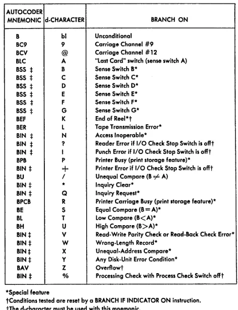
Sense Switches Feature ... ... 87
Compressed Tape Operations Feature ... 87
Column Binary Feature ... 89
Numerical Print Feature ... 94
Interchangeable Chain Cartridge Adapter ... 94
Interchangeable 51-Column Read Feed ... 95
Early Card Read Feature .... ... 97
Processing Overlap Feature ... 97
Address Modification ... 106
Address Modification vVithout Indexing Feature 106 Address Modification with Indexing Feature ... 108
Operating Features ... 109
IBM 1401 Console Keys, Lights, and Switches .. 109
Auxiliary Console ... 116
Auxiliary Console Switches ... 116
IBM 1402 Card Read-Punch Operating Keys, Lights, and Switches ... 118
IBM 1403 Printer Operating Keys, Lights, and Switches ... 119
Printer Controls ... 119
Carriage Controls .... ... ... ... 120
Tape-Controlled Carriage ... 123
IBM 1405 Disk Storage Unit Indicator Lights ... 128
IBM 1407 Console Inquiry Station Keys and Lights ... 129
Operating Pointers ... ... ... ... ... ... 130
IBM 729 and 7330 Magnetic Tape Units Operating Keys and Lights ... 134
Operating Pointers ... 135
Console Operation . ... 136
Console Inquiry Station Operation ... ~... 136
Timing ... 140 Appendix ... 160
Timing Input and Output Operations ... 140
Simultaneous Input-Output Operations ... 144
Processing Time ... 149
Tape Processing Time ... 152
Processing Overlap Timing ... 156
Disk Storage,Access Time ... 158
Fonn Design .... ... ... ... 160
Program Loading Routine ... 164
Clear Storage Routine ... 165
Multiplication and Division Subroutines .... ... 166
IBM 1401 Operation Codes ... 169
mM 1401 Character Code Chart in Collating Sequence .. 170
As the recordkeeping requirements of business and in-dustry continue to mount, the need for a data processing system that can be expanded to meet these requirements becomes apparent. A system is desired that can fill present needs, and that can expand as the burden of recordkeeping increases. Large-scale systems and small-scale systems are available, but a gap existed where no . system seemed to do processing on an economical
job-cost basis.
To fill this gap, IBM developed the IBM 1401 Data Processing System (Figure 1). The IBM 1401 is a solid-state, high-speed processing system with the program flexibility of larger systems.
The 1401 provides system configurations to meet the requirements for processing unit records, magnetic tape and magnetic disk records, and character-sensed docu-ments.
The 1401 system provides high-speed input-output and arithmetic and logical ability, with the advantages of stored-program techniques. Various methods of pro-gramming are available. Some of the methods are: the easy-to-use actual language, the symbolic program-ming system (SPS) of mnemonic instructions, and IBM 1401 Autocoder.
The IBM 1401 Processing Unit handles
variable-length alphamerical data and instructions. This means no space is wasted by filling in fixed-length words.
Variable word length, high internal processing speed, fast input and output, powerful editing ability, and di-rect accumulation in storage make the IBM 1401 Data Processing System an efficient and valuable tool to meet today's data processing requirements.
IBM 1401 Data Processing Systems can be considered
in three basic concepts: card systems, tape systems, and RAMAC® systems.
IBM 1401 card systems are planned for procedures involving large volumes of card documents as source data and output, with particular advantage to applica-,tions requiring re-entry data.
IBM 1401 tape systems are for handling magnetic tape, with all the advantages of compact record han-dling and storage for high-speed data processing.
IBM RAMAC 1401 systems permit rapid access to large volumes of repetitive data without the necessity of processing large card volumes or sorting tape records.
IBM 1401 Data Processing System
The Stored Program
The IBM 1401 performs its functions by executing a series of instructions at high speed. A particular set of instructions, designed to solve a specific problem, is known as a program. Because the 1401 stores its instruc-tions internally, it is called a stored program system.
The 1401 normally executes instructions sequentially . But sometimes it is necessary to skip over a particular group of instructions, or otherwise change the sequence of the program. Branch instructions are provided in the system to make it possible to alter the program and take the next instruction from another area of the stored program. This feature also makes it possible to repeat an instruction, or group of instructions, as often as desired.
A series of programmed tests determines the logical path of the program. These tests are made at various points in the program to control the course of program step execution for specific conditions that can arise during processing.
Other Input-Output Units for the IBM 1401 System
To meet the ever increasing needs of business for fast, economical processing of data, the IBM 1401 Data Proc-essing System can accept data made available to it in a variety of forms. Besides the normal input in the form of punched cards and magnetic tape, other devices that greatly increase the efficiency and flexibility of the 1401 have been provided. These units make it possible to read punched paper tape, magnetic ink characters, and printed characters, and to transmit data between 1401's or a 1401 and a tape transmission terminal.
The IBM 1011 Paper Tape Reader enables the direct input of data punched in paper tape into the 1401 system. Present day accounting and data processing practices are such that in many cases the source data for a central data processing system originates at loca-tions remote from the central system. The ease and economy in transmitting punched paper tape make it an ideal medium for this type of reporting. A concise description of the 1011 including operating features, control panel summary, and IBM 1401 operation codes is found in the General Information Manual, IBM 1011
Paper Tape Reader, form D24-1044.
The IBM 1419 Magnetic Character Reader serves as a means of input to the 1401 system. This merging of machines increases Hexibility and control in banking operations. Thus, magnetically-inscribed characters are read by the magnetic character reader and sent to 1401 core storage for processing. A full description of the 1419, including operating features and IBM 1401 oper-ation codes, is included in the General Informoper-ation Manual, IBM 1219 Reader Sorter and IBM 1419
Mag-netic Character Reader, form D24-9000.
Re-entry documents can be read directly into the core storage unit of the 1401 by using the IBM 1418 Optical Character Reader as an input device. This means the elimination, in many cases, of preparing data for systems use when it is returned with a re-mittance. In many applications, this allows all functions necessary for processing data, from source document through the final report, to be accomplished in one operation. The use and functions of the 1418 are described in the Reference Manual, IBM 1418 Optical
Character Reader, form A24-1418.
Many businesses with decentralized accounting op-erations have data processing installations at branch offices as well as at the headquarters location. The source data received from the branch offices enables the central office to prepare consolidated reports to
meet their accounting needs. The IBM 1009 Data
Transmission Unit allows high-speed, two-way
com-munication between two IBM 1401 Data Processing
Systems or between a 1401 and an IBM 7701 Magnetic Tape Transmission Terminal. The operation and func-tioning of the 1009 is described in the Reference
Manual, IBM 1009 Data Transmission Unit, form
A24-1039.
The IBM 7701 Magnetic Tape Transmission
Termi-nal prOVides communication between outlying tape installations and a central data processing system, without intermediate conversion steps. Straight-line data How from a 1401 tape system to a large-scale system such as an IBM 700 or 7000 series data process-ing system is now a fact. This development results in a fast, economical collection, processing, and return of data not previously possible. The functions and oper-ating features of the 7701 are described in the
Refer-ence Manual, IBM 7701 Magnetic Tape Transmission
Terminal, form A22-6527.
The IBM 1404 Printer is another output medium for the 1401 system. It is a combination printer capable of processing either separate card documents or con-tinuous forms. Under control of the 1401 stored pro-gram, and the tape-controlled carriage, this unique
printer can process continuous forms at a rated speed of 600 lines per minute; or it can print on card docu-ments at a maximum rate of 800 cards per minute. The 1404 can process cards ranging in size from 51 columns to 160 columns. It can also process two cards (either 51- or 80-columns) at a time. As many as 25 lines of data, either from 1401 core storage or from the card itself, can be printed on each card. Instructions, as well as the functional and operational character-istics, are covered in the 1401 Data Processing System bulletin, IBM 1404 Printer, form G24-1446.
Today's modern busines~ requires fast, efficient and inexpensive intercommunication of data between branch, or field, locations and the central, or home, office. The IBM 1012 Tape Punch provides this means of communication and meets all these requirements. The IBM 1012 Tape Punch, connected to an IBM 1401 Data Processing System, is an ideal medium for re-cording data processed at remote locations. Data punched in paper or Mylar* tape can be transmitted quickly and inexpensively to a central location by common carrier lines.
At the central location, the data recorded in the tape can be converted to punched cards or used as di-rect input to a central data processing ·system. A de-tailed description of the IBM 1012, including operating features and IBM 1401 operation codes, are found in
the General Information Manual, IBM 1012 Tape
Punch, form D24-1077.
The.I8M 7407 Used with Other IBM Systems
IBM 7070 Data Processing System
The IBM 1401 Data Processing System has additional Hexibility when it is used with the tape-oriented con-figuration of the IBM 7070 Data Processing System. The 1401 can produce, edit, sort, print, punch, and further manipulate tape data used by the 7070, thus providing more time for the operations that are more efficient and practical for each system.
IBM Scientific Data Processing Systems
The column binary feature enables the 1401 to process card and tape data recorded in binary form. This abil-ity makes the 1401 especially useful as an auxiliary system for the IBM 704, IBM 709, and IBM 7090 Data Processing Systems.
Solid-State Circuitry
Transistorization of mM 1401 components is a sig-nificant design characteristic. Transistors are relatively
inexpensive, are easy to maintain, and increase
reli-ability in the system (Figure 2). Space requirements,
heat dissipation, and power requirements are carefully controlled.
The components that require operator attention are
conveniently located.
-1- ---
f •,
..
-,
•
.
~.
•
• to '•
,~•
O·
•
• - II.
•
•
'I!
•
•
-()
,
•
...
•
..
..
•
• •
(
•
•
I I•
•
-
..
•
•
•
•
-•
•
•
•
•
'"
•
tIFigure 2. Transistor Cards
Physical Features
Advanced System Design
Advanced system design makes the mM 1401 a
com-plete, independent, accounting system. But it can also
perform low-cost direct input and output, and auxiliary
tape operations for large-scale data processing systems.
Th~ entire system is controlled by the stored
pro-gram. Timesaving features, such as the powerful edit-ing function, and the elimination of control panels, provide increased flexibility for application develop-ment. The ability to use magnetic tape means economy
in recording, transporting, and storing large volumes
of information in compact form.
IBM 1401 Processing Unit
The IBM 1401 Processing Unit (Figure 3) contains the
core storage and circuitry that perform the machine
logic.
Storage capacity is 1400, 2000, 4000, 8000, 12,000 or
16,000 alphamerical characters of 8-bit core storage. These eight bits consist of six bits for binary-coded decimals, a check bit, and an eighth bit for field defi-nition.
Figure 3. IBM 1401 Processing Unit
Figure 4. IBM 1402 Card Read-Punch
IBM J 402 Card Read-Punch
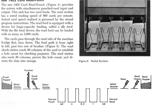
The IBM 1402 Card Read-Punch (Figure 4) provides the system with simultaneous punched-card input and output. This unit has two card feeds. The read section has a rated reading speed of 800 cards per minute. Actual card speed realized is governed by the stored program instructions. The read feed is equipped with a device for large-capacity loading, called a file feed.
With the file feed device, the read feed can be loaded with as many as 3,000 cards.
The cards pass through the read side of the machine 9-edge first, face down. The feed path is from right to left, past two sets of brushes (Figure 5). The read check station reads 80 columns of the card to establish
a hole count for checking purposes. The read station
also reads 80 columns, proves the hole count, and di-rects the data into storage.
Punches
The punch section has a rated speed of 250 cards per minute. The card hopper capacity is 1,200 cards.
Cards feed 12-edge first, face down. The feed path is left to right. Cards pass a blank station, a punch station, and a read station (Figure 5). The punch statio con-sists of 80 punch magnets for recording information. The punch read station has 80 brushes that read the data punched in the card for a hole-count check.
The IBM 1402 Card Read-Punch is equipped with
five radial type stackers (Figure 6), with a capacity of 1,000 cards each. Cards from each feed can be pro-gram-directed to three of the five pockets.
The cards from the read side go to the NR (normal
read) pocket unless program-directed to pockets 1 or 2. The cards from the punch side go to the NP (normal punch) pocket unless program-directed to pockets 4 or 8.
The center pocket (8/2) can receive cards from either feed. However, card merging can be accom
[image:11.611.39.559.364.726.2]-plished only under certain, very limited conditions.
Figure 6. Radial Stackers
Read
G~~~er
I~
Blank
Station
1
Punch
Check
~
;;!:k'.,
i:!:k'.,
21k_iil
NormaUUUUU=
Punch
Read
NP
8/2NR
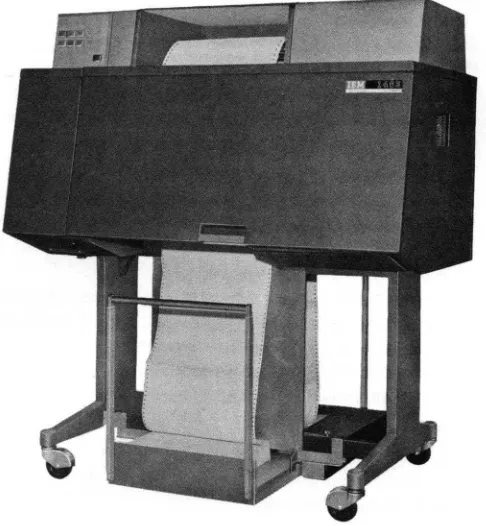
Figure 7. IBM 1403 Printer
IBM 1403 Printer
The IBM 1403 Printer (Figure 7) is another output
me-dium for the IBM 1401 Data Processing System. This
. unit has a rated printing speed of 600 lines per minute.
The standard printing capacity is 100 positions, with an additional 32 positions available as a special feature.
Each position can print 48 different characters: 26 a:Iphabetic; 10 numerical; and 12 special characters
(& , . D - $
* /
% # @=1=).
Vertical spacing and skipping are initiated by the
stored program. Horizontal spacing is 10 characters to
the inch. Vertical spacing of either six or eight lines to the inch can be manually selected by the operator. The
paper transport mechanism for line spacing is a single-speed, tape-controlled carriage in the IBM 1401 card
system, Model A. Other models (B, C, and D) use a
dual-speed, tape-controlled carriage that permits skip-ping at the rate of 75 inches per second for skips of more than 8 lines, as compared to the single-speed
car-riage that has a constant speed of 33 inches per second for all skips.
METHOD OF PRINTING
The alphabetic, numerical, and special characters are assembled in a chain (Figure 8). As the chain travels
in a horizontal plane, each character is printed as it is positioned opposite a magnet-driven hammer that
presses the form against the chain.
As each hammer magnet is energized, it is checked
against the corresponding position in the print area
[image:12.611.74.317.69.332.2]132 Printing Positions
Figure 8. Printing Mechanism Schematic
Complete Chain Composed of Five
48-Cha ra cter Sections
of core storage to insure that printed output is
accu-rate. Also the machine checks to insure that the char-acter is printed in the correct print position, that only valid characters are printed, and that over-printing does not occur .
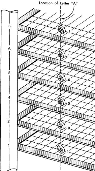
Magnetic-Core Storage
The IBM 1401 Data Processing System uses
magnetic-core storage for storing instructions and data (Figures
9 and 10). All data in core storage is instantly
avail-Figure 9. Magnetic Core Storage Unit
[image:12.611.330.575.500.729.2]Figure 10. The Letter A Represented in Magnetic Core Storage
able, and the special design of the core-storage unit - makes each position individually addressable. This means an instruction can designate the exact storage locations that contain the data needed for that step.
The physical make-up of each core-storage location makes it possible for the IBM 1401 to perform arithme-tic operations directly in the storage area. (This is called add to storage logic.)
Magnetic-Tape
Storage
Magnetic tape is made of plastic material, coated with a metallic oxide. It can be easily magnetized in tiny spots, so that patterns of these magnetized spots are codes for digits, alphabetic characters, and special characters.
Data can be read from a variety of sources, and written on the tape. Magnetic spots, representing in-formation written on the tape, remain until changed by positive action.
This means that besides being used as data storage, this data itself can be part of input and output.
This makes magnetic tape an ideal storage medium for a large volume of data, because there is no limit to the amount of information that can be kept perma-nently. The reels of tape can be removed from the system and filed. They can also be transported from place to place and used in other systems.
Data stored on magnetic tape is read sequentially. The data processing system can search the tape to find the data to be used. Program steps can be stored on magnetic tapes, which are commonly used to set up a library or file of procedures.
Another advantage of magnetic-tape storage is that a reel of tape, produced as an output of a procedure, can be removed from the data processing system. Re-ports can be written using an independent unit, while the data processing system proceeds with the next program to be pedormed.
Magnetic-Disk. Storage
Magnetic disks are thin metal disks, two feet in diam-eter, that are coated on both sides with a ferrous oxide recording material. These disks are mounted on a ver-tical shaft, and are separated from one another. As the shaft revolves, it spins the disks at 1200 rpm.
Information is recorded on disks in the form of mag-netized spots located in concentric tracks on each disk surface.
At the side of the stack of disks (Figure 11), one or more access arms can move to any desired track on any disk under stored-program control. Magnetic recording heads mounted on the access arms write or read infor-mation as directed by the program. Each access arm is forked so that when it enters the stack of spinning disks, a recording head is carried to both sides of a disk. Thus, it is possible to read or write on either surface of a disk.
The magnetic disk can be used repetitively. Each time new information·is stored in a track, it erases the data formerly stored there. Records can be read from disks as often as desired until they are written over or erased.
return the updated record to the storage unit. Also, the 1401 can process other data within core storage while the access mechanism searches for a record.
Language
In the punched-card area of data processing, the lan-guage of the machine consists of holes punched in a card. As data processing needs increase, the basic card language remains the same. But in the transition from unit-record systems to the mM 1401 Data Processing System, and from there to computer systems, another faster, more flexible machine language emerges.
Just as each digit, letter in the alphabet, or special character is coded into a card as a punched hole or a combination of punched holes, it is coded into mag-netic storage as a pattern of magnetized spots.
Many different code patterns can be set up. The internal code used in the mM 1401 Data Processing System is called binary-coded decimal. All data and
in-structions are translated into this code as they are stored. No matter how information is introduced into the system (most commonly by means of punched cards or magnetic tape), the binary-coded-decimal code is used in all data flow and processing from that point on, until it is translated into printed output as
reports and documents are written, or converted to punched-card code, for punched-card output. Convert-ing input data to the 1401 internal code, and
subse-quently reconverting, is completely automatic. Figure 11. Access Arm
Processing
The manipulation that data undergoes in order to achieve desired results is called processing, and the part of the 1401 system that houses these operations is called the processing unit.
Logic
The logic function of any kind of data processing sys-tem is the ability to execute program steps; but even more, the ability to evaluate conditions and select alternative program steps on the basis of those condi-tions.
In unit-record equipment, an example of this logic is selector-controlled operations based on an X-punch or No X-punch, or based on a positive or negative value, or perhaps based on a comparison of control numbers in a given card field.
Similarly, the logic functions of the 1401 system control comparisons, branching (alternative decisions similar in concept to selector-controlled procedures), move and load operations (transfer of data or instruc-tions ), and the general ability to perform a compli-cated set of program steps with necessary variations.
Arithmetic
The mM 1401 Processing Unit can add, subtract,
mul-tiply, and divide. Multiplication and division can be accomplished in any 1401 system, by programmed sub-routines. When the extent of the calculations might otherwise limit the operation, a special multiply-divide feature is available.
Editing
As the term implies, editing adds significance to output data by punctuating and inserting special characters
and symbols. The mM 1401 has a unique ability to
per-form this function, automatically, with simple program instructions.
Internal Checking
Advanced circuit design is built into the 1401 to assure accurate results. Self-checking within the machine consists of parity, validity, and hole count.
14
PARITY CHECKING
The mM 1401 checks characters at various locations in
the system for odd-bit configurations. The six-bit, binary-coded-decimal internal language used by the 1401 also has a check bit for odd-bit checking pur-poses, and a word mark. The check bit is added to all characters that would otherwise have an even num-ber of bits.
Example: A character P has a binary-coded decimal
equivalent of B 4 2 l. The check bit is added to give this character an odd number of bits (C B 4 2 1).
If the character has a word mark associated with it, the word mark is included in the test for odd-bit parity.
Example: If the character P has a word mark, the the check bit is not added because the bit configura-tion is odd (WM B 421).
Whenever a parity error occurs, a console light turns on, indicating the place where the error occurred (see COnYole).
VALIDITY CHECKING
A bit configuration that does not comprise a valid 1401 character causes a validity error in the 140l. For ex-ample, an invalid character passes a parity check because it contains an odd number of bits but does not pass a validity check.
A validity check is performed on each character as it is read into the 1401 by the card reader. An invalid character can get into core storage, but the validity-check circuits detect it and cause the 1401 to stop. The validity light on the carq reader turns on to indicate the error.
Four types of address validity checking are per-formed by the 1401 processing system. The operations, and when they are performed, follow:
l. Checking for a core-storage address greater than the installed core-storage capacity. The units tion of an address on from 4 to 12 thousand posi-tions of core storage are checked for the proper A-, B-bit configuration. This check is performed when the output of the B-register goes to the storage-address register.
2. Effective address checking is divided into three tests that occur whenever core storage is addressed. The three tests are:
a. Incorrect parity
b. Illegal address character
an address for various core-storage sizes. A 1400-position system is checked for addresses between 1400 and 4000. A 2000-position system is checked for addresses between 2000 and 4000. A 12000-position system is checked for addresses between 12000 and 16000. If any of these conditions are found, a validity check occurs and the system stops.
3. Index checking is performed during an indexing
operation to check for modification to an address in excess of installed core-storage capacity.
4. End-around check is made at all times except for three special operations. The modification of the low-order position of core storage by -1, except during a CLEAR operation, or the modification of the high-order position of core storage by +1, ex-cept during STORAGE SCAN and STORAGE PRINT OUT operations, causes invalid operation ~nd a system stop.
HOLE-COUNT CHECK
Reliability is further assured in the 1401 system by the hole-count feature of the IBM 1402 Card Read-Punch. With this feature, the total number of holes read in each column of a card at the read-check sta-tion is compared with the total number of holes read from the same column of the same card as it passes the read station. Hole-count checking is also per-formed in the punch-feed side. A count of the total number of holes to be punched in each column of the card at the punch station is retained internally for one punch-feed cycle. Another column-by-column hole count is taken as this same card passes the punch-check station, and the two counts are compared.
If a hole-count error (unequal comparison) occurs in either the read or punch side, the system stops and indicates the unit involved. The operator can deter-mine where the error occurred by setting the mode switch to STORAGE SCAN and pressing the start key. The scan stops at the storage address of the column in error.
Variable Word Length
Stored programming involves the concept of words. A 1401 word can be a single character, or a group of characters that represent a complete unit of informa-tion. Because IBM 1401 ~ords are- not limited to a spe-cific number of storage positions, and because each position of core storage is addressable, each word occupies only that number of core-storage locations actually needed for an instruction or data field.
WORD MARKS
The use of the variable-length instruction and data format requires a method of determining the instruc-tion and data-word length. This identificainstruc-tion is pro-vided by a word mark. Word marks are illustrated by underlining the characters with which they are associated.
The word mark serves several functions: 1. Indicates the beginning of an instruction. 2. Defines the size of a data word.
3. Signals the end of execution of an instruction. The rules governing the use of word marks are: 1. Predetermined locations for word marks are
as-signed in planning the program. These predeter-mined word marks are normally expected to re-main in these locations throughout the complete program. The word marks are set into storage locations by a loading routine.
2. Word marks are not moved with data during proc-essing, except when a load instruction (see Move and Load) is used.
3. For an arithmetic operation, the B-field must have a defining word mark, and the A-field must have a word mark only when it is shorter than the B-field. 4. A load instruction moves the word mark and data from the A-field to the B-field, and clears any other word marks in the designated B-field, up to the length of the A-field.
5. When moving data from one location to another, only one of the fields need have a defining word mark, because the move instruction implies that both fields are the same length.
6. A word mark must be associated with the high-order character (operation code) of every instruc-tion.
8. A word mark must be set in the storage position a the immediate right of the last character of the last instruction in the program.
Two operation codes are provided for setting and clearing word marks during program execution.
Stored
Program Instructions
All machine functions are initiated by instructions from the 1401 stored program. Because the 1401 uses
Page 15 - Word Marks - Item 7, replace with:
the variable-word-Iength concept, the length of an instruction can vary from one to eight characters, de-pending on the operation to be performed.
Instruction Format
Op Code A-or I-address
~ XXX
B-address XXX
d-character X
Op Code. This is always a single character that defines the basic operation to be performed. A word mark is always associated with the operation code posi-tion of an instrucposi-tion.
A-Address. This always consists of three characters. It
can identify the units position of the A-field, or it can be used to select a special unit or feature (tape unit, disk storage unit, IBM 1419 Magnetic Char-acter Reader, etc.).
I-Address. Instructions -that can cause program branches use the I -address to specify the location of the next instruction to be executed if a branch occurs.
B-Address. This is a three-character storage address that identifies the B-field. It usually addresses the units position of the B-field, but in some operations (such as tape read and write) it specifies the high-order position of a record-storage area.
d-Character. The d-character is used to modify an operation code. It is a single alphabetic, numerical, or special character, positioned as the last charac-ter of an instruction.
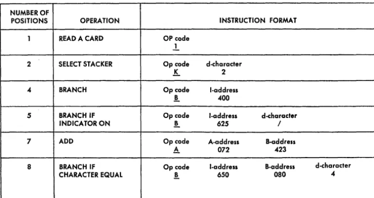
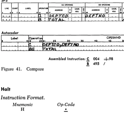
Examples of the six combinations possible in variable-length instructions are shown in Figure 12.
16
Instruction Descriptions
Specific instructions have been described in a standard format:
Title: This is the description of the instruction.
Instruction Format: This is the format of the par-ticular instruction described. The mnemonic operation
code used in the IBM 1401 Symbolic Programming
Sys-tem (SPS) is shown and the mnemonic for IBM 1401
Autocoder (A) is given, if it is diHerent from the SPS mnemonic.
Function: This is the function of the instruction.
Word Marks: This is the eHect of word marks with regard to data fields.
Timing: This is the formula to be used in calcu-lating the timing of the instruction. Key to abbrevia-tions used in formulas is shown in Figure 240.
Notes: These are special notations or additional in-formation that pertain to the operation.
Address Registers After Operation: The contents of the address registers are represented by the codes de~
scribed in the Chaining Instructions section.
Example: A practical application of the instruction is described and shown as labels for Autocoder and SPS (Symbolic Programming System) languages. With the label is the actual machine address in parentheses. It is not necessary for the programmer to know the actual address of a label when writing the program. The processor program assigns the actual address during the program assembly.
Assembled Instruction: This is the actual machine language instruction that is assembled by the Symbolic
Programming System or Autocoder processor programs
NUMBER OF
POSITIONS OPERATION INSTRUCTION FORMAT
1 READ A CARD OP code
.1
2 SELECT STACKER Op code d-character
!.. 2
'"
BRANCH Op code .! I-address 4005 BRANCH IF Op cade I-address d-character
INDICATOR ON .! 625 /
7 ADD Op code A-address B-address
A. 072 423
8 BRANCH IF Op code I-address B-address d-character
CHARACTER EQUAL ! 650 080
[image:19.620.61.445.64.267.2]'"
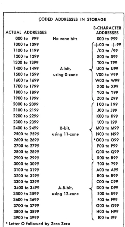
Addressing
Instructions and data to be used for processing in the 1401 are kept in core storage. Each position in storage is addressable (Figure 13). A field is defined by an eighth bit (called a word mark) and can contain either an instruction or data.
A data field is defined by a word mark in the high-order position. The units or low-high-order position of a data field is specified in the A- or B-address of the in-struction. The data field is read from right to left until a word mark in the high-order position is sensed.
An instruction is addressed by giving the high-order (operation code) position of the instruction. All opera-tion codes must have a word mark. (This word mark is normally set by the loading routine when the instruc-tions are loaded.) The machine reads an instruction
~ODED ADDRESSES IN STORAGE 3-CHARACTER
ACTUAL ADDRESSES ADDRESSES
000 to 999 No zone bits 000 to 999
1000 to 1099 =1=00 to =1=99
1100 to 1199 /00 to /99
1200 to 1299 500 to 599
1300 to 1399 TOO to T99
1400 to 1499 A-bit, UOO to U99
1500 to 1599 using O-zone VOO to V99
1600 to 1699 WOO to W99·
1700 to 1799 XOO to X99
1800 to 1899 YOO to Y99
1900 to 1999 ZOO to Z99
2000 to 2099 100 to 199
2100 to 2199 JOO to J99
2200 to 2299 KOO to K99
2300 to 2399 LOO to L99
2400 to 2499 B-bit, MOO to M99
2500 to 2599 using ll-zone NOO to N99
2600 to 2699 *000 to 099
2700 to 2799 POO to P99
2800 to 2899 QOO to Q99
2900 to 2999 ROO to R99
3000 to 3099 ?OO to ?99
3100 to 3199 AOO to A99
3200 to 3299 BOO to 899
3300 to 3399 COO to C99
3400 to 3499 A-B-bit, 000 to 099
3500 to 3599 using 12-zone EOO to E99
3600 to 3699 FOOto F99
3700 to 3799 GOO to G99
3800 to 3899 HOO to H99
3900 to 3999 100 to 199
* Letter 0 followed by Zero Zero
Figure 13. Core Storage Address Codes 18
from left to right until it senses the word mark asso-ciated with the next sequential instruction. The final instruction in the program must have a word mark set at the right of its low-order position.
Example: Instruction address 400 (Figure 14)
con-tains the operation code for the following instruction:
Op Code A-address B-address
~ 542 560
When this instruction is executed, the data in the A-field is added to the data in the B-field:
0025347 04601231 04626578 The result is stored in the B-field.
Input-Output Storage Assignments
Three areas of storage are reserved for input and out-put data. Storage positions 001 through 080, are reserved for the information from the 80 columns of the card. The second area of storage, positions 101 through 180, is reserved for assembling data to be punched. Positions 000 and 100 should not be used. Data stored in position 000 before a card read opera-tion is replaced by CAB bits at the end of the read operation. Data stored in position 100 before a punch
Instruction addressed by high-order position
STORAGE
400 401 402 403 404 405 406 407 (NSI)
ADDRESS
INSTRUCTION A 5 4 2 5 6 0 WM
Op code
The word mark associated with the next sequential in-struction (NSI) stops the reading of this inin-struction.
STORAGE ADDRESS 536 537 538 539 540
DATA 0 0 2 5 3
v
A-field
Word mark identifies high-order position of A-field.
STORAGE ADDRESS 553 554 555 556 557 558
DATA .Q. 4
t'
6 0 1
y
B-field
Word mark identifies high-order position of B-field.
Figure 14. Data and Instruction Addressing
2
A-address
~
541 542 543
4 7 !
B-address
t
559 560 561
[image:20.620.46.261.325.715.2]operation is replaced by C82 bits at the end of the punch operation. The third area of storage, positions 201 through 300 or 332, is reserved for assembling characters to be printed. Positions 81 through 99, and 181 through 200, are available for normal s'torage use. When the reserved areas are not being used as speci-fied, they can be used for other storage operations
(Figure 15).
Operation
of
IBM J40J RegistersThe IBM 1401 Data Processing System can operate on and process data to produce a desired result by execut-ing a series of instructions at high speed. A series of instructions designed to solve a problem is known as a program. Because these instructions are retained in core storage, it is more properly called a stored pro-gram.
The processing unit must interpret an instruction and perform the function prescribed by the instruction. In order to do this, various types of devices that are capable of receiving information, storing it, and trans-ferring it as directed by control circuits are used. These
devices are known as registers. The' 1401 has seven registers, four are address registers and three are character registers (Figure 16).
Address Registers
There are three address registers in the IBM 1401 Proc-essing Unit. One controls program sequence, and the other two control the transfer of data from one storage location to another.
I-Address Register. The I- (Instruction) address reg-ister always contains the storage location of the next instruction character to be used by the stored pro-gram. The number in this register is increased by one as the instruction is read from left to right.
A-Address Register. The A-address register normally contains the storage address of the data in the A-address portion of an instruction. Normally, as the instruction is executed, the number in this register is decreased by 1 after each storage cycle that involves the A-address.
APPLICATlON _ _ _ _ _ _ _ _ _ _ _ _ _ _ _ _ _ _ _ _ _ _ _ DATE _ _ _ _
"01 80
.00101 180
291
"'
•
•
+ ' Storage Core
r----o
Register B.
Register Ar--+
•
-Storage Op
Address
.
RegisterRegister
t
t
,I-Address A-Address B-Address
Register Register Register
1 ...
f
t
Figure 16. IBM 1401 Processing Unit Registers
Note: If the A-address portion of the instruction does not contain a 1401 storage address (for exam-ple
%
Ux) the contents of the A-=address register are not disturbed as the instruction is executed.B-Address Register. This register normally contains
the storage location of the data in the B-address por-tion of an instrucpor-tion. Normally, as a storage cycle involving the B-address is executed, the storage address in the B-address register is decreased by 1.
Character Registers
The A- and B-character registers and the Op-register are single-character registers used to store data during the execution of an instruction.
Op-Register. The Op- (Operation) register stores the
operation code of the instruction in process for the duration of the operation. The operation code is stored in BCD code including the check bit, but excluding the word mark.
B-Register. Each character leaving 1401 core storage
enters the B-register. The character is stored in 8-bit form (BCD code, check bit, and word mark). The B-register is reset and filled with a character from core storage on every storage cycle.
A-Register. The A-register is reset and filled with the
character from the B-register during each storage cycle that involves the A-address, and during all
20
instruction cycles except the first and last 1- (In-struction) cycle of each instruction. Data is stored in 8-bit form.
Note: Information can be written back into core storage directly from either the A- or B-register .
Figure 17 shows the I-phase of an operation and gives a detailed schematic for loading a 7 -character instruction in the operation code register, in the A- and B-registers and in the 1-, A-, and B-address registers. Eight storage cycles are required to load the complete instruction in the register. Each stor-age cycle requires .0115 millisecond.
Note: The A- and B-address registers contain
3-character addresses. Actual addresses are shown in this schematic because the storage display lights on the console show 4-digit addresses.
Chaining Instructions
In some' programs, it becomes possible to perform a series of operations on several fields that are in con-secutive storage locations. Some of the basic opera-tions, such as ADD, SUBTRACf, MOVE, and LOAD, have the ability to be chained so that less time is required to perform the operations, and space is saved in storing instructions. Here is an example of the chaining tech-nique: assume that four 5-position fields stored in sequence are to be added to four other sequential fields. This operation could be done using four 7-character instructions:
A 700 850
A 695 845
A 690 840
A 685 835
At the completion of the first instruction, the A-address register contains 695 and the B-A-address register contains 845. These are the same numbers that are in the A- and B-addresses in the second instruction. Eighty storage cycles would be required to execute these instructions, thus using up .920 millisecond. Also, 28 storage positions are required to store these in-structions.
By taking advantage of the fact that the A- and B-address registers contain the necessary information to perform the next instruction, this same sequence of operations can be executed as follows:
A
700 850A A A
CYCLE OPERATION
I-Op The operation code enters the B-register and the Op-register.
1-1
1-2
1-3
1-4
1-5
1-6
1-7
Because this is the first I-cycle, the A-register is undisturbed.
The A-address register is reset to blanks during the first part of the cycle for all instructions. The B-address register is reset to blanks during the first part of the cycle for all operations except Move, Load, Store A- and Store B-address Register opera-tion. During the 1-1 cycle, the second instruction character (first character of the A-address) enters the thousands and hundreds positions of the A- and B-add~ess registers and the A-register by the way of the B-register.
The third character of the instruction enters the tens posi-tion of the A- and B-address registers, and the A-register through the B-register.
The fourth instruction character enters the units position of the A- and B-address registers, and the A-register through the B-register.
The B-address register is reset at the beginning of this cycle. The fifth instruction character (first character of the B-address) enters the hundreds position of the B-address register, and the A-register through the B-register.
The sixth instruction character goes to the tens position of the address register, and the A-register through the B-register.
The seventh character of the instruction (last character of the B-address) enters the units position of the B-address register and the A-register through the B-register.
The first character of the next instruction enters the B-register only. Because this is the last I-cycle for this
instruc-tion, the A-register and the Op-register, the A- and
B-address registers are undisturbed. The detection of a word mark associated with this character signals the ma-chine that this is the Op code for the next instruction. The loading operations stops, and the instruction that was just loaded is executed. Note that the I-address register con-tains the address of the high-order position of the next sequential instruction.
Figure 17. Schematic of Instruction Loading
Instruction
l
AI
5I
6I
7 1 T 1 1 1 2 1 SI
Location 119711981199120012011202120312041
I Register B Register A Register
101119171
[A]
W
Cycle 1OP Register A Address Register B Address Register
~ 111111111
I
11111111I Register B Register A Register
IOPI9181
o
o
Cycle 2OP Register A Address Register B Address R~gister
[A]
10(51 blbl
IOI51,bOlb,1I Register B Register A Register
101119 191
o
GJ
Cycle 3OP Register A Address Register B Address Register
W
1015161bl
10 1516 1 b 1I Register B Register A Register
I °121°1° 1
[?J
[2l
Cycle 4OP Register A Address Register B Address Register
fI]
101516171 10(516171I Register B Register A Register
\ °121°11 1
[!J
[!]
Cycle 5OP Register A Address Register B Address Register
101516171 11131bl b
I
I Regisler B Register A Register
\ 0(21 0121
[i]
GJ
Cycle 6OP Register A Address Register B Address Register
1113,1, b
I
I Regisler B Register A Register
I
°121°13I
~
o
Cycle 7OP Register A Address Register B Address Register
1°1516171 /1
131112 1
I Register B Register A Register
1°12,0 (4\
[I]
o
Cycle 8OP Register A Address Register B Address Register
the A- and B-addresses. The following three instruc-tions contain only the operation code for those instructions. The A- and B-addresses are the results left in the A- and B-address registers from the previous instruction. This type of operation requires 62 storage cycles, and takes .713 ms to execute. Storage of these chained instructions requires only ten storage positions. The ability to chain a series of instructions does not depend on the use of the same operation code. Chained instructions may have various Op codes. To be oper-ated on, the A-fields must be in sequence, and the B-fields must be in sequence. Example:
A 900 850
M A M
For example, assume that the data fields are each ten characters long:
The ten characters at location 900 were added to 850. The ten characters at location 890 were moved to 840. The ten characters at location 880 were added to 830. The ten characters at location 870 were moved to 820.
The description of each instruction includes the con-tents of the address registers after the operation has been performed. Figure 18 shows the abbreviations that indicate the contents of these registers.
By using this information, the programmer can de-termine the status of the registers and decide whether chaining is practical in specific cases.
Note: Instructions that contain other than IBM 1401
storage addresses cannot be chained. For example, M
%
u
x xxx R is a tape read instruction. The tape unit is signaled as the machine reads the instruction. Al-though the A-address register contains%4x
after the operation, chaining is impossible because the machine does not select the unit from the contents of the A-address register.Most single-address instructions (Op code and an A-address) cause the A-address to be. inserted in both the A- and B-address registers (for example ~ xxx). However, MOVE, LOAD, and STORE A-or STORE B-ADDRESS
REGISTER (Op codes M, L, Q, and H) do not disturb the
22
B-address register, and therefore permit the program-mer to use theprevious contents of that register as part of the instruction.
All no-address instructions (Op code only) use the previous contents of the A- and B-address registers.
The contents of the B-address register after a branch instruction (Op code and I-address) depend on whether or not the indexing feature is installed in the 1401: 1. With the indexing feature installed, the B-address
register contains the address of the next sequential instruction if a branch occurs.
2. Without the indexing feature installed, the B-address register is cleared to blanks whenever a branch occurs.
ABBREVIATION MEANING
A A-address of the instruction
B B-address of the instruction
NSI Address of the next sequential instruction
BI Address of the next instruction if a branch occurs
LA The number of characters in the A-field
LB The number of characters in the B-field
Ln The number of characters in a disk record
Lw The number of characters in the A- or B-field,
whichever is smaller
Ap The previous setting of the A-address register
Bp The previous setting of the B-address register
dpp The d-character and the tens and units positions
of the previous register setting
dbi The d-character and the tens and units positions
of the branch instruction
dbb The d-character and blank in the units and tens
position
IBM 1401 Programming Systems
The 1401 Symbolic Programming System and 1401
Autocoder are the basic symbolic programming aids
for IBM 1401 Data Processing Systems. Each consists of a set of language specifications and a processor program. The language is used to write the source program, and the processor program translates the symbolic language program (the source program) into the actual machine language program (obiect pro-gram).
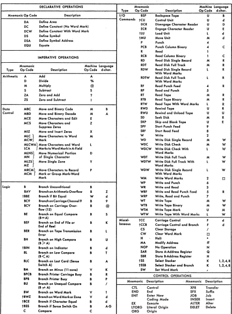
Symbolic Languages
Both the Autocoder and SPS languages permit the pro-grammer to define areas, write instructions, and exer-cise some control over the execution of the processor program by writing symbolic statements. These state-ments are written using mnemonic operation codes (Figures 19 and 20) and the symbolic names with which the programmer names data, instructions, and work areas. For example, a symbolic instruction to add the data in a field called WHT AX to the data in a field called TOTDED would be written A WHTAX TOTDED in symbolic language.
Area Definition (Declarative Operations)
The area-definition entries are used to assign sections of storage for fixed data (constants) that will be needed during processing, to set aside work areas, and to as-sign symbolic names to data and devices used in the program. Area-definition statements are examined by the processor program during assembly of the object program. Some produce constants (cards that are loaded with the object program), but none produce instructions to be executed in the object program.
Instructions (Imperative Operations)
The instruction entries state symbolically the proce-dure to be taken during execution of the object pro-gram. They are actual commands to the object machine such as ADD, SUBTRACT, READ, PUNCH, etc.
Processor Control Operations
These are special instructions given by the program-mer to the processor program. They exercise such control as: where to begin assigning storage for the object program, where the program ends, how much storage is available in the object-machine, etc. Proc-essor control statements are never executed as instruc-tions in the object program. They are used only during object-program assembly.
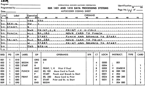
IBM 1401 Symbolic Programming System (SPS)
The SPS system is essentially a one-for-one coding system in which one symbolic statement is written for each instruction that appears in the object program. Two versions of the SPS are available. SPS-1 operates on a 1401 with 1400 positions of core storage, an IBM 1402 Card Read-Punch, and an IBM 1403 Printer, but it can assemble programs for any object-machine with as many as 4,000 positions of core-storage. SPS-2 can assemble programs for any 1401 system (1400 to 16,000 positions of core storage), but must assemble the program in a 1401 system with at least 4,000 posi-tions of core-storage, the IBM 1402 Card Read-Punch, and an IBM 1403 Printer.
An SPS source program must be coded on the 1401 Symbolic Programming System Coding Sheet (form X24-1152). This coding sheet is designed for fixed-form coding. (A special area is reserved for each item to be contained in an SPS statement.)
A complete description of the 1401 SPS is contained in the IBM 1401 Data Processing System Bulletin, IBM 1401 Symbolic Programming System, Preliminary Spec-ifications (form }24-0200).
A sample SPS program is shown in Figure 21.
IBM 1401 Autocoder
The 1401 Autocoder is a more powerful symbolic pro-gramming system for the IBM 1401 Data Processing System. This system provides a macro facility that permits the user to call out standard sets of instruc-tions (routines) from a library stored on magnetic tape.
It also permits him to code literals (actual data to be operated on during processing) directly in the instruc-tions that use them, thus simplifying the area-definition part of the source program.
The 1401 Autocoder system can be used to assemble programs for all IBM 1401 Data Processing Systems. However, the machine used to assemble an Autocoder program must have at least:
4,000 positions of core storage
Four IBM 729 II, 729 IV, 729 V, or 7330 Magnetic Tape Units
IBM 1403 Printer, Model 2
IBM 1402 Card Read-Punch
Advanced-Programming Features High-Low-Equal Compare Feature Sense Switches
AREA DEFINITION
Mnemonic
Description Operation Code
DCW Define Constant With Word Mark
DC Define Constant (No Word Mark)
DS Define Symbol
DSA Define Symbol Address
INSTRUCTIONS
Type Mnemonic Description Machine Language
Operation Code Equivalent
A Add A
S Subtract S
*M Multiply @
Arithmetic *D Divide %
ZA Zero and Add ? (Prints as &)
ZS Zero and Subtract I (Prints as -)
MCW Move Characters to A or B Word Mark M
*MCM Move Characters to Record or Group Mark P
MCS Move Characters and Suppress Zeros Z
MN Move Numeric D
MZ Move Zone Y
MCE Move Characters and Edit E
Data Control LCA Load Characters to A Word Mark L
SW Set Word Mark ,
CW Clear Word Mark 0
CS Clear Storage I
*MIZ Move and Insert Zeros (for reading 7070 Compressed Tape) X
*MA Modify Address #
*SAR Store A Address Register Q
*SBR Store B Address Register H
B Branch B
BWZ Branch if Word Mark and/or Zone V
Logic Control C Compare C
NOP No Operation N
H Halt
*BBE Branch if Bit Equal W
R Read a Card 1
W Write a Line 2
WR Write and Read 3
P Punch a Line
..
RP Read and Punch 5
WP Write and Punch 6
System Control WRP Write, Read and Punch 7
*SRF Start Read Feed 8
*SPF Start Punch Feed 9
SS Select Stacker K
CC Control Carriage F
CU Control Unit U
MU Move Unit M
LU Load Unit L
PROCESSOR CONTROL OPERATIONS
Mnemonic Description
Operation Code
cn Control
ORG Origin
END End
EX Execute
*Pertains to an optional feature.
Figure 19. IBM 1401 Symbolic Programming System Mnemonics
DEC LARA TlVE OPERATIONS Mnemonic Machine Language
Type Op Code Description OpCode d-char.
Mnemonic Op Code Description I/O BSP Backspace Tape U B
Define Area Commands tCU Control Unit U d
DA
DC Define Constant (No Word Mark) OCR Disengage Character Reader U 0
ECR Engage Character Reader U E
DCW Define Constant With Word Mark
tLU Load Unit L d
OS Define Symbol
tMU Move Unit M d
DSA Define Symbol Address
P Punch 4
EQU Equate PCB Punch Column Binary 4 C
R Read 1
IMPERATIVE OPERATIONS RCB Read Column Binary 1 C
RD Read Disk Single Record M R
Mnemonic Machine Language ROT Read Disk Full Track M R
Type Op Code Description OpCode d-char. ROW Read Disk Single Record L R
With Word Marks
Arithmetic A Add A RDTW Read Disk Full Track L R
0 Divide % With Word Marks
M Multiply @ RF Read Punch Feed 4 R
S Subtract S RP Read and Punch 5
ZA Zero and Add ? RT Read Tape M R
ZS Zero and Subtract I RTB Read Tape Binary M R
RTW Read Tape With Word Marks L R
Data MBC Move and Binary Code M B RWD Rewind Tape U R
Control MBD Move and Binary Decode M A RWU Rewind and Unload Tape U U
MCE Move Characters and Edit E SO Seek Disk M R
MCS Move Characters and Z SKP Skip and Blank Tape U E
Suppress Zeros SPF Start Punch Feed 9
MIZ Move and Insert Zeros X SRF Start Read Feed 8
MLC} Move Characters to Word M W Write 2
MCW Mark WD Write Disk Single Record M W
MLCWA} Move Characters and Word L WDC Write Disk Check M W
LCA Marks to Word Mark in A-Field WDCW Write Disk Check With L W
MLNS} Move Numerical Portion 0 Word Marks
MN of Single Character WDT Write Disk Full Track M W
MLZS} Move Single Zone Y WDTW Write Disk Full Track With L W
MZ Word Marks
MRCM} Move Characters to Record P WOW Write Disk Single Record L W
MCM Mark or Group Mark-Word With Word Marks
Mark WM Write Word Marks 2 0
WP Write and Punch 6
Logic B Branch Unconditional B WR Write and Read 3
BAV Branch on Arithmetic Overflow B Z WRF Write and Read Punch Feed 5 R
tBBE Branch if Bit Equal W d WRP Write, Read and Punch 7
BC9 Branch on Carriage Channel9 B 9 WT Write Tape M W
BCV Branch on Carriage Over- B @ WTB Write Tape Binary M W
flow (12) WTM Write Tape Mark U M
BE Branch on Equal Compare B S WTW Write Tape With Word Marks L W
(B=A)
Miscel· tcc Carriage Control F d
BEF Branch on End of File or B K laneous
tCCB Carriage Control and Branch F d
End of Reel
BER Branch on Tape Transmission B L CS Clear Storage /
Error CW Clear Word Mark 0
BH Branch on High Compare B U H Halt
.
(B>A) MA Modify Address #
tBIN Branch on Indicator B d NOP No Operation N
BL Branch on Low Compare B T SAR Store A-Address Register Q
(B<A) SBR Store B-Address Register H
BLC Branch on Last Card (Sense B A tSS Select Stacker K 1,2,4,8
Switch A) tSSB Select Stacker and Branch K 1,2,4,8
BM Branch on Minus (ll-zone) V K SW Set Word Mark ,
BPCB Branch Printer Carriage Busy B R CONTROL OPERATIONS
BPB Branch Printer Busy B P
Mnemonic Descriptian . Mnemonic Description
BU Branch on Unequal Compare B /
(B -# A) CTL Control XFR Transfer
BW Branch on Word Mark V 1 END End SFX Suffix
tBWZ Branch on Word Mark or Zone V d ENT Enter New JOB Job
tBCE Branch if Character Equal B d EX Coding Mode Execute ALTER INSER Insert Alter
tBSS Branch if Sense Switch On B A-G LTORG Literal Origin DELET Delete
C Compare C ORG Origin
t d-Character must be placed in operand when coding in AulococI.r.
[image:27.612.65.543.64.709.2]IB~
1401
Symbolic Programming System Coding SheetProgram _ _ _ _ _ _ _ _ _ _ _ _ _
Programmed by _ _ _ _ _ _ _ _ _ _ Date _ _ _ _
(AI OPERAND (BIOPERAND LINE COUNT LABEL OPERATION CHAR. ~ CHAR.
ADDRESS ADDRESS g d
Page No.
W
of-Identification ~' 7 .... 6 '--'---'---'-;:;' 8--'0'
COMMENTS
3 5 6 7 8 13 14 16 17
I;J
ADJ. 27 28I~I
ADJ. 38 39 40 55 0 I 0 o RIG 101)0 0,0 2 0 BEG'IN SWI 0,0,0,1 o 3 0 S,T A R,"[' R I
0 4 0 8W:2 Ip R ',N,T 000 1 IK P R ',N T I f: X-COL. 1 0 5 0 Ip,u N C H iM C:W 10 0,8,0 101,8,0 MV C,A,RD r,o P,V N c: H
o 6 0 P I Is T,A R,. PNc:II-9R. TO S,T A,R, ,"T
o 7 0 Ip,R. , ,N,T IMC:W 0 0 8 0 02,8 0 M,V C,A,R-,t) T 0 PR "N,I
o 8 0 Iw, I S T /t.,R,T P ,R,N,T - S,k' ,"-,0 S,T A,R.,T
o 9 0 e:N~t) BE:& IN
I o 0
:
Assembled
Assigned
Machine-Line Op d- Storage Language
Page No. Count Label Code (A) Operand (B) Operand Char. Locations I nstructio ns Comments
1 010 ORG 0500
1 020 4 Begin SW 0001 0500 , 001
1 030 1 Start R 0504 1
1 040 8 BWZ Print 0001 K 0505 V 524 001 K Print if X-Col 1
1 050 7 Punc