64410-90903 E0688
ADVANCED INTEGRATION ENVIRONMENT
HP 64410 Emulation:
68020 Emulator Operating Manual
68020 Emulation:
Operating Manual
Ff/~ HEWLETT
Notice
Hewlett-Packard makes no warranty of any kind with regard to this material, including, but not limited to, the im-plied warranties of merchantability and fitness for a par· ticular purpose. Hewlett-Packard shall not be liable for errors contained herein or for incidental or consequential damages in connection with the furnishing, performance, or use of this material.
Hewlett-Packard assumes no responsibility for the use or reliability of its software on equipment that is not furnished by Hewlett-Packard.
©Copyright 1987,1988 Hewlett-Packard Company.
This document contains proprietary information, which is protected by copyright. All rights are reserved. No part of this document may be photocopied, reproduced or translated to
another language without the prior written consent ofHewlett-Packard Company. The information contained in this document is subject to change without notice.
HP and HP-UX are trademarks of Hewlett-Packard Company.
Torx is a registered trademark of the Camcor division of Textron, Inc.
UNIX is a registered trademark of AT&T.
Logic Systems Division 8245 North Union Boulevard
Printing History
New editions are complete revisions of the manual. Update pack-ages, which are issued between editions, contain additional and replacement pages to be merged into the manual by the customer. The dates on the title page change only when a new edition or a new update is published. No information is incorporated into a reprinting unless it appears as a prior update; the edition does not change when as update is incorporated.
A software code may be printed before the date; this indicates the version level of the software product at the time the manual or up-date was issued. Many product upup-dates and fixes do not require manual changes and, conversely, manual corrections may be done without accompanying product changes. Therefore, do not expect a one to one correspondence between product updates and manual updates.
Certification and Warranty
Certification
Warranty
Hewlett-Packard Company certifies that this product met its published specifications at the time of shipment from the factory. Hewlett-Packard further certifies that its calibration measure-ments are traceable to the United States National Bureau of Standards, to the extent allowed by the Bureau's calibration facility, and to the calibration facilities of other International Standards Organization members.
This Hewlett-Packard system product is warranted against defects in materials and workmanship for a period of 90 days from date of installation. During the warranty period, HP will, at its op-tion, either repair or replace products which prove to be defective.
Warranty service of this product will be performed at Buyer's facility at no charge within HP service travel areas. Outside HP service travel areas, warranty service will be performed at Buyer's facility only upon HP's prior agreement and Buyer shall pay HP's round trip travel expenses. In all other cases, products must be returned to a service facility designated by HP.
Limitation of
Warranty
Exclusive Remedies
designated by HP for use with an instrument will execute its programming instructions when properly installed on that instru-ment. HP does not warrant that the operation of the instrument, or software, or firmware will be uninterrupted or error free.
The foregoing warranty shall not apply to defects resulting from improper or inadequate maintenance by Buyer, Buyer-supplied software or interfacing, unauthorized modification or misuse, operation outside of the environment specifications for the product, or improper site preparation or maintenance.
No other warranty is expressed or implied. HP specifically disclaims the implied warranties of merchantability and fit-ness for a particular purpose.
The remedies provided herein are buyer's sole and ex-clusive remedies. HP shall not be liable for any direct, in-direct, special, incidental, or consequential damages, whether based on contract, tort, or any other legal theory.
Product maintenance agreements and other customer assistance agreements are available for Hewlett-Packard products.
Radio Frequency Interference
What is Radio
Frequency
Interference?
All types of electronic equipment are potential sources of uninten-tional electromagnetic radiation which may cause interference with licensed communication services. Products which utilize digital waveforms such as any computing device are particularly characteristic of this phenomena and use of these products may re-quire that special care be taken to ensure that Electromagnetic In-terference (EMI) is controlled. Various government agencies regu-late the levels of unintentional spurious radiation which may be generated by electronic equipment. The operator of this product should be familiar with the specific regulatory requirement in ef-fect in his locality.
Reducing the Risk
Of EMI
a. Ensure that the top cover of the ICC or LDSCC is properly installed and that all screws are tight (do not over tighten).
b. When using a feature set which includes cables that egress from the chassis slot of the ICC or LSDCC, en-sure that the knurled nuts and ferrels, or brackets that ground the cable shields are clean and tight (Do not overtighten). The EEPROM Programmer cable has an exposed shield that must make contact with the cable clamp.
c. During times ofinfrequent use, disconnect the EEPROM Programmer and cables from the card cage and the target system.
d. Use only shielded coaxial cables on the four external BNC connectors on the rear of the ICC.
e. Use only the shielded IMB cable supplied with the ICC or LSDCC for connection to additional ICC's or LSDCC's.
Manufacturer's
Declarations
U.S.A. Federal Communications Commission
a. If possible, increase the distance between the ICC or LDSCC and the susceptible equipment.
b. Rearrange the orientation of the chassis and cables of the ICC system or LDSCC.
c. Plug the ICC or LDSCC into a separate power outlet from the one used by the susceptible equipment (the two outlets should be on different electrical circuits).
d. Plug the ICC or LDSCC into a separate isolation trans-former or power line filter.
You may need to contact your local Hewlett-Packard sales office for additional suggestions. Also, the U.S.A. Federal Communica-tions Commission has prepared a booklet entitled How to Identify
and Resolve Radio - TV Interference Problems which may be help-ful to you. This booklet (stock #004-000-00345-4) may be pur-chased from the Superintendent of Documents, U.S. Government Printing Office, Washington, D.C. 20402U.S.A.
Federal Republic of Germany
Japan
area is likely to cause interference in which case the user at his own expense will be required to take whatever measures may be required to correct the interference.
Hiermit wird bescheinigt, daB dieses Gerates in
Ubereinstimmung mit den Bestimmungen der FTZ 1046/1984 funkentstort ist. Der Deutschen Bundespost wurde das In-verkehrbringen dieses Gerates angezeigt und die Berechtingung zur Uberprlliung der Serie aufEinhaltung der Bestimmungen eingeraumt.
c.
O"J ~ tWl ,l, ~ - ti{~*~ti (
rffi
.I~tth
t.gt 1: ~ ~ 1-c
I~ ffl ~n
~ r< ~ ·~~ ~~ ~ ~)~~I•~~~O"J~~-~~~~§~tL~ffi~~~~~~•a•~~~m~
~ t,l ~ ( V C C I ) ~
*
IC ii~l
-C ~ ~ 1:To
Safety
Summary of Safe
Procedures
Ground The Instrument
Do Not Operate In An Explosive Atmosphere
Keep Away From Live Circuits
The following general safety precautions must be observed during all phases of operation, service, and repair of this instrument. Failure to comply with these precautions or with specific warn-ings elsewhere in this manual violates safety standards of design, manufacture, and intended use of the instrument. Hewlett-Pack-ard Company assumes no liability for the customer's failure to comply with these requirements.
To minimize shock hazard, the instrument chassis and cabinet must be connected to an electrical ground. The instrument is equipped with a three-conductor ac power cable. The power cable must either be plugged into an approved three-contact electrical outlet or used with a three-contact to two-contact adapter with the grounding wire (green) firmly connected to an electrical ground (safety ground) at the power outlet. The power jack and mating plug of the power cable meet International Electro technical Com-mission (IEC) safety standards.
Do not operate the instrument in the presence of flammable gases or fumes. Operation of any electrical instrument in such an en-vironment constitutes a definite safety hazard.
Do Not Service Or Adjust Alone
Do Not Substitute Parts Or Modify Instrument
Dangerous Procedure Warnings
Warning
the power cable connected. Under certain conditions, dangerous voltages may exist even with the power cable removed. To avoid injuries, always disconnect power and discharge circuits before touching them.
Do not attempt internal service or adjustment unless another per-son, capable of rendering first aid and resuscitation, is present.
Because of the danger ofintroducing additional hazards, do not in-stall substitute parts or perform any unauthorized modification of the instrument. Return the instrument to a Hewlett-Packard Sales and Service Office for service and repair to ensure that safety features are maintained.
Warnings, such as the example below, precede potentially dangerous procedures throughout this manual. Instructions con-tained in the warnings must be followed.
Instruction manual symbol: the product is marked with this sym-bol when it is necessary for the user to refer to the instruction manual in order to protect against damage to the instrument.
Indicates dangerous voltage (terminals fed from the interior by voltage exceeding 1000 volts must be marked with this symbol).
Protective conductor terminal. For protection against electrical shock in case of a fault. Used with field wiring terminals to indi-cate the terminal which must be connected to ground before operating the equipment.
Low-noise or noiseless, clean ground (earth) terminal. Used for a signal common, as well as providing protection against electrical shock in case of a fault. A terminal marked with this symbol must be connected to ground in the manner described in the installation (operating) manual before operating the equipment.
Frame or chassis terminal. A connection to the frame (chassis) of the equipment which normally includes all exposed metal struc-tures.
Alternating current (power line).
Direct current (power line).
Note
Caution
I
Warning
G
The Note sign denotes important information. It calls your atten-tion to a procedure, practice, condition, or similar situation which is essential to highlight.
The Caution sign denotes a hazard. It calls your attention to an operating procedure, practice, condition, or similar situa-tion, which, if not correctly performed or adhered to, could result in damage to or destruction of part or all of the product.
Notice
Caution
•
CONDUCTIVE FOAM OR PLASTIC OVER EMULATOR PINS MAY CAUSE ERRATIC OPERATION.The emulator and preprocessor user assembly pins are covered at the time of shipment with either a conductive foam wafer or a con-ductive plastic pin protector. This is done for two reasons:
1) to protect the user interface circuitry within the emulator or preprocessor from electro-static discharge (ESD),
2) to protect the delicate gold plated pins of the probe assemb-ly from damage due to impact.
Both the foam and plastic protection devices are conductive. This may cause erratic performance of the emulation or analysis sys-tem during operation, and also during option_ test performance verification. Therefore, it is recommended that the foam or plastic device be removed before using the emulation or analysis system or before running option_test performance verification.
USING THIS MANUAL
Organization
Chapter 1
Chapter 2
Chapter 3
Chapter 4
lntrcxlucingThe68020 Emulator contains a brief description of the 68020 emulator.
Installing Emulation Hardware contains information on stalling your 68020 emulation system hardware into the in-strumentation cardcage and making a measurement system. This chapter also contains information on connecting the emulator to your target system.
Getting Started steps you through the emulation process from creating an example program to performing measurements on the execution of that program in emulation.
The Getting Started chapter discusses preparing your program modules and the.files that are generated by assembling, compil-ing, and linking programs. See the appropriate cross
as-sembler/linker and compiler manuals for more detailed informa-tion on preparing program modules for emulainforma-tion.
con-Chapter 5
Chapter 6
Chapter 7
<:;hapter 8
Chapter 9
figuring the emulator, and shows how to load configuration com-mand files from a previous emulation session.
Using The Emulator provides guidelines for using the emulator with a target system and provides information you need to know about how the emulator interacts with your target system.
The Emulation Monitor Program provides a detailed descrip-tion of the emuladescrip-tion monitor program and how to modify it for your system requirements.
Using Custom Coprocessors describes how to make a custom coprocessor register format file and how to modify the emulation monitor so that your emulation system can display and modify coprocessor registers.
Using Simulated 1/0 And Simulated Interrupts describes how to set up your emulator to use host 1/0 resources to simulated target system IJO and how to use the simulated interrupt features of the emulator. .
Appendix B
Appendix C
Understanding
The Examples
provide listings of the demonstration programs used in this manual as a reference for you when working through the the ex-amples.
Timing Comparisons lists timing comparisons between 68020 processors and the HP 64410 Emulator.
This manual assumes that you are using the User-Friendly Inter-face Software (HP 64808S) which is activated by executing the HP 64000-UX pmon command. This means that the manual will show you how to enter HP 64000-UX system commands (edit, compile, assemble, link, msinit, msconfig, etc.) by telling you to press various softkeys.
If you are not using "pmon", you will find the USER INTER-F ACE/HP-UX CROSS REINTER-FERENCE appendix of the 68020
Emulation Reference Manual especially useful. The cross
reference table shows you how the "pmon" softkeys translate into commands that can be entered from the HP-UX prompt.
The examples provided throughout this manual use the following structure:
PRESS edit module.S
PRESS or press
edit
module.S
templates are available at the HP 64000 system monitor level.
this is the name of a file which you must type in. Softkeys are not provided for this type of selection since it is variable. However, a softkey prompt such as
<FILE> will appear as a softkey selec-tion.
Contents
Chapter 1
Introducing The 68020 EmulatorOverview ... 1-1 Safety Considerations ... 1-1 Emulator Description ... 1-2 Manual Coverage ... 1-3
Chapter 2
Installing Your EmulatorOverview ... 2-1 Introduction ... 2-1 Safety Considerations ... 2-3 Preinstallation Inspection ... 2-4 Installing Your Emulation System Hardware ... 2-5 Installation Instructions ... 2-5
fil
Installing The Emulation Probe Into The Target System ... 2-10 Install Software ... · ... 2-13 Installing 68020 Emulation Software Updates ... 2-13 Turning On The HP 64120A ... 2-13Chapter 3
Getting Started
Overview . . . ... 3-1 Introduction ... 3-1 Emulation System Used For Examples ... 3-2 Making A Subdirectory For Your 68020 Project ... 3-2 Initializing And Configuring Your Measurement System .... 3-4 Preparing Your Program Modules ... 3-7
Copying The Demonstration Programs To Your
Chapter 4
Answering Emulation Configuration Questions
Overview ... 4-1 Introduction ... 4-1 Running Emulation ... 4-2 Modifying The Configuration File ... 4-3 Selecting Real-Time/ Nonreal-Time Run Mode ... 4-3 Enabling Emulator Monitor Functions ... 4-5 Resetting Into The Monitor ... 4-6 Enabling Emulator Use of Software Breakpoints ... 4-7 Selecting The Software Breakpoint Instruction Number .. 4-7 Enabling The Internal 68881 FPU ... 4-8 Specifying The FPU Coprocessor ID ... 4-9 Using Custom Coprocessors ... 4-9 Specifying The Custom Coprocessor File ... .4-10 Modifying a Memory Configuration ... 4-10 Modifying The Emulation Pod Configuration ... 4-26 Configuring Simulated 1/0 ... 4-31 Configuring Simulated Interrupts ... 4-32 Naming The Configuration File ... .4-32 Configuration Switch ... 4-33 Cl ... 4-33 C2 (DSACKO) And C3 (DSACKl) ... .4-35
Chapter 5
Using The Emulator
Overview ... 5-1 Installing 68020 Emulation Software Updates ... 5-2 Emulation And Target System Dsack Signals ... 5-2
Interlocking Emulation Memory DSACK and Target
DSACK Signals ... 5-2
DSACK Signal Problems In Target Systems ... 5-4 Using The Vector Base Register ... 5-6 Using The Internal 68020 Cache ... 5-7 Cache Control ... 5-7 Analysis with Cache ... 5-8 Using Breakpoints With Cache Enabled ... 5-8 Using Function Codes For Displaying And Modifying Reserved
Address Space ... 5-10 Enabling/disabling BERR ... 5-11 UsingDMA ... 5-12 Using The Run From ... Until Command ... 5-16 UsingThe Emulation Monitor ... 5-18 Loading the Emulation Monitor ... 5-18 Resetting Into The Monitor ... 5-20 Systems With Memory Management Units (MMU's) ... 5-22 Memory Access Timing Issues ... 5-23 Loading An Absolute File ... 5-24 , If All Else Fails ... 5-26
Chapter 6
The Emulation Monitor Program
Sending Messages From the User Program To the Emulator Display ... 6-12 Emulation Monitor Memory Requirements For The 68020 .. 6-14 Linking The Emulation Monitor ... 6-15 Loading The Emulation Monitor ... 6-15 Emulation Monitor Flowchart ... 6-17
Chapter 7
Using Custom Coprocessors
Overview ... 7-1 Introduction ... 7-2 The Custom Register Format File ... 7-3 Address specification ... 7-4 Size Specification ... 7-4 Name Specification ... 7 -4 Register Set Display Specification ... 7 -5 Using the Internal FPU ... 7-5 Emulation Monitor Changes ... 7-9 Defining a Coprocessor Register Buffer ... 7-9 Modifying The MON_ALT_BUFFER Table ... 7-10 Modifying The MON_ALT_REGISTERSTable ... 7-11 Writing Coprocessor Copy Routines ... 7 -11 Answering Emulation Coprocessor Configuration Questions 7-13
Chapter 8
Using Simulated 1/0 And Simulated lnterrrupts
Configuring Simulated I/O ... 8-1 Restrictions On Simulated I/O ... 8-3 Simulated Interrupts ... 8-4 How Does A Simulated Interrupt Function? ... 8-4 Simulated Interrupts Versus Real Interrupts ... 8-7 Simulated Interrupt Configuration ... 8-7 Modifying The Monitor To Use Simulated Interrupts ... 8-10
Chapter 9
How The Emulator Works
Overview ... 9-1 Introduction ... 9-2 Are You There Function? ... 9-3 The Run Command ... 9-4 Run From Command ... 9-4 Run Until Command ... 9-5 Run From ... Until Command ... 9-5 Software Breakpoints ... 9-7 Setting A Software Breakpoint . . . ... 9-7 Executing A Software Breakpoint ... 9-8 Executing A Run Command After Executing A Software
Appendix A
Appendix B
Displaying CPU Registers ... 9-19 Modifying The CPU Registers ... 9-20
Emulation Error Messages
68020 Emulation Error Messages . . . A-1 cannot break into monitor . . . A-1 monitor did not respond to exit request ... A-2 slow dev at a= XX.XX (YY) . . . . . . . . A-3 no memory cycles . . . A-4 (no DSACK) message in tracelist . . . A-4 running in monitor ... A-4 running . . . A-5 Reset (with capital "R'~ ... A-5 reset (with lower case "r") . . . A-5 Attempt to write guarded memory, addr
=
XXXX ... A-5 Attempt to read guarded memory, addr=
XXXX ... A-5 Could not enable breakpoint at address XXXX . . . A-5 Could not disable breakpoint at address XXXX ... A-6 No breakpoint exists at address XXXX . . . A-6Source Files For Getting Started Examples
Introduction ... B-1 Source File For towers.c . . . B-2 Source File For simint.c . . . B-9
Appendix C
Timing ComparisonsIllustrations
Figure 2-1. HP 64120A Instrumentation Cardcage Features . 2-2 Figure 2-2. Removing the Cardcage Access Cover ... 2-6 Figure 2-3. ABG Protective Plastic Cable Cover ... 2-8 Figure 2-4. Board Installation Into Cardcage ... 2-9 Figure 2-5. Installing Emulator Probe Into PGA Socket .... 2-12
Figure 3-1. Towers.k Linker Command File ... 3-11
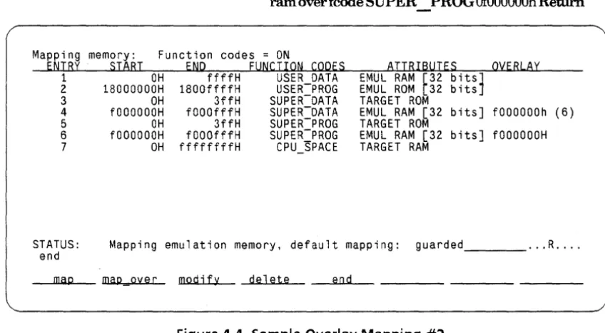
Figure 4-1. Default Memory Map Display ... 4-13 Figure 4-2. Overlay Addressing Within Physical Blocks .... 4-19 Figure 4-3. Sample Overlay Mapping #1 ... 4-20 Figure 4-4. Sample Overlay Mapping #2 ... 4-21 Figure 4-5. Setting Configuration Switches ... 4-34
Figure 5-1. Memory Access Timing, No DSACK Interlock ... 5-3 Figure 5-2. DMA Bus Request/Bus Grant Timing ... 5-12 Figure 5-3. Circuit For DMA Transfers ... 5-14 Figure 5-4. DMA Timing Diagram, DMA Disabled ... 5-15 Figure 5-5. Example Stack Frame ... 5-16
Figure 6-1. Monitor Message Routine ... 6-13
Figure 7-1. Sample Custom Register Specification File ... 7-6 Figure 7-1. Sample Custom Register Spec. File (Cont'd) ... 7-7 Figure 7-2. Custom Reg. Spec. Include File fpu_spec ... 7-7 Figure 7-3. Custom Reg. Spec. File Using Include Files ... 7-8
Figure 8-1. Simulated Interrupt Test Program ... 8-6
Figure 9-1. Monitor Operation At Start Of Transfer ... 9-13 Figure 9-2. Monitor Operation At End Of Transfer ... 9-14
1
Introducing The 68020 Emulator
Overview
Safety
Considerations
This chapter provides the following information:
• Safety considerations for your emulator
• A general description of your emulator
• What information is given in this manual
The HP 64000-UX Microprocessor Development Environment, along with the HP 64410SC/SD Emulation Subsystems, is a Class 1 instrument (provided with a protective earth terminal) and meets safety standard IEC 348, "Safety Requirements for
Electronic Measuring Apparatus". This Class I instrument meets Hewlett-Packard Safety Class I and has been shipped in a safe condition. Review both the instrument and the manual for safety markings and instructions before operation. Read and become familiar with the "Safety Summary", which follows the Certifica-tion/Warranty page of this manual, in addition to the items listed in chapter 2.
Emulator
Description
The HP 64410SC/SD Real-Time Emulator for 68020 microproces-sors is a powerful tool for both software and hardware designers. Using the HP 64410SC/SD Emulator's emulation memory (up to 512k bytes), software debugging can be done without functional target system memory. Measurements can be made using the emulator's internal 16.7 MHz clock or an external 25 MHz clock with no wait states.
Symbolic debugging lets you debug programs using the same symbols that you defined in your source code. You can control program flow using software breakpoints, single-stepping by op-code, and run-from and run-until commands.
The 68020 emulator has an internal 20 MHz MC68881 Floating Point Coprocessor. You can use this internal coprocessor or an ex-ternal coprocessor in your target system. The MC68881 instruc-tions can be disassembled in trace displays. You can also display and modify the floating point coprocessor registers.
Dual-ported memory allows you to display or modify emulation memory without halting the processor.
Flexible memory mapping lets you define address ranges referencing emulation memory or target system memory in 256-byte blocks. Blocks can be defined as emulation, target, guarded access, RAM, or ROM over the entire 4 Gbyte address range of the 68020. Since the 68020 supports devices with different memory widths on the data bus, each emulation memory block can be defined as 8, 16, or 32bits wide.
Manual Coverage
Analysis functions include trigger, storage, count, and context directives. The analyzer can capture up to 204 7 events, including all address, data, and status lines.
Commands for the HP 64410SC/SD emulator and HP 64404A and HP 64405A integrated analyzers have been integrated into one softkey package, making it easy to make both emulation and analysis measurements.
The HP 64410SC/SD emulator can be used for both out-of-circuit emulation and in-circuit emulation. The emulation can be used in multiple emulation systems using other HP 64000-UX
Microprocessor Development Environment emulators.
This manual provides detailed information on operating the HP 64410SC/SD emulator for the 68020 processor. The information in this manual gives 68020 processor specific information. The
68020 Emulation Reference Manual provides additional informa-tion about using 32-bit emulainforma-tion, including detailed syntactical descriptions of the emulation commands. Detailed operating in-formation for the HP 64404 and HP 64405 integrated analyzers is given in the Analysis Reference Manual for 32-BitMicroproces-sors and the 68020 Analysis Specifics manual.
2
Installing Your Emulator
Overview
Introduction
This chapter:
• Reviews the safety considerations for installation.
• Provides preinstallation inspection instructions.
• Shows you how to configure boards in the HP 64120A In-strumentation Cardcage.
• Shows you how to install the emulation system hardware.
• Shows you how to connect the emulation probe cable to your target system.
• Shows you how to turn on the HP 64120A Instrumentation Cardcage.
If you are installing your HP 64000-UX components as a new in-stallation, refer to the HP 64000-UX Installation and Configura-tion Manual for instrucConfigura-tions concerning the installaConfigura-tion of the HP 64120A Instrumentation Cardcage. Also, refer to the preinstalla-tion instrucpreinstalla-tions given in this secpreinstalla-tion. After you have done these, install the emulation system as instructed later in this section.
Figure 2-1 identifies some key features of the HP 64120A In-strumentation Cardcage. The identifying labels used in this figure are used throughout this manual. Note the location of the power switch. For more information on the hardware configura-tion, refer to the Installation and Configuration Manual.
c::::::J
--
""":"'~l>
y-~
• •
---1;bJ
p~--t-- '@ ?© '@ '@
I
rn
' - - - ' lL2J
SELF TESTS PASSED INDICATORS
POWER ON INDICATOR
POWER SWITCH
POWER CONNECTOR
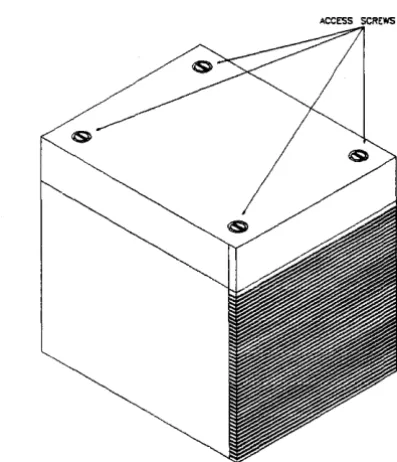
[image:36.514.130.395.162.503.2]Safety
Considerations
Warning
Warning
G
The HP 64000-UX Microprocessor Development Environment along with the HP 64410SC/SD Emulation System isa Class 1 in-strument (provided with a protective earth terminal) and meets safety standard IEC 348, "Safety Requirements for Electronic Measuring Apparatus". This Class I instrument also meets Hewlett-Packard Safety Class I requirements and has been shipped in a safe condition.
The user should review both the instrument and manual for safety markings and instructions before operation. Read and be-come familiar with the "Safety Summary", printed following the Certification/Warranty page of this manual, and the additional items listed below.
SHOCK HAZARD! DO NOT ATTEMPT TO DISRUPT PROTECTIVE GROUND! Any interruption of the power cord protective con-ductor (third prong of power cord plug) inside or outside the HP 64120A Instrumentation Cardcage or disconnection of the protective earth terminal in the power source (wall outlet) is likely 10 make the HP 64000-UX Microprocessor Development Environment DANGEROUS! Intentional interruption of the power cord protective conductor is prohibited.
SHOCK HAZARD! ONLY QUALIFIED PERSONNEL SHOULD SER· VICE. Any adjustment, maintenance, or repair of the opened in-strument must ONLY be carried out by QUALIFIED PERSONNEL aware of the HAZARDS involved.
Warning
Preinstallation
Inspection
SHOCK HAZARD! DO NOT USE IF SAFETY FEATURES HAVE BEEN IMPAIRED. If the safety features of the instrument have been damaged or defeated, the instrument shall not be used until repairs are made which restore the safety features. The safety features of the instrument could be disabled in the fol-lowing instances:
1. The instrument shows visible damage.
2. The instrument fails to perform correct measurements.
3. The instrument has been shipped or stored under
un-favorable environmental conditions. Refer to the Service Supple-ment portion of this manual for information on the environmen-tal specifications of storage and shipment.
Unpack all of the emulation system circuit boards, cables, pod, and related equipment. Carefully inspect the equipment for damage that may have occurred during shipping. If any damage is found, please contact your nearest Hewlett-Packard Sales/Ser-vice Office as soon as possible.
Installing Your
Emulation System
Hardware
Warning
Installation
Instructions
Warning
Caution
I
This section tells you how to install your emulation hardware into the HP 64120A Instrumentation Cardcage.
SHOCK HAZARD! INSTALLATION SHOULD ONLY BE PER· FORMED BY QUALIFIED PERSONNEL. Any installation, servicing, adjustment, maintenance, or repair of this product must be per-formed only by qualified personnel. Make sure power is off
prior to performing any of the installation instructions given below.
Proceed as follows to install the Emulation System and related equipment:
SHOCK HAZARD! HAVE YOU READ THE SAFETY SUMMARY? Read the safety summary at the front of this manual before in-stallation or removal of the Emulation Subsystem.
DAMAGE TO CARDS AND CAGE! Power to the HP 64120A In-strumentation Cardcage must be removed before installation or removal of option cards (emulation, etc.) to avoid damage to the option cards and the development environment.
Turn Off Power
Turn OFF power to the HP 64120A Instrumentation Cardcage (see figure 2-1 for the location of the power switch on the HP 64120A Instrumentation Cardcage).
Remove The Card Cage Cover
[image:40.507.147.346.241.472.2]Connect The Emulator Pod Cables To The Emulator Boards
There are six cables from the emulation pod that must be con-nected to various cards in the card cage. Connect these cables as follows:
1 . Connect the two 44-conductor cables from the pod to the Emulator Control Board (HP Part Number 64410-66506). There are no color dots to follow because it does not matter which of the 44-conductor cables are connected to each of the 44-pin connectors.
2. Connect the 50-conductor cable from the pod to the Emulator Control Board (HP Part Number 64410-66506).
3. Connect the three 64-conductor cables from the pod to the Analysis Bus Generator board (HP Part Number 64411-66502) following the yellow, red, and brown color dots for proper connections.
The pod cables connected to the ABG board ( 6441 lA) are
protected by a plastic cover. After connecting the three 64 JX>Sition cables to the ABG board, secure the plastic cable cover to the ABG board by connecting four screws as shown in figure 2-3. Use a Tone® TX 6 screwdriver.
Figure 2-3. ABG Protective Plastic Cable Cover
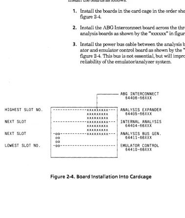
Install Boards Into The Card Cage
HIGHEST SLOT NO.
NEXT SLOT
NEXT SLOT
LOWEST SLOT NO.
Four adjacent card cage slots are required for the circuit boards. Install the boards as follows:
1. Install the boards in the card cage in the order shown in figure 2-4.
2. Install the ABG Interconnect board across the three analysis boards as shown by the "xxxxxx" in figure 2-4.
3. Install the power bus cable between the analysis bus gener-ator and emulgener-ator control board as shown by the "oo" in figure 2-4. This bus is not essential, but will improve reliability of the emulator/analyzer system .
. - - - ABG INTERCONNECT
64406-66XXX
---xxxxxxxxx--- ANALYSIS EXPANDER xxxxxxxxx 64405-66XXX
xxxxxxxxx
---xxxxxxxxx--- INTERNAL ANALYSIS xxxxxxxxx . 64404-66XXX
xxxxxxxxx
-00---xxxxxxxxx--- ANALYSIS BUS GEN.
oo 64411-66XXX
00
-00--- EMULATOR CONTROL
64410-66XXX
Figure 2-4. Board Installation Into Cardcage
[image:43.515.59.437.81.527.2]Installing The
Emulation Probe
Into The Target
System
Caution
•
Secure The Pod Cables
Each pod cable has a metal ferrule for strain relief. Snap the fer-rule into one of the cable clamps on the instrumentation card cage.
If your instrumentation card cage does not have cable clamps, you can order them from Hewlett-Packard Co.
Reinstall Card Cage Access Cover
Reinstall the card cage access cover and secure in place with the hold-down screws.
PROTECT AGAINST STATIC DISCHARGE! The emulation
Caution
Caution
•
&
•
POSSIBLE DAMAGE TO EMULATION POD! Do not install the emulation probe into the processor socket with power ap-plied to the target system. The pod may be damaged if power is not removed before installation.
When installing the emulation probe, be sure the probe is in-serted into the processor socket so that pin 1 of the emula-tion probe aligns with pin 1 end of the processor socket. Damage to the emulation equipment may result if the probe is incorrectly installed .
PROTECT YOUR CMOS TARGET SYSTEM COMPONENTS! If your system includes any CMOS components--turn on the tar-get system first, then turn on the HP 64120A Instrumentation Cardcage; likewise, turn off the development environment first, then the target system.
The emulation probe is provided with a pin protector that
prevents damage to the probe when not in use (see figure 2-4). DO NOT use the probe without a pin protector installed. If the emula-tion probe is being installed on a densely loaded circuit board, there may not be enough room to accommodate the plastic shoulders of the probe. If this occurs, another pin protector may be stacked onto the existing pin protector.
To install the microprocessor connector in a target system with a Pin Grid Array (PGA) socket (see figure 2-5), proceed as follows:
1. Remove the 68020 processor from the target system proces-sor PGA socket.
2. Store the 68020 processor in a protected environment. Note the location of pin 1 on both the microprocessor con-nector and the target system socket.
PIN A1
[image:46.510.98.402.77.348.2]3. Install the probe cable connector into the target system processor socket.
Figure 2-5. Installing Emulator Probe Into PGA Socket
Caution
Install Software
Installing 68020
Emulation
Software Updates
Turning On The
HP 64120A
Caution
•
Refer to the Installation Notice that you received with your HP 64000-UX media for complete software installation instructions.
After installing a new copy of the 68020 Emulation Software on a system, cycle the power off and then back on for all HP 64120 cardcages containing 68020 emulators. This updates and initial-izes all emulation software data structures.
When installing a different revision of the 68020 emulator software, remake all existing configuration files. Configuration file names are suffixed by" .EA" and" .EB". The simplest method is to delete the ".EB" file before loading the configuration file.
The power switch for the HP 64120A Instrumentation Cardcage is identified in figure 2-1.
PROTECT YOUR CMOS TARGET SYSTEM COMPONENTS! If your system includes any CMOS components--turn on the tar-get system first, then turn on the HP 64120A Instrumentation Cardcage; likewise, turn off the instrumentation cardcage first, then the target system. ·
Turn the HP 64120A Instrumentation Cardcage power on.
Getting Started
Overview
Introduction
This chapter describes how to do the following tasks:
• Create a subdirectory in which you can store your 68020 re-lated files.
• Initialize and define a measurement system.
• Assemble, compile, and link the emulation monitor and demonstration programs.
3
• Access the emulation system from the monitor level softkeys.
• Modify the default emulation configuration and map memory.
• Run an emulation session.
This chapter gives an operational overview of the emulation process. The chapter leads you ste}>-by-step through the tasks you must do to prepare your system for emulation and leads you through an emulation session. Emulation features are not ex-plained in depth in this chapter. Its purpose is to familiarize you with the emulation process. Read the entire chapter and go through all exercises in the order presented. This will give you an understanding of the basic operation of the emulator.
Emulation System
Used For Examples
Making A
Subdirectory For
Your
68020
Project
The examples given in this chapter (and throughout this manual) were developed with an emulation system including the com-ponents listed below.
• HP 64410SD Emulation System
• HP 648708 Cross Assembler/Linker for MC68020
• HP 649038 68020 C Cross Compiler
Before you start a new project, make a subdirectory for the project. This enables you to keep your files for each project separate from other files. Follow the rules listed below when you make your subdirectory.
• Give the subdirectory a name consisting of from one to four-teen characters. If more than fourteen characters are used, all characters after the fourteenth character are truncated.
• Any characters may be used in the name. A void conflict with special characters used in the HP-UX system software by restricting your subdirectory names to alphanumeric charac-ters and the underscore ( _ ) character.
Note The path /usr/hp64000/bin must be added to the PATH parameter in your ".profile" file in order to execute HP 64000-UX commands as given in the examples in this manual. Other-wise, you must type the entire path name for HP 64000-UX com-mands, e.g., /usr/hp64000/bin/pmon instead of pmon.
Do the following steps to make a subdirectory for your 68020 project:
1 . Log in to the system using your login and password.
2. Enter pmon Return. This accesses the HP 64000-UX sys-tem monitor. The HP 64000-UX syssys-tem monitor is softkey driven. You should see softkey labels displayed on your screen.
3. Press the ---ETC---softkey repetitively until the makedir softkey appears as an option on the softkey label line.
4. Press the makedir softkey and type in the name you wish to use for your directory (the name em68020 is used throughout this manual). Press the Return key on the keyboard.
makedir em68020 Return
You now have a subdirectory named em68020.
Whenever you log in to your system to work on the 68020 project, you should change to this directory (using the chng dir softkey).
If you do most of your work on the 68020 project, youC"an modify your". profile" file to change to this directory whenever you log in.
If the permissions are set so that you can alter your own" .profile" file, add the line "cd $HOME/em68020" to your ".profile" file. You will then be in the new subdirectory each time that you log in. If
the permissions are set so that you cannot modify your ".profile"
Initializing And
Configuring Your
Measurement
System
Note
file, see your HP-UX system administrator. The examples in this manual use the chng_ dir command to change directories.
If you have already initialized the instrumentation cardcage and defined your measurement system, skip this section and go to the next section titled "Preparing Your Program Modules".
Refer the Measurement System manual for the HP 64000-UX
Microprocessor Development Environment for detailed informa-tion on initializing and configuring measurement systems. The following procedure gives you a brief overview of the initializa-tion and configurainitializa-tion process.
Note
1. Press MEAS SYS.
The MEAS SYS softkey is displayed after you enter the HP 64000-UX system monitor by executing the pmon command.
You are now in the measurement_system application. The softkeys displayed at this level enable you to initialize and configure your measurement system.
2. Press msinit Return.
If you have only one system in your instrumentation cardcage, the softkey label line will disappear and the mes-sage ''Working" will appear on the STATUS line. After a few seconds, the message "Hit return to continue" will ap-pear under the STATUS line. Press Return. The message will disappear and the softkey labels will return.
If you have more than one system in your instrumentation cardcage, the softkey label line will disappear and the mes-sage ''Working" will appear on the STATUS line. After a short time, a list of boards in the card cage may be dis-played on the screen. Messages may appear on screen as-king you to identify the boards in the different systems. After you have identified any boards requested by the sys-tem, the message "Hit return to continue" will appear under the STATUS line. Press Return. The message will disappear and the softkey labels will return.
3. Press msconfig Return.
The screen now displays the module(s) available to be as-signed (top of the screen) to a measurement system (middle of the screen).
4. Enter make_ sys emul682k Return.
5. Press add. If your 68020 emulator is the only system in the instrumentation cardcage, it will be assigned as module 0 as shown at the top of the display. If more than one system is installed in the instrumentation cardcage, the 68020 system module number may be different from 0. Identify the module number of the 68020 emulator shown at the top of the display and type it in from the keyboard. Press name it, type in em68020 from the keyboard, and press Returll.
add 0 naming_ it em68020 Return.
6. Press end Return.
This command causes the system to exit the measurement configuration mode and return to the measurement system level.
7. Press -GO BACK-to exit the measurement system level and return to the HP 64000-UX system monitor.
Preparing Your
Program Modules
Program modules must be assembled or compiled, linked, and then mapped to emulation or target memory before the absolute code can be loaded into the emulator. The memory mapping proce-dure is described briefly in this chapter and is described in detail in chapter 4. The assembly and compile procedures are not described in this manual. Refer to your
as-sembler/linker/librarian and compiler manuals for detailed in-structions on these processes.
The following procedures require the HP 64870S
As-sembler/Linker/Librarian for 68000/10/20 and the HP 64903S 68020 C Cross Compiler. If you have these products on your sys-tem, go to the the section titled "Copying the Demonstration Programs to Your Subdirectory".
If you do not have these products on your system, you can still per-form the demonstration emulation procedures in this manual. A complete set of files required to perform the emulation examples in this manual are provided on the media with your emulation software. The file set is located in directory
/usr/hp64000/demo/emul32/hp64410.
You must change to the directory containing the demonstration files in order to run the emulation examples. To change direc-tories, press the chng clir softkey and enter the directory path-name /usr/hp64000/demo/emul32/hp64410. The command line should appear as follows:
cd /usr/hp64000/demo/emul32/hp64410
Press the Return key. You should now be in the 68020 demo sub-directory. You can verify this by executing the HP-UX pwd (present working directory) command.
Go to the section titled "Preparing The Emulation System".
Note
Copying The Demonstration Programs To Your Subdirectory
The README file in the demo directory contains more informa-tion on the demonstrainforma-tion files. To read the README file, enter the command:
!more /usr/hp64000/demo/emul32/hp6441 O/README
The demonstration programs used in this manual are provided on the media shipped with your 68020 emulation system in directory /usr/hp64000/demo/emul32/hp64410. The programs are:
simint.c
towers.c
Simulated interrupt routines for the demonstration program.
The demonstration program. This program solves the popular "Towers of Hanoi" brain teaser puzzle. The program demonstrates many features of the emulator, including simulated I/O and simulated interrupts.
Listings of the demonstration programs are included in appendix C of this manual.
Enter the following commands to copy the programs to your sub-directory.
Compiling and
Linking the Program
Modules
The following sections give examples of how to compile user programs, and link the user programs and emulation monitor into a single executable file. Refer to your compiler manuals for detailed information on these processes.
Compiling The Demonstration Programs.
Enter the following command to compile the demonstration program towers.c:
!cc68020 -hLc towers.c Return.
When the message "Hit return to continue" is displayed, Press Return and enter the following command to compile the simu-lated interrupt routine simint.c:
!cc68020 -hLc simint.c Return.
When the message "Hit return to continue" is displayed, press Return. Your demonstration program files are now compiled.
The-L assembler option causes a listing file to be generated.
The-h option causes an HP 64000 format assembler symbol file
(.A extension) to be generated for debugging purposes. This file is used by the emulator for symbolic debugging.
The -c option suppresses automatic linking of the programs (ob-ject files are generated).
Enter the following command:
list dir Return.
Note that four filetype extensions are listed for each compiled file:
c: source file
o: relocatable object file A: assembler symbols file
0: compiler listing file.
Linking Modules
After you have compiled your source programs, they must be linked, together with the emulation monitor and any required library routines, into an executable module. 68020 emulation en-vironment dependent routines and library routines needed for the
demonstration program are provided with the HP 649038 68020 Ccompiler.
The environment dependent routines provide for program setup, dynamic memory allocation, and program input and output in the 68020 emulation environment. These routines are found in direc-tory /usr/hp64000/env/hp64410. See the HP 649038 68020 C Compiler manuals for detailed information on environment de-pendent routines.
The linker can be used interactively or with a command file to link your programs.
A linker command file that will work with the demonstration program is provided with the HP 64410 demonstration software. The file is named towers.k. Copy the file into your subdirectory using the command:
copy /usr/hp64000/demo/emul32/hp64410/towers.k towers.k Return
You can view the command file on your screen by entering the command:
!more towers.k Return
The program shown in figure 3-1 should be listed on your screen.
************************************************************************
* LSD:@(#) ... .
* @( mkt id) ... .
*
*
This is a modified version default linker command file for the*
HP 64903 Advanced 68020 C Cross Compiler to be used with the HP 64410*
68020 Emulator/Analyzer demonstration software. It should be used*
along the emulator configuration file config.EA.*
* NOTE: Revisions 2.00 of the HP64903 Compiler and 1.20 of the HP64870
* Assembler/Linker or later are required.
************************************************************************
CHIP 68020
SECT env=$400
*
Load address for program/canst sections ORDER env,prog,simint,const, lib,libc,libmSECT mon=$20000
*
Load address for emulation monitor sections ORDER mon,mondataSECT stack=$7FFF8000 * Load address for stack section SECT envdata=$FFFEAOOO
*
Load address for data sections ORDER envdata,data, libdata,libcdata,libmdata,heap************************************************************************
*
Set register A5 to the beginning address of the data section + 32k*
so that the AS-relative address mode may be used. If this directive* is omitted ?A5 has an undefined value.
************************************************************************
INDEX ?A5,data,$8000
[image:59.509.66.419.69.367.2]LOAD /usr/hp64000/env/hp64410/crt0.o LOAD /usr/hp64000/lib/68020/libc.a LOAD /usr/hp64000/lib/68020/lib.a LOAD /usr/hp64000/env/hp64410/monitor.o LOAD /usr/hp64000/env/hp64410/env.a END
Figure 3-1. Towers.k Linker Command File
Enter the following command to link your program modules:
!ld68k -Lh-c towers.k-o towers.X simint.o towers.o
>
towers.MAP Return
After a few seconds, the message "Hit return to continue" will ap-pear under the STATUS line. Press Return. The message will disappear and the softkey labels will return.
You will use the information contained in the linker listing file towers.MAP when you map emulation memory in the next sec-tion.
Preparing The
Emulation System
Accessing The Emulation System
Modifying The
Preparing the emulation system consists of the following steps:
1. Plugging the emulator probe into your target system (for in-circuit emulation).
2. Accessing the emulator through the MEAS_SYS applica-tion.
3. Modifying the default emulation configuration to match your system requirements.
4. Loading your user program into emulation or target sys-tem memory.
The following procedures use the emulator in out-of-circuit mode (no target system). Target system plug-in issues are discussed in detail in chapter 5 of this manual.
Access your emulation system as follows:
1. Press MEAS_ SYS.
2. Press emul682k em68020 Return.
You are now in the emulation system application. The emulation softkeys are displayed at the bottom of your screen.
emula-Modify the answers to the emulation configuration questions as shown below in order to have the demonstration program run properly. To modify to the emulation configuration questions, enter the command:
modify configuration Return
The first emulation configuration question should be displayed. If not, return to the previous section titled" Accessing the Emula-tion System" and repeat the steps described there.
Answer the emulation configuration questions as follows.
Emulation Configuration Question
Restrict to real-time runs? no
(Enable the emulation system to break to the emulation monitor)
Disable breaks into monitor? no
(Enable all emulation functions)
Reset into the monitor? yes
(A reset command, followed by a run command, will cause theJJrocessor to begin executing the emulation monitor)
Enable emulator use of software breakpoints? yes
(Enable emulator software breakpoints)
Software BKPT instruction number (0 .. 7)? 7
(Set the emulation software breakpoint number to 7)
Enable internal 68881 FPU? no
(Enable emulator use of the internal 68881 FPU in the emulation pod)
FPU coprocessor ID ( 1 .. 7)? 1
(Use the default coprocessor ID of 1)
Your Answer
Return
Return
Return
Return
Return
yes Return
Return
Name of custom register format file? /usr/hp64000/inst/emul32/0400/0001/custom spec
(Use the default coprocessor format specification file) Return
Modify memory configuration? no
(Modify the emulation memory map)
Break processor on write to ROM? yes
yes Return
Return
(Break to the emulation monitor if the processor attempts to write to memory mapped as emulation or target ROM)
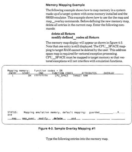
Enter the following memory map commands.
delete all Return
(Delete all user defined entries)
Modify default guarded Return
Emulation Configuration Question (Continued) Your Answer
map 020000h thru 022fffh emulation ram width32 Return
(Map memory locations for the emulation monitor)
map 07fff8000h thru 07fffffffh emulation ram width32 Return
(Map memory locations for the program stack)
map OfffeaOOOh thru Offffffffh emulation ram width32 Return
(Map memory locations for the data sections of the demonstration module)
Modify emulator pod configuration? no
(Use the default emulation pod configuration)
end Return
(End memory configuration)
Return
Modify simulated 1/0 configuration? no yes Return
(Modify the simulated 110 configuration)
Enable polling for simulated 1/0? no yes Return
(Enable the emulation software to read the simulated 110 control address to
determine if the demonstration program has requested any simulated 110 commands)
Function code data space? none Return
(Use the default value)
Sirnio control address 1? SIMIO CA ONE systemio buf Return
(Specify the control address defined in the demonstration program)
Sirnio control address 2 .. 6? SIMIO CA XXX Return
(Select the default value for the remaining simio control address questions)
File used for standard input? /dev/simio/keyboard Return
(Select the host keyboard for simulated 110 input)
File used for standard output? /dev/simio/display Return
(Select the host display for simulated 110 output)
File used for standard error? /dev/simio/display Return
(Select the host display as the simulated 110 error output)
Modify simulated interrupt configuration? no yes Return
(Modify the default simulated interrupt configuration)
Enable polling for simulated interrupts? no yes Return
(Enable the emulation software to read the simulated interrupt control address to determine if the demonstration program has requested any simulated interrupt com-mands)
Emulation Configuration Question (Continued) Your Answer
Function code data space? none Return
(Select the default value)
Simulated interrupt control address? SIMINT CA sim int ca Return
(Specify the control address defined in the demonstration program)
Maximum delay (in milliseconds) for simulated interrupt? 25 3000Return
(Specify 3000 milliseconds)
Configuration file name? democonfig Return
(Name the configuration file democonfig)
Note
When the emulator is finished loading the memory mapper, the STATUS line will indicate that the emulation processor is Reset. The emulator is ready to be used.
You now have two configuration files named democonfig in your directory. The .EB file extension is a binary file used by the emulator. The .EA file extension is an ASCII file that you can edit using an editor residing on your host system. The emulation configuration file provides you with an easy method to recon-figure your emulator upon entry to the emulation application. Upon reentry to the emulator, enter the command:
load configuration democonfig Return
Using The
Emulator
Note
This section demonstrates the use of some of the basic emulator commands. Work through the examples in the sequence given in this section. Otherwise, the displays you get on your workstation screen may not be the same as those shown in the manual. After you have worked through the examples in this section, you may then execute other commands to gain a better understanding of the emulator's operation. See the 68020 Analysis Specifics manual and theReferenceManualfor 16-and32-Bitlnternal Analysis for detailed information on using the emulator's analysis
features.
The displays you obtain on your system for the examples in the following sections of this chapter may vary from those shown in this manual, depending on the type of terminal or workstation you are using.
Displaying Global
Symbols
The display global symbols command displays global (exter-nally defined) symbols in the program modules you have loaded into emulation or target memory. To display global symbols, enter the following command:
display global_ symbols Return.
You should see a display similar to the following display on your screen
Global symbols in
Procedure symbols towers
Procedure name Address range Return Segment _startup ~--o~o~o~o'"""o5AO- 00000111 ----00000110 - COMM clear screen 00000970- 000009AB 000009AA PROG close- 00000828- 00000863 00000862 PROG disable int 00001822- 00001838 00001834 PROG enable Tnt 00001804- 00001821 0000181A PROG exec cmd 000009F6- OOOOOAB5 OOOOOAB4 PROG initsimio 000007AO- 000007CD 000007CC PROG kill OOOOOAB6- OOOOOAF9 OOOOOAF8 PROG lseek OOOOOB4A- OOOOOBF1 OOOOOBFO PROG main 000010A8- 00001189 00001182 PROG open 000007CE- 00000827 00000826 PROG pos_cursor 000009AC- 000009F5 000009F4 PROG read 00000864- 000008F3 000008F2 PROG unlink OOOOOAFA- 00000849 00000848 PROG wait_for_io 00000788- 0000079F 0000079E PROG
Off set ---..-00000000 000001E8 OOOOOOAO 0000001E 00000000 0000026E 00000018 0000032E 000003C2 00000000 00000046 00000224 OOOOOODC 00000372 00000000 STATUS: M 6 8 0 2 0 - - R e s e t . . . - - - · .. R ....
display global_symbols
Displaying Local
Symbols
You can view local symbols within a file or module using the dis-play local symbols in command. To view local commands in
the demonstration program, enter the following command:
display local_ symbols_ in towers.c: Return.
Symbols in towers.c: Procedure symbols
Procedure name Address range ask for number
---o.,...,o ....
o"""o...,..118A- 00001389 init_display 00001688- 00001761 main 000010A8- 00001189 move_disc 00001604- 00001687 pause 000013BA- 0000140F place_disc 0000159A- 00001603 remove disc 00001538- 00001599 show dTscs 00001410- 00001537 towers 00001762- 00001801 Static symbolsReturn Segment Offset ----00001382 - PROG ---..,..OOOOOOE2 0000175A PROG 000005EO 00001182 PROG 00000000 00001680 PROG 0000055C 00001408 PROG 00000312 000015FC PROG 000004F2 00001592 PROG 00000490 00001530 PROG 00000368 000017FA PROG 000006BA
Symbol name - - - Address range - - - Segment _ _ ___,,, Offset
0String1 000018E4 COMM 00000084
0String10 00001A3E COMM 000001DE 0String11 00001A40 COMM 000001ED STATUS: M68020--Reset _ _ _ _ _ _ _ _ _ _ _ _ _ _ _ _ _ _ _ _ _ ... R ....
display local_symbols_in towers.c:
Note that the ".c" file extension is used to specify C language files and the ".s" file extension is used to specify assembly language files.
Displaying Memory
Memory :mnemonic address data
10A8 4E560000 10AC 2F08 10AE 2FOA 1080 247CFFFE+ 1086 267COOOO+ 108C 4289FFFE+ 10C2 60FFOOOO+ 10C8 4E71 10CA 7001 10CC 2040 10CE 4850 1000 4EB90000+ 1006 588F 1008 4289FFFE+ !ODE 7000 10EO 2040
The display memory command enables you to view the contents of either emulation or target memory locations. Enter the command:
LINK. W MOVE.L MOVE.L MOVEA.L MOVEA.L CLR.L BRA.L NOP MOVEQ MOVEA.L PEA JSR ADDQ.L CLR.L MOVEQ MOVEA.L
display memory main mnemonic Return
A6,#$0000 A3,-{A7) A2,-(A7) #$FFFEA1B4,A2 #$000013BA,A3 $FFFEA180 $00001158 #$00000001,DO DO,AO {AO) $00000970 #4,A7 $FFFEA188 #$00000000,DO DO,AO
STATUS: M68020--Reset _ _ _ ,__ _ _ _ _ _ _ _ _ _ _ _ _ _ _ _ _ ... R .... display memory main mnemonic
Modifying Memory
You can modify emulation memory locations mapped as either RAM or ROM. The speed of the towers demonstration program is controlled by the variable loc delay. We will set the value of loc delay to 0 so that the program runs at maximum speed. In order to watch the memory display change as the variable is modified, we will display an area in memory repetitively and then modify the memory. Enter the following command:Memory :long address 1860-6F 1870-7F 1880-8F 1890-9F 18AO-AF 18BO-BF 18CO-CF 1800-DF 18EO-EF 18FO-FF 1900-0F 1910-lF 1920-2F 1930-3F 1940-4F 1950-5F
display memory loc_delay long repetitively Return
You should see a display similar to the following on your worksta-tion screen.
words :blocked :repetitively data : hex
000001F4 20202020 2020207C 7C202020 20202020 20202020 2020317C 7C312020 20202020 20202020 2032327C 7C323220 20202020 20202020 3333337C 7C333333 20202020 20202034 3434347C 7C343434 34202020 20203535 3535357C 7C353535 35352020 20363636 3636367C 7C363636 36363620 37373737 3737377C 7C373737 37373737 09095075 7A7A6C65 20776974 68202564 20646973 63732063 616E2062 6520736F 6C766564 20696E20 25642060 6F766573 2E202020 20200AOO OAOA4578 65637574 65202760 6F646966 79206865 79626F61 72645F74 6F5F7369 60696F27 20746865 6E20656E 74657220 6F6E6520 6F662074 68652066 6F6C6C6F 77696E67
:ascii
4
4 55 55 666 666 7777 7777 .. Pu
h %d dis e solved aves. ecute 'm yboard_t then en of the f
d
1122
333 333 444 i444 555 555 666 I 66777 1777
zzle wit cs can b in %d m
.•.• Ex
odify ke o simio'
ter one allowing
STATUS: dis p 1 ay M68020--Reset memory 1 oc_ d-e 1..-a-y-... l o-n-g--re_p_e__,.t__,.i..,....t ..,....i v-e ... l_y _ _ _ _ _ _ _ _ _ _ _ ... R ....
Memory :long address 1860-6F 1870-7F 1880-8F 1890-9F 18AO-AF 1880-8F 18CO-CF 1800-0F 18EO-EF 18FO-FF 1900-0F 1910-lF 1920-2F 1930-3F 1940-4F 1950-5F
Enter the command:
modify memory long loc_ delay to 0 Return
Note that the first long word in the display (memory location loc _delay) now shows a longword value ofOOOOOOOOh.
words :blocked :repetitively data :hex
00000000 20202020 2020207C 7C202020 20202020 20202020 2020317C 7C312020 20202020 20202020 2032327C 7C323220 20202020 20202020 3333337C 7C333333 20202020 20202034 3434347C 7C343434 34202020 20203535 3535357C 7C353535 35352020 20363636 3636367C 7C363636 36363620 37373737 3737377C 7C373737 37373737 09095075 7A7A6C65 20776974 68202564 20646973 63732063 616E2062 6520736F 6C766564 20696E20 25642060 6F766573 2E202020 20200AOO OAOA4578 65637574 65202760 6F646966 79206865 79626F61 72645F74 6F5F7369 60696F27 20746865 6E20656E 74657220 6F6E6520 6F662074 68652066 6F6C6C6F 77696E67
:ascii
4
4 55 55 666 666 7777 7777 .. Pu
h %d dis e solved oves. ecute 'm yboard_t then en of the f
1II1 22 22 333 333 444 444 555 555 666 1666 777 777 zzle wit cs can b in %d m
.... Ex odify ke o simio' ter one allowing
STATUS: M68020--Reset ... R ....
modify memory 1 on g ":'"'l o_c ___
d:-e-=-l-ay-...,.t-o-0,.---Running from the Transfer Address
Now that you have used some of the display and modify features of the emulator, it is time to
M.F1
the demonstration program and use some of the run time features of the emulation system. Enter the following command:run from transfer address Return
Displaying Registers
M68020 Registers
The display registers command enables you to look at the con-tents of the 68020's CPU registers and the concon-tents of the 68881 floating point coprocessor registers. Enter the following command:
display registers cpu Return
The contents of the following 68020 CPU registers are displayed on the screen:
program counter (PC)
source function code register (SFC) destination function code register (DFC) data registers (DO--D7)
address registers (AO-A 7) user stack pointer (USP) vector base register (VBR) cache address register (CAAR) master stack pointer (MSP) interrupt stack pointer (ISP) status register (STATUS) cache control register (CACR)
NextPC 00000792 SFC 0 MOT RSVO OFC 0 MOT RSVD
D0-07 00000000 00000092 000003FC 00003248 OOOOOOFF 00000000 00000064 00000000 AO-A6 OOOOOOFF FFFEA037 FFFEA698 FFFEA78C FFFEA034 FFFF21A8 7FFFFF02
USP 00020060 VBR 00000000 CAAR 00000000
MSP 00020060 <tl to s m i x n z v c> <f e> *ISP 7FFFFF02 STATUS 2704 0 0 1 0 7 0 0 1 0 0 CACR 0 0 0
STATUS: M68020--Runni ng _ _ _ _ _ _ _ _ _ _ _ _ _ _ _ _ _ _ _ ... R .... display registers cpu
M68020 Registers
Press the break softkey, then press Return.
The registers display is updated and the status line now reads "STATUS: M68020--Runninginmonitor". If a display registers command has been executed in the current emulation session, the registers display is updated whenever a break to the emulation monitor program occurs.
NextPC 00000792 SFC 0 MOT RSVD DFC 0 MOT RSVD
00-07 00000000 00000092 000003FC 00003248 OOOOOOFF 00000000 00000064 00000000 AO-A6 OOOOOOFF FFFEA037 FFFEA698 FFFEA78C FFFEA034 FFFF21A8 7FFFFF02
USP 00020060 VBR 00000000 CAAR 00000000
MSP 00020060 <tl tO s m i x n z v c> <f e> *ISP 7FFFFF02 STATUS 2704 0 0 1 0 7 0 0 1 0 0 CACR 0 0 0 NextPC 00000790 SFC 0 MOT RSVD DFC 0 MOT RSVD
D0-07 00000092 00000092 000003FC 00003248 OOOOOOFF 00000000 00000064 00000000 AO-A6 OOOOOOFF FFFEA037 FFFEA698 FFFEA78C FFFEA034 FFFF21A8 7FFFFF02
USP 00020060 VBR 00000000 CAAR 00000000