Technology (IJRASET)
©IJRASET 2013: All Rights are Reserved
160
Loss Reduction Using the Smart Power Flow
Controller by Tap-Changing Algorithm of Sen
Transformer
Junia.D1, Dr.K.Elango2
1
PG Scholar,2 Professor & HOD, Department of Electrical and Electronics Engineering, Valliammai Engineering College Chennai
Abstract - The transmission systems is to handle the power efficiently from generation stations to load stations. Even though a considerable amount of power is lost in transmission network components. As a result, a appropriate power flow control devices used to increase the transmission efficiency is implemented. However, the inserted power flow control devices itself consume power which may increase the power loss further. In this paper, Sen Transformer (ST) is recommended for power loss reduction which is capable of regulating the active and the reactive power flow by selecting the best combination of tap-settings of the ST. The tap-changing algorithm of the ST has been implemented through a FORTRAN code. Thus the Phase Angle Regulator (PAR) and Sen Transformer (ST) are connected to a five bus test system using MATLAB/SIMULINK. The results obtained from the simulation results of the ST are compared with the results of the UPFC. The comparison shows better results and hence the performance of the ST is preferred.
Keywords - Power flow control, Loss reduction, Flexible ac transmission systems (FACTS), Unified power-flow controller (UPFC), Sen Transformer (ST).
I. INTRODUCTION
Power systems are principally divided to generation, transmission and distribution subsystems. The generation stations are always located closer to the resources. The main goal of the transmission subsystem is to transfer the generated power to load centers at highest possible efficiency. However, many factors increase transmission lines power loss.
Each of the power flow control parameters such as voltage, angle and reactance can be changed with the use of the existing solutions are shunt inductor/capacitor for voltage regulation, Phase-shifting transformer for phase angle regulation and Series inductor/capacitor for series reactance regulation.
By changing any one of the parameters using a power flow controller, both the active and the reactive power flow in a transmission line can be affected.
As a result, Installation of new transmission lines, or extension of current carrying capacity of the available ones are some of the solutions for efficient power flow but due to the right of way, high costs, the environmental constraints, and public policies, these solutions are not preferable [1]
Inserting power flow control such as FACTS devices in power networks has many advantages as they can enhance system security, increase power transfer capability, and reduce power loss. Generally FACTS controllers are very effective and provide the most flexible solutions. Among them, the Unified Power Flow Controller (UPFC) is the most flexible. It has the ability of voltage and power flow control [4],[5], but it is limited due to its relatively high installation and operating costs . The UPFC, which is based on power electronic Voltage Sourced Converter, has the capability of providing a fast dynamic response. Nevertheless, this capability is not necessary in most utility's applications, where the need is to regulate the line voltage and power flow in a relatively slow mode. The UPFC offers fast response (in ms), but this capability cannot be utilized [10].
Technology (IJRASET)
©IJRASET 2013: All Rights are Reserved
161
To address this issue, the Sen Transformer (ST) was introduced [6]. The ST uses time-tested components, such as transformers and tap changers, and injects a variable voltage of magnitude and phase angle, such as a UPFC connected in series with the transmission line to regulating the active and reactive power flow independently in the line. Although the power circuit of the UPFC is capable of sub cycle response, the adjustable responses of currently installed UPFCs are set in the range of tens of line cycles and slower, thereby not utilizing the full speed response capability of the power electronic converter. In most power systems applications, the response of mechanical tap-changers in the range of seconds is quite acceptable
Fig. 1(a) shows a transmission line on which the active and reactive power flows, and are governed by the following equations:
( )
( ) .
II. BACKGROUND
The effect of a series-connected compensating voltage of the power flow in a transmission line.A direct method of voltage regulation by tap changing. To regulate the voltage at any point in a transmission line, an in-phase or an out-of-phase voltage is connected in series with the line.
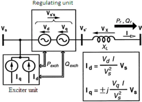
Fig. 2. (a)Voltage regulator circuit, (b) phasor diagram, and (c) controller
The voltage regulator scheme for regulating the voltage at any point in a transmission line is shown in Fig. 2(a).The exciter unit consists of a three-phase connected primary winding, which is impressed with the line voltage Vs. The voltage-regulating unit is the combination of six secondary windings where two windings in each phase for a bipolar voltage junction. The line is regulated by adding a compensating voltage, either in or out of phase with the line voltage Vs. Fig. 2(b) shows the corresponding phasor diagram. The bipolar compensating voltage in any phase is induced by a autotransformer action with two windings placed on the same phase of the transformer core. The controller is fed with two input signals where one is the exciting line voltage vs, and the other is the reference voltage Vs*as shown in fig.2(c). The tap control unit in the controller, monitors the magnitude of the exciting voltage, Vs, and the reference voltage, Vs*, and switch on the appropriate tap, in the voltage-regulating unit, in order to regulate the line voltage at Vs*.
[image:3.612.179.432.286.501.2]Technology (IJRASET)
©IJRASET 2013: All Rights are Reserved
162
Fig.3.Thyristor-controlled tap changer
The other side of each thyristor switch is connected together at point A. Depending on which thyristor is on, the voltage between the junction A and B can be varied between zero and the full winding voltage with desired steps in between. In the mechanical arrangement, a load tap changer connects with one of various taps to give variable number of taps between the connected tap and one end of the winding.
III. SEN TRANSFORMER
In a Sen Transformer (ST), as shown in Fig.4 (a), there are two units: exciter unit and compensating-voltage unit. The exciter unit consists of three primary windings (A, B, andC) that are Y-connected and placed on each limb of a three-limb, single core transformer. The three-phase transmission line voltage at the sending end is applied in shunt to the exciter unit. The compensating-voltage unit consists of nine secondary windings, three of which are placed on each limb of the core e.g., a1, a2, and a3 on the first limb, b1, b2, and b3 on the second limb, and c1, c2, and c3 on the third limb. The induced voltages from three windings that are placed on three different limbs are combined through series connection to produce the compensating voltage for injection in series with the transmission line, e.g., a1, b1, and c1 for injection in A-phase, a2, b2, and c2 for injection in B-phase, and a3, b3, and c3 for injection in C phase. The number of active turns in the three windings can be varied with the use of on-load tap changers. As a result, the magnitudes of the components of the three 120° phase-shifted-induced voltages are varied and, therefore, the composite voltage, which is the phasor sum of the three induced voltages, becomes variable in magnitude and variable in phase angle in the range of 0° and 360° . It should be noted that each of a1, b2, and c3 is tapped at the same number of turns; each of b1, c2, and a3 is tapped at the same number of turns; each of c1, a2, and b3 is tapped at the same number of turns. However, the number of turns in the a1-b2-c3 set, b1-c2-a3 set, and c1-a2-b3 set can be different from each other.
Fig.4(a).Sen Transformer, (b)Phasor diagram for voltage regulation, and (c)Phasor diagram for impedance regulation.
Technology (IJRASET)
©IJRASET 2013: All Rights are Reserved
163
series. When connected in series with the transmission line, the compensating voltage of variable magnitude and variable angle modifies the magnitude and the angle of the sending-end voltage to be the effective sending-end voltage and, therefore, controls the active and reactive power flow in the transmission line independently. When an ST is used as a voltage regulator as shown in fig 4(b), the in-phase component of the compensating voltage for any phase is induced in a winding that is placed on the corresponding phase of the transformer core. The out-of-phase component of the compensating voltage for that phase is derived from the phasor sum of the voltages induced in two equal-turn windings that are placed on the remaining two phases of the transformer core. For example, the in-phase component of the compensating voltage for the A-phase is induced in a winding that is placed on the core with the exciting primary winding of the A-phase. The out of-phase component of the compensating voltage for the A-phase is derived from the phasor sum of the voltages induced in two equal-turn windings that are placed on the core with the exciting primary windings of the B-phase and the C-phase, respectively. The effect is such that the transmission line voltage at a point is regulated.
When an ST is used as an impedance regulator shown in Fig.4(c), the series-connected compensating voltage modifies the effective sending-end voltage in order to selectively control the active and the reactive power flow of the line.
[image:5.612.184.430.332.509.2]The compensating voltage is at any angle with the prevailing line current. The active or direct component of the compensating voltage provides series resistance emulation, whereas the reactive or quadrature component provides the series reactance emulation Fig. 5 shows a basic ST model. The voltage and impedance regulating unit injects a voltage, whose active and reactive components with load convention in series with the transmission line. This, in turn, changes the voltage across the transmission line, and hence, the current and the power flow through the transmission line change. The compensating voltage is at any angle with the prevailing line current.
Fig.5. Sen Transformer model.
The component of the compensating voltage that is either in-phase or out-of-phase with the line current emulates a positive or a negative resistor in series with the transmission line. The remaining component that is in quadrature with the line current emulates either an inductor or a capacitor in series with the transmission line. The compensating voltage delivers and absorbs both active and reactive power which are defined as
=− • = = ( ) =− × = = ( )
IV. TAP CHANGING BY ST
The series compensating voltage in any phase is derived from the contributions of the compensating windings of the ST from three different phases. If the phase angle of the series compensating voltage is exactly at 0, 120 or 240, it can be constructed from only one of the three phases. For any other angle, the series compensating voltage is constructed from two adjacent voltages. Consider an ST, which has four tap positions in each of the nine compensating secondary windings.
Technology (IJRASET)
©IJRASET 2013: All Rights are Reserved
164
an angle with reference to the corresponding phase angle. Then, one of the four combinations enclosed by the dashed circle must be selected. In addition, the selected combination must be the nearest to the voltage vector.
Fig.6(a).Tap position grid fortheconstructionof
(b) Selection of the best tap setting.
In Fig. 6(b) the circle is shown in an enlarged view, where the four combinations marked as 1, 2, 3, and 4 are vector distance apart from the desired series voltage. These four vector distances indicate the error introduced due to the selection of any particular combination. Of the four distances, the one with the least magnitude will introduce the least error and the corresponding tap-setting combination would be selected to construct. Let and denote the two rectangular components of in the Cartesian coordinate system. Similarly, let and be the components of ( = 1,2,3,4), formed by the four possible tap-setting combinations. Then, the error £ with respect to is defined as
£ =׀׀ ׀׀ = ( − ) + ( − ) (5)
The tap-setting combination corresponding to with the smallest £ is selected as the best tap setting to implement. Thus, the algorithm to determine the best tap setting for consists of the following steps.
Step 1) Get the input (magnitude, , and leading phase angle β) about required series voltage injection in phase α . Step 2) Based on β , identify the zone into which the series voltage phasor falls: Zone I (0⁰< ≤120⁰
) ,Zone II(120⁰ < ≤ 240⁰) and Zone III(240⁰< ≤360⁰). Next, identify the contributing (one or two) phase(s) and set the contribution of the other
phase(s) to zero. When is exactly equal to 0⁰, 60⁰, 120⁰, 180⁰, 240⁰ and 300⁰ and the magnitude is exactly midpoint in between two
consecutive grid positions, select the higher tap position.
Step 3) Based on the magnitude of, identify the four nearest tap-setting positions [dot positions on the grid in Fig. 6(a)].
Step 4) Calculate the normalized vector distances between voltages produced by these four tap positions and the compensating voltage . This will give the magnitude of errors £ ( = 1,2,3,4), that would be introduced due to the selection of corresponding tap settings.
Step 5) Compare the errors and identify the tap-setting combination that yields the minimum error.
Step 6) Implement the tap setting in corresponding phase(s) in the ST through the use of load tap changers. Implement similar tap settings for voltages to be added in series with phases b and c.
A. Tap Changer Model
Technology (IJRASET)
©IJRASET 2013: All Rights are Reserved
165
its final position terminal C (0.1 p.u.), the following four steps of approximately 0.5 s each are performed.
In position 1, the tap selector is connected to terminal E; therefore, in the model the circuit breaker (CB) connecting terminal E to line is closed and the rest of the CBs are open. Now, the selector is moved to a position where it connects both terminal D and E; however, the current flows through terminal E alone. To model this situation, the CB connecting terminal D is closed.
Fig.7.Tap-changing mechanism
The tap selector moves further down and is connected to terminal D. The line current now flows through the resistor, and depending on the value of the resistance, a slight dip in the voltage may occur. In the model, CB connecting terminal E is opened.
In this step, the tap selector is moved to a position, where it connects both terminals C and D. This is the situation where a circulating current will flow within the loop formed by the terminals C, D and the resistor. The higher the value of the resistor, the lower will be the circulating current however, too high a value of resistance would cause a voltage sag. In the model, the CB connecting terminal C is now closed.
In the final step, the tap selector is moved to allow contact with terminal C alone, which is the required final position. In the model, the CB connecting terminal D is opened.
V. COMPARISON ON SEN TRANSFORMER (ST), PHASE ANGLE REGULATOR (PAR), VOLTAGE REGULATING TRANSFORMER (VRT), AND UNIFIED POWER FLOW CONTROLLER (UPFC)
The merit of the ST is that it allows independent regulation of active and reactive power flow in the line similar to a UPFC.The UPFC offers faster response, but this capability is not utilized to its fullest extent. An ST offers an area of controllability in the P-Q Plane just like a UPFC. Note that a VRT and a PAR offer only linear characteristics in the P-Q plane, and therefore, do not regulate active and reactive power independently.Since the speed of operation is not essential in most utility applications, the cost of an ST becomes attractive when compared with that of a UPFC for the same amount of power flow enhancement. Moreover, a UPFC’s capability of injecting its rated compensating voltage in series with a transmission line in its possible 360⁰ range is not used in a practical application.
Technology (IJRASET)
©IJRASET 2013: All Rights are Reserved
166
TABLE I
COMPARISON ON SEN TRANSFORMER (ST), PHASE ANGLE REGULATOR (PAR), VOLTAGE REGULATING TRANSFORMER (VRT), AND UNIFIED POWER FLOW CONTROLLER (UPFC)
ST PAR VRT UPFC
Voltage regulation
X X X
Low installation and operating costs
X X
Reliability and high availability
X X X
Injection of line frequency voltage
X X X
Low leakage reactance in the coupling transformer
X X X
Fast bypass switch not needed
X X X
Adequate response for utility applications
X X X X
voltage injection limited by number of taps
X X X
Capability of independent reactive
X
power generation and absorption Losses
<I% <I% <I% 3-8% Cost ($/KVA)
15-20
15-20
10-15 75-100
If the rated compensating voltage is added to the sending-end voltage at 0⁰ or 180⁰, the effective sending-end voltage goes out of the allowable range that is typically between 95% and 105%. An ST, however, in its simpler configuration with a reduced amount of hardware provides a limited angle (120⁰) operation, which is adequate in most utility applications
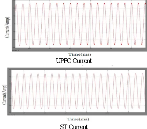
UPFC Current
.
ST Current
[image:8.612.186.426.498.709.2]Technology (IJRASET)
©IJRASET 2013: All Rights are Reserved
167
UPFC Voltage
In this case, the rating of the magnetic circuit of the ST is only 1.5 p.u. Note that the proper rating of the magnetic circuit of the VSC-based UPFC is 4.5 p.u. (shunt coupling transformer: 1 p.u.; shunt intermediate transformer: 0.5 p.u.; series coupling transformer: 2p.u.; and series intermediate transformer: 1 p.u.). The basic differences between the traditional technology of transformer and tap changer and the emerging technology of VSC are given in Table I. The advantage of the VSC-based UPFC is its ability to generate or absorb reactive power If needed, this capability of generation or absorption
ST Voltage
Fig.8(b).Comparison of voltage of the ST and the UPFC
Technology (IJRASET)
©IJRASET 2013: All Rights are Reserved
168
Fig.9(b). THD of Sen Transfromer(0.31%)
of reactive power can be utilized to regulate the bus voltage with the use of the shunt-connected VSC (STATCOM).In a stiff network, a STATCOM that is rated at changes the bus voltage less than 1%. In a UPFC configuration, the STATCOM has to let the active power of the series converter go through it first, thereby reducing its own reactive power- carrying and voltage- regulating capabilities . If the reactive power support is not essential, an ST offers the most cost-effective power flow solution. If additional shunt reactive power compensation is needed, an ST can be used in conjunction with a shunt reactive compensator.
VI. CONCLUSION
An ST that is based on the traditional technology of transformer and tap changers and a UPFC that is based on the emerging technology of VSC provide the same independent and bidirectional control of active and reactive power flow in an ac transmission line. The UPFC has the capability of providing fast dynamic response, but this capability in most utility applications is not required where the need is to regulate the line voltage and the power flow in a slow response (0.02ms). The speed of the tap changer operation in an ST provides adequate response time. The ST is an effective power-flow controller with an acceptable response time in most utility applications with presently available mechanical tap changers. The implementation of the tap-selection algorithm for the ST is much easier and economical in comparison to the UPFC control implementation The ST uses traditional components such as transformers and tap changers whereas the UPFC uses power-electronic based technology which requires high installation and operating costs. Therefore, the ST is an economical and effective alternative to the UPFC.
REFERENCES
[1] Salah Eldeen Gasim. M. H., Abdelaziz. Yousif. M. A. and Yousif Hassan. A., “Power System Contingency Analysis to detect Network Weaknesses,” ZEC Infrastructure 2012, June 18-20, 2012, Amman, Jordan
[2] M. Omar Faruque, Student Member, IEEE, and Venkata Dinavahi, Member, IEEEA “Tap-Changing Algorithm for the Implementation of “Sen” Transformer” IEEE TRANSACTIONS ON POWER DELIVERY, VOL. 22, NO. 3, July 2007
[3] Kalyan K. Sen, Senior Member, IEEE, and Mey Ling Sen, Member, IEEE “Comparison of the “Sen” Transformer With the Unified Power Flow Controller” IEEE TRANSACTIONS ON POWER DELIVERY, VOL. 18, NO. 4, OCTOBER 2003
[4] Varma, Rajiv K. “Elements of FACTS Controllers,” Transmission and Distribution Conference and Exposition, 2010 IEEE PES, pp. 1-6. IEEE, 2010. [5] Renz, B. A., A. J. F. Keri, A. S. Mehraban, J. P. Kessinger, C. D. Schauder, L. Gyugyi, L. J. Kovalsky, and A. A. Edris. "World‟s first unified power flow
controller on the AEP system." CIGRE paper 14-107, 1998.
[6] K. K. Sen and M. L. Sen, “Introducing the family of “sen” transformers: A set of power flow controlling transformers,” IEEE Trans. Power Del., vol. 18, no. 1, pp. 149–157, Jan. 2003.
[7] Salah Eldeen Gasim M. H. a, b, J. Jasni b, M. A. M. Radzi b, H. Hizamb “Power System Security Enhancement and Loss Reduction using the SMART Power Flow Controller”2014 IEEE Inovative smart grids-Asia
[8] EPRI, “Evaluate solid-state LTC options for medium power transformers: Project 41C3084/6658-6424,” Electric Power Research Inst., Palo Alto, CA, EPRI Tech. Rep. 1 000 916, Dec. 2000.
[9] Salah Eldeen Gasim Mohamed1 J. Jasni2, M. A. M. Radzi3, H. Hizam3, Maryam Mirzaei1 “Optimal Allocation of Sen Transformer for Active Power Loss Reduction”2014 IEEE International Conference Power and Energy(PECON)
[10] Kalyan K. Sen and Mey Ling Sen, “Introduction to FACTS Controllers,” 2009, The Institute of Electrical and Electronics Engineers, Inc.