5
III
March 2017
Technology (IJRASET)
Smart Locker System to Crack Shoulder Surfing
Techniques
Zulia Shanaz. F1, S. Raja2, Vidhya. S3 , Viji Priya. B4, Vinitha Sivaraj5, Yaaline K M6 1,2
Assistant Professor, 3,4,5,6UG Students , Dept. of ECE Sri Shakthi Institute of Engg and Technology, Coimbatore, TN, India.
Abstract: Authentication based on passwords is used largely in applications for computer security and privacy. The password is generated for each and every time a new color code is generated for the user. The user can open the locking system based on the color displayed in the matrix display. The colors are varied by using various color led and they can be randomly varied according to the user.
Keywords: Shoulder surfing, Boot loader, GPIO, Arduino UNO board.
I. INTRODUCTION
Traditionally, picture-based password color coding systems employ password objects (pictures/icons/symbols) as input during an authentication session, thus making them vulnerable to “shoulder-surfing” attack because the visual interface by function is easily observed by others. Recent software-based approaches attempt to minimize this threat by requiring users to enter their passwords indirectly by performing certain mental tasks to derive the indirect password, thus concealing the user’s actual password. However, weaknesses in the positioning of distracter and password objects introduce usability and security issues. In this paper, a new method, which conceals information about the password objects as much as possible, is proposed. Besides concealing the password objects and the number of password objects, the proposed method allows both password and distracter objects to be used as the challenge set’s input. The correctly entered password appears to be random and can only be derived with the knowledge of the full set of password objects. Therefore, it would be difficult for a shoulder-surfing adversary to identify the user’s actual password. Simulation results indicate that the correct input object and its location are random for each challenge set, thus preventing frequency of occurrence analysis attack. User study results show that the proposed method is able to prevent shoulder-surfing attack.
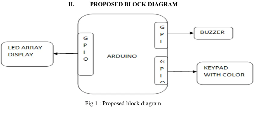
[image:2.612.102.525.454.648.2]II. PROPOSED BLOCK DIAGRAM
Fig 1 : Proposed block diagram
III. PROPOSED METHOD
Technology (IJRASET)
A. Arduino Microcontroller
[image:3.612.226.412.140.276.2]A micro-controller is a small computer on a single integrated circuit containing a processor core, memory, and programmable input/ output peripherals The important part for us is that amicro-controller contains the processor (which all computers have) and memory, and some input/output pins that you can control. (often called GPIO - General Purpose Input Output Pins).
Fig 2 : Arduino Microcontroller
This is a relatively easy way to make circuits quickly. Breadboards are made for doing quick experiments. They are not known for keeping circuits together for a long time. When you are ready to make a project that you want to stay around for a while, you should consider an alternative method such as wire-wrapping or soldering or even making a printed circuit board (PCB). The first thing you should notice about the breadboard is all of the holes.
IV. PROGRAMMING
The Uno can be programmed with the Arduino Software (IDE). For details, see the reference and tutorials. The ATmega328 on the Uno comes preprogrammed with a boot loader that allows you to upload new code to it without the use of an external hardware programmer. It communicates using the original STK500 protocol (reference, C header files). On Rev1 boards: connecting the solder jumper on the back of the board (near the map of Italy) and then rese in the 8U2.
On Rev2 or later boards: there is a resistor that pulling the 8U2/16U2 HWB line to ground, making it easier to put into DFU mode. You can then use Atmel's FLIP software (Windows) or the DFU programmer (Mac OS X and Linux) to load a new firmware. Or you can use the ISP header with an external programmer (overwriting the DFU boot loader). See this user-contributed tutorial for more information.
A. Warnings
The Uno has a resettable polypus that protects your computer's USB ports from shorts and overcurrent. Although most computers provide their own internal protection, the fuse provides an extra layer of protection. If more than 500 mA is applied to the USB port, the fuse will automatically break the connection until the short or overload is removed.
B. Differences with Other Boards
The Uno differs from all preceding boards in that it does not use the FTDI USB-to-serial driver chip. Instead, it features the Atmega16U2 (Atmega8U2 up to version R2) programmed as a USB-to-serial converter.
C. Power
Technology (IJRASET)
D. Memory
The ATmega328 has 32 KB (with 0.5 KB occupied by the boot loader). It also has 2 KB of SRAM and 1 KB of EEPROM (which can be read and written with the EEPROM library).
E. Input and Output
See the mapping between Arduino pins and ATmega328P ports. The mapping for the Atmega8, 168, and 328 is identical. Each of the 14 digital pins on the Uno can be used as an input or output, using pin Mode (), digital Write (), and digital Read () functions. They operate at 5 volts. Each pin can provide or receive 20 mA as recommended operating condition and has an internal pull-up resistor (disconnected by default) of 20-50k ohm. A maximum of 40mA is the value that must not be exceeded on any I/O pin to avoid permanent damage to the microcontroller. In addition, some pins have specialized functions:
1) Serial: 0 (RX) and 1 (TX). Used to receive (RX) and transmit (TX) TTL serial data. These pins are connected to the corresponding pins of the ATmega8U2 USB-to-TTL Serial chip.
2) External Interrupts: 2 and 3. These pins can be configured to trigger an interrupt on a low value, a rising or falling edge, or a change in value. See the attach Interrupt () function for details.
3) PWM: 3, 5, 6, 9, 10, and 11. Provide 8-bit PWM output with the analog Write () function.
4) SPI: 10 (SS), 11 (MOSI), 12 (MISO), 13 (SCK). These pins support SPI communication using the SPI library.
5) LED: 13. There is a built-in LED driven by digital pin 13. When the pin is HIGH value, the LED is on, when the pin is LOW,
it's off.
6) TWI: A4 or SDA pin and A5 or SCL pin. Support TWI communication using the Wire library. The Uno has 6 analog inputs,
labeled A0 through A5, each of which provide 10 bits of resolution (i.e. 1024 different values). By default they measure from ground to 5 volts, though is it possible to change the upper end of their range using the AREF pin and the analog Reference () function. There are a couple of other pins on the board:
7) AREF: Reference voltage for the analog inputs. Used with analog Reference ().
8) Reset: Bring this line LOW to reset the microcontroller. Typically used to add a reset button to shields which block the one on the board.
F. Communication
The Uno has a number of facilities for communicating with a computer, another Uno board, or other microcontrollers. The ATmega328 provides UART TTL (5V) serial communication, which is available on digital pins 0 (RX) and 1 (TX). An ATmega16U2 on the board channels this serial communication over USB and appears as a virtual com port to software on the computer. The 16U2 firmware uses the standard USB COM drivers, and no external driver is needed. However, on Windows, a .inf file is required. The Arduino Software (IDE) includes a serial monitor which allows simple textual data to be sent to and from the board. The RX and TX LEDs on the board will flash when data is being transmitted via the USB-to-serial chip and USB connection to the computer (but not for serial communication on pins 0 and 1. A Software Serial library allows serial communication on any of the Uno's digital pins. The ATmega328 also supports I2C (TWI) and SPI communication. The Arduino Software (IDE) includes a Wire library to simplify use of the I2C bus; see the documentation for details. For SPI communication, use the SPI library.
G. Automatic (Software) Reset
Technology (IJRASET)
the auto-reset. The pads on either side of the trace can be soldered together to re-enable it. It's labeled "RESET-EN". You may also be able to disable the auto-reset by connecting a 110 ohm resistor from 5V to the reset line; see this forum thread for details.
H. Revisions
Revision 3 of the board has the following new features
1) Pin Out: added SDA and SCL pins that are near to the AREF pin and two other new pins placed near to the RESET pin, the
IOREF that allow the shields to adapt to the voltage provided from the board. In future, shields will be compatible with both the board that uses the AVR, which operates with 5V and with the Arduino Due that operates with 3.3V. The second one is a not connected pin that is reserved for future purposes.
2) Stronger RESET circuit. 3) Atmega 16U2 replace the 8U2.
I. Pattern Lock
After finding the vulnerabilities and weaknesses of Pin and Alphanumeric locking scheme, an advanced an advanced scheme was introduced for security in smart- phones. Pattern security scheme gives a facility of complex formation or pattern to the user. It consist a User Interface having 9 dots arranged in 3*3 matrix. Instead of remembering passwords the user just have to remember the formation applied to lock the application. Even by using a 3*3 matrix of 9 blocks (dots) which gives a complex formation for higher security, I becomes very easy for the attackers (or the people around the user) to guess the pattern formation by continuously noticing the hand gestures when the user is applying the pattern to the locked application.
V. CONCLUSION
Typically the inbuilt features and various locking systems are providing security to the applications in the smartphones, but they are not up to the mark. They are vulnerable to smudge attacks and shoulder surfing, where the passwords can be easily determined. In this paper, we analyzed the problem in the current locking schemes used in the smartphones. By providing shuffling of the colored blocks in a circular form, it improves security and users convenience.
VI. ACKNOWLEDGEMENT
The authors would like to thank IBM software group, for offering ID software development tool for used in this work.
REFERENCES
[1] Prof. V.J. Kadam, Taj Mohammad A. Raheman, Ajinkya Ajagekar and Sushant B. Patil, “Shoulder shuffling free graphical locker for android graphical pattern
lock with text support for android devices", IJARCH, Volume 4, Issue 3. 2013.
[2] Deepika Jyoti and Dr. Amandeep Verma, “Enhancement of the security of pass-go pattern password using shuffling grid-shapes", IJIRCCE, Volume 2, Issue
11. 2014.
[3] Kwang Il Shin, Ji Soo Park, Jae Yong Lee and Jong Hyuk Park. “Design and implementation of improved authentication system for android smartphone users",
26th International Conference on Advanced Information Networking and Applications Workshops. 2012.