Technology (IJRASET)
Realization of Fixed-Point DLMS Adaptive Filter
Using VHDL
Ms. Thahseen Thahir#1, Mr. V Lakshmipathi#2, Dr. P. Ramamoorthy#3 #1
M.E VLSI Design, ECE Department, #2Professor &Head, #3ECE Department, Ph.D, Professor #2, #3
JCT College of Engineering & Technology, Pichanur, Coimbatore, Tamil Nadu #3
Adithya Institute of Technology, Coimbatore, Tamil Nadu
Abstract- During this paper, we tend to exhibit a productive engineering for the usage of a delayed minimum mean sq. adaptation filter. The smallest amount Mean sq. (LMS) adaptation filter is that the most prevailing and general adaptation filter, visible of its straight pushiness and satisfactory union execution. Succeeding this LMS calculation doesn't support pipelined execution on account of its dreary conduct; it's modified to a structure known as delayed LMS (DLMS) calculation. A deliberate structure for the execution of a DLMS adaptive filter is proposed in this paper. Existing DLMS filter utilizes carry look ahead adder as a part of request to perform the addition function which brought about area and power utilization issues. For accomplishing range power proficient execution, a swell carry adder is actualized over the tedious combinational squares of the current delayed LMS filter plan. From the design of the carry look ahead adder, it is clear that there is a probability for minimizing the area and power utilization in proposed structure. This work utilizes an uncomplicated and thriving door level amendment to basically diminish the realm and power. This filter set up offers less space delay product (ADP) and less energy delay product (EDP) than the most effective of this structures for filters N=8,16, and 32. Consequently it is clear that the aggregate range power utilization can be diminished to a more prominent degree utilizing the proposed strategy.
Keywords ̶ Adaptive filters, space Delay Product (ADP), Energy Delay Product (EDP), circuit optimization, fixed-point arithmetic, least mean sq. (LMS) algorithms.
I. INTRODUCTION
In signal preparing, filter is a gadget or procedure that expels from a signal some undesirable part or highlight. Separating is a class of signal handling, the characterizing highlight of filters being the finished or incomplete concealment of some part of the signal. Frequently, this implies evacuating a few frequencies and not others keeping in mind the end goal to smother meddling flags and diminish foundation clamor. Be that as it may, filters don't solely act in the recurrence area; particularly in the field of picture preparing numerous different focuses for separating exist. It is once in a while alluring to have circuits prepared to do specifically separating one recurrence or scope of frequencies out of a blend of various frequencies in a circuit. A circuit intended to perform this recurrence determination is known as a filter circuit, or just a filter. A typical requirement for filter circuits is in elite stereo frameworks, where certain scopes of sound frequencies should be opened up or stifled for best solid quality and power productivity. The equalizers, which permit the amplitudes of a few recurrence reaches to be changed in accordance with suit the audience's taste and acoustic properties of the listening zone. We are acquainted with hybrid systems, which hinder certain scopes of frequencies from achieving speakers. A tweeter (high recurrence speaker) is wasteful at imitating low recurrence flags, for example, rhythms, so a hybrid circuit is associated between the tweeter and the stereo's yield terminals to square low recurrence signals, just passing high recurrence signals to the speaker's association terminals. This gives better sound framework productivity and along these lines better execution. Both equalizers and hybrid systems are cases of filters, intended to finish sifting of specific frequencies.
II. ADAPTIVE FILTER
has expanded, adaptive filters have turned out to be significantly more regular and are currently routinely utilized as a part of gadgets, for example, cellular telephones and other specialized gadgets, camcorders and advanced cameras, and medicinal checking hardware.
III. LMS ADAPTIVE FILTER
An adjustive filter could be a procedure contraption that iteratively models the link between the data and yield signals of a filter. Associate adjustive filter self-changes the filter coefficients as per a adjustive calculation. The direct filter may be distinctive filter kinds, for instance, Finite Impulse Response (FIR) or Infinite Impulse Response (IIR). Associate adjustive calculation alters the coefficients of the direct filter iteratively to attenuate the facility of , wherever that is the mistake flag that indicates the excellence between further information signal and yield signal rule. The smallest amount Mean sq. adjustive Filter is way of the time knowledgeable about in wide assortment of utilizations like signal getting ready, estimation and investigation of endlessly dynamic parameters and signal examination. The immediate sort of LMS adjustive Filter doesn't support pipelining to its algorithmic conduct. During this method adjusted Delayed LMS adjustive Filter is favoured within which postpones area unit decayed so pipelining is connected to manage desirous squares.
IV. LMS ALGORITHM
The LMS calculation is an adaptive calculation among others which alters the coefficients of FIR filters iteratively. Other adaptive calculations incorporate the recursive minimum square (RLS) calculations. The LMS calculations are a class of adaptive filter used to imitate a coveted filter by finding the filter coefficients that identify with delivering the slightest mean squares of the mistake signal. Its straightforwardness and tasteful meeting execution made it prominent and subsequently broadly utilized. Different adaptive separating strategies that are utilized as a part of signal preparing application manage the hypothesis of adjustment with stationary signals notwithstanding the different adaptive calculations and structures. These adaptive separating systems are of high gear many-sided quality and expense.
V. PROPOSED ARCHITECTURE
A. Review of Delayed LMS algorithm
During the nth iteration the weights of LMS adaptive filter are updated according to the following equations:
w =w +μ·e ·x (1) where
e =d −y (2a)
y =w .x (2b) The input data , and the weight data at the iteration value are, given by
x = [x , x , . . . ,x −N+1] ; (3)
w = [w (0),w (1), . . . ,w (N−1)] (4)
d is the desired response, y is the output of filter, and e denotes the error calculated during the n iteration value. μ is the size of step, and N is the number of weights used in the LMS adaptive filter. In the case of pipelined design with m pipeline stages, the error becomes available after m cycles, where m is called the “adaptation delay”. The weight update equation of DLMS adaptive filter is given by
w =w +μ·e ·x (5)
Technology (IJRASET)
Fig.1. Block diagram of the traditional DLMS reconciling filter
Assuming that the latency of computation of error is cycles, the error computed by the structure at the cycle is ( ), which is used with the input samples delayed by cycles to generate the weight increment term. The weight update equation of the modified DLMS algorithm is given by
= +μ· · (6)
where
e =d - y (7)
and
= · (8)
There are two main computing blocks in the adaptive filter architecture: 1) The error computation block and 2) The weight update block. The style strategy of the planned structure is mentioned to minimize the adaptation delay in the error computation block, followed by the weight update block. Based on such a decomposition of delay, the modified DLMS adaptive filter can be implemented by a structure shown in Fig. 2.
The altered DLMS calculation decouples the blunder calculation piece and the weight-overhaul square and permits performing ideal pipelining by food forward slice set retiming to minimize the quantity of pipeline stages and adjustment delay. The adjustment delay gets diminished in DLMS because of its pipelined structure, yet in ordinary structure of DLMS, the systolic design is utilized such that there exist a high adjustment delay. We can see that amid weight adjustment, the blunder with n1 deferrals is utilized while the sifting unit utilizes the weights delayed by n2 cycles. By this approach the adjustment deferral is viably lessened by n2 cycles. In the following segment, we demonstrate that the proposed calculation can be actualized effectively with low adjustment delay which is not influenced considerably by the expansion in filter request.
Fig.2. Diagram of the changed DLMS reconciling filter
Notwithstanding, the movement adds operation to acquire the item esteem expands the word length, and subsequently builds the adder size of three options of the item values.
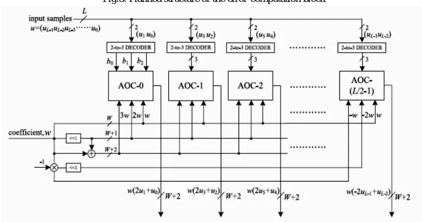
[image:5.612.185.441.178.358.2]To maintain a strategic distance from such increment in word size of the adders, we include all the four fractional results of the same spot esteem from all the four partial product generators by Ripple carry Adder tree. All the four halfway items produced by each of the four partial product generators are hence included by four parallel adder trees. Planned structure of the error computation block is given in Fig.3 and Fig.4 explains the planned structure of PPG. AOC stands for AND/OR cell
Fig.3. Planned structure of the error-computation block
Fig. 4. Planned structure of PPG. AOC stands for AND/OR cell
[image:5.612.96.515.373.594.2]Technology (IJRASET)
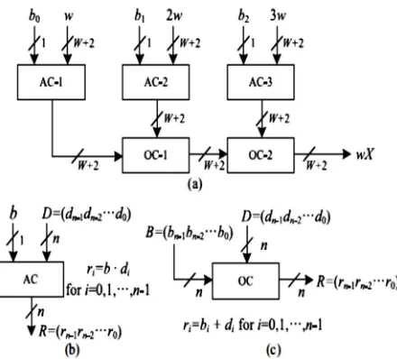
Fig.5. Structure and performance of AND/OR cell. Binary operators • and + in (b) and (c) area unit enforced exploitation AND and OR gates, severally.
3) Structure of Adder Tree: The movements include operation the halfway results of each PPG gives each of the item esteem and after that additional all the N item values to process the internal item yield. Be that as it may, the movement include operation acquires the item esteem which builds the word length, and the adder size. To stay away from expansion in word size of the adders, we include all the N incomplete results of the same spot esteem from all the N PPGs by a solitary adder tree.
The adder tree and shift–add tree calculation can be pruned for further improvement of territory, postpone, and power multifaceted nature. To decrease the computational multifaceted nature, a portion of the LSBs of inputs of the adder tree can be truncated and the gatekeeper bits can be utilized to minimize the effect of truncation on the blunder execution of the adaptive filter. To have more equipment sparing, the bits to be truncated are not created by the PPGs, so the multifaceted nature of PPGs additionally gets lessened. To have more equipment sparing, the bits to be truncated are not produced by the PPGs, so the many-sided quality of PPGs additionally gets reduced.
The location of pipeline latches for filter lengths N = 8, 16, and 32 and for input size L = 8 are shown in Table I. The pipelining is performed by a feed forward cut-set retiming of the error-computation block.
TABLE I. LOCATION OF PIPELINE LATCHES FOR L = 8 AND
N = 8, 16, 32
N
Error Computation Block WUB
Adder Tree
Shift - add Tree
Shift - add Tree
8 Stage 2 Stage 1 & 2 Stage 1
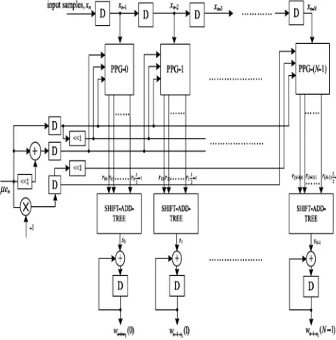
late accessible mistake by the movement operation. Every MAC unit performs the augmentation of the moved estimation of blunder with the delayed data tests took after by the increments with the relating old weight values . All the MAC operations are performed by N PPGs, trailed by N shift–add trees. Each of the PPGs creates L/2 fractional items comparing to the result of the as
[image:7.612.186.427.187.431.2]of late moved blunder esteem μ × e with the quantity of 2-bit digits of the information word . The sub expression can be shared over every one of the multipliers. This prompts a continuous diminishment adder in unpredictability. The last yields of MAC units constitute redesignaled weights to be utilized as inputs to the blunder calculation piece and the weight-overhaul hinder for the following.
Fig. 6. Modified structure of the weight-update block.
VI. FIXED-POINT IMPLEMENTATION, OPTIMIZATION, SIMULATION, AND ANALYSIS
In this section, we discuss the fixed point implementation and optimization of the proposed DLMS adaptive filter.
A. Fixed-point Design considerations
The altered point execution of the proposed DLMS adaptive filter demonstrates the bit level pruning of the adder tree, to lessen the equipment multifaceted nature without the corruption of relentless state MSE. For altered point execution, the word lengths and radix focuses for information tests, weights, and inward flags are should be chosen. Fig. 7 demonstrates the altered point representation of a double number. Table II demonstrates the altered representation of the fancied signals; its quantization is typically given as information. For this reason, the particular scaling/signal expansion and truncation/zero cushioning are required. Subsequent to the LMS calculation performs realizing so y has the same signal as d, deferred the mistake signal e can likewise be set to have the same representation as y without flood after the subtraction.
[image:7.612.194.420.628.689.2]Technology (IJRASET)
TABLE II FIXED-POINT REPRESENTATION OF THE SIGNALS OF THE PROPOSED DLMS ADAPTIVE FILTER (μ =
2−(Li+log2 N) )
Signal Name Fixed Point Representation
x (L, )
w (W, )
p (W+2, +2)
q (W+2+ N, +2+ N)
y,d,e (W, + + N)
µe (W, )
r (W+2, +2)
s (W, )
x, w, p, q, y, d, and e can be found in the error-computation block of Fig. 4. μe, r, and s are defined in the weight-update block in Fig. 8. It is to be noted that all the subscripts and time indices of signals are omitted for simplicity of notation.
VII. SIMULATION AND ANALYSIS
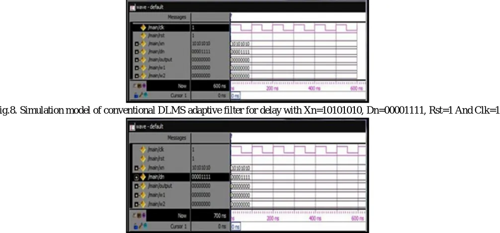
The simulation results are carried out for fixed-point LMS adaptive filter to find out the low adaptation delay. The simulation is carried out by the Modelsim 6.3f as a simulator tool. The performance of the delay block is simulated by giving various inputs to the weight-update block with various weights. Fig 8 and Fig.9 describes the simulation model & its waveform for delay with its weights w1, w2, w3, w4
To demonstrate the area and power comparisons of the proposed ripple carry adder we can simulate both of the carry look ahead adder and the ripple carry adder by using Xilinx 12.3 tool. Delayed LMS adaptive filter is synthesized in Spartan 2E starter board as the evaluation development board. The family is Spartan 3E, the device used is XC2S100E, the package is TQ144 and the speed is -6. The top level source type is HDL, the synthesis tool is XST (VHDL/Verilog), and the simulator is ISE Simulator (VHDL/Verilog). The power is calculated using XPOWER. The simulation results in detail are as follows.
[image:8.612.58.561.435.670.2]S.No Filter Area Power(mW) Memory usage (MB)
1 Existing
DLMS filter
12,131 98 171
2 Proposed
DLMS filter
8,173 67 169
Here the total gate count of delayed LMS filter using ripple carry adder is reduced to 8173 and memory usage is reduced to 169 MB while comparing it with delayed LMS filter using CLA adder. The total estimated power of filter using RCA is reduced to 67 mW while comparing with the filter using CLA adder.
VIII. CONCLUSION
A range power effective deferred LMS versatile filter utilizing swell carry adder is proposed. By utilizing this outline, we can include whole numbers of any size. The outline gives the benefit of effortlessness and requires least plan exertion which takes into account quick plan time. The configuration requires essentially less range and devours a great deal less power than the past outline. The most elevated examining rate that could be supported by the ASIC usage of the proposed outline ran from around 870 to 1010 MHz for filter orders 8 to 32.
At the point when the versatile filter is should have been be worked at a lower inspecting rate, one can utilize the proposed plan with a clock slower than the most extreme usable recurrence and a lower working voltage to decrease the power utilization further. Likewise, a substitution technique of swell carry expansion with 4:2 compressors is defeated advanced adjusted pipelining over the tedious pieces of the structure to lessen the power utilization definitely. The actualized adjusted DLMS structure included essentially less power. The execution of the power advanced changed DLMS engineering is done and the power, area and deferral parameters for the same are measured and dissected utilizing Xilinx ISE Design Suite 12.3. Power is diminished radically when the full adders are supplanted by 4:2 compressors.
REFERENCES
[1] S. Haykin and B. Widrow, Least-Mean-Square Adaptive Filters. Hoboken, NJ, USA: Wiley, 2003.
[2] S. Ramanathan and V. Visvanathan, “A systolic architecture for LMS adaptive filtering with minimal adaptation delay,” in Proc. Int. Conf. Very Large Scale
Integr. (VLSI) Designal, Jan. 1996, pp. 286–289.
[3] L. D. Van and W. S. Feng, “An efficient systolic architecture for the DLMS adaptive filter and its applications,” IEEE Trans. Circuits Syst. II, Analog Digital
Signal Process., vol. 48, no. 4, pp. 359–366, Apr. 2001.
[4] P. K. Meher and M. Maheshwari, “A high-speed FIR adaptive filter architecture using a modified delayed LMS algorithm,” in Proc. IEEE Int. Symp. Circuits
Syst., May 2011, pp. 121–124.
[5] K. K. Parhi, VLSI Digital Signal Procesing Systems: Designal and Implementation. NewYork, USA: Wiley, 1999.
[6] R. Rocher, D. Menard, O. Sentieys, and P. Scalart, “Accuracy evaluation of fixed-point LMS algorithm,” in Proc. IEEE Int. Conf. Acoust., Speech, Signal
Process., May 2004, pp. 237–240.
[7] L.-K. Ting, R. Woods, and C. F. N. Cowan, “Virtex FPGA implementation of a pipelined adaptive LMS predictor for electronic support measures receivers,”
IEEE Trans. Very Large Scale Integr.(VLSI) Syst., vol. 13, no. 1, pp. 86–99, Jan. 2005.
[8] S. Haykin (2002). Adaptive Filter Theory, 4th Edition, Prentice-Hall.
[9] L. Ting, R. Woods, and C. Cowan, “Virtex FPGA implementation of a pipelined adaptive LMS predictor for electronic support measures receivers,” IEEE
Transactions on Very Large Scale Integration (VLSI) Systems, vol. 13, no. 1, pp. 86–99, Jan. 2005.
[10] P. K. Meher and S. Y. Park, “Low adaptation-delay LMS adaptive filter part-I: Introducing a novel multiplication cell,” in Proc. IEEE Int. Midwest Symp.
Circuits Syst., Aug. 2011, pp. 1–4.
[11] P. K. Meher and S. Y. Park, “Low adaptation-delay LMS adaptive filter part-II: An optimized architecture,” in Proc. IEEE Int. Midwest Symp. Circuits Syst.,
Aug. 2011, pp. 1–4.
[12] Pramod Kumar Meher (2010) “Novel Input Coding Technique for High-Precision LUT-Based Multiplication for DSP Applications”, IEEE Transaction on
Embedded System, IEEE/IFIP International Conference on Very Large Scale Integration (VLSI) and System-On-Chip (SOC)., pp 201-206.
[13] Pramod Kumar Meher and Sang Yoon Park (2014)”Area-Delay-Power Efficient Fixed-Point LMS Adaptive Filter With Low Adaptation-Delay”, IEEE