6
I
January 2018
A Geometric Approach to Inverse Kinematics of a
3 DOF Robotic Arm
Ayush Gupta1, Prasham Bhargava2, Ankur Deshmukh3, Sankalp Agrawal4, Sameer Chourika5
1, 2, 3, 4, 5 Department of Electronics & Telecommunication, VIT, Pune
Abstract: In this paper, we develop and present a geometric approach to compute inverse kinematics for a 3 DOF robotic arm. Kinematics of a robotic arm deals with its motion with respect to a coordinate frame of reference without considering the effect of force. Inverse kinematics usually involves complex matrix operations to find the solution.
Using the geometric approach to find the solution results in faster computation over the conventional methods to find inverse kinematics solution. This simplified approach allows the implementation of the arm using a low-source micro controller. Keywords: Robotic arm, DoF, Forward Kinematics, Inverse Kinematics, Articulated Co-ordinate System, Robot Kinematics
I. INTRODUCTION
Forward and inverse kinematics are used to design any robotic system. The solutions obtained from forward and inverse kinematics define together how a system must be designed to effectively perform its operation. In forward kinematics, the values of all the joint variables are known and based upon on it the movement of the robotic arm takes place. The reverse mechanism is followed in in-verse kinematics. In inin-verse kinematics, the value of the joint variables is to be calculated based on the coordinates of the object to be reached by the arm. In general, the problems involving inverse kinematics are far more complicated to solve compared to the problem of forward kinematics.
Forward kinematics have an unique solution defined for them, unlike the case of inverse kinematics. Inverse kinematics usually have multiple solutions for the same given input. In some cases, it might even not have a result defined. There also exits situa-tions, where even though the solution exists, its unreachable by the arm, because the given coordinates fall outside the arms work-ing space. The most commonly used algorithm to find the solution of inverse kinematics problem is the Denavit-Hartenberg algo-rithm (D-H algoalgo-rithm), which involves several matrix transformations and therefore has a high computational complexity. Other algorithms include the geometric approach, which greatly reduces the computational complexity and hence enables the implementa-tion of the arm using simpler microcontrollers, which have a limited computaimplementa-tional capability.
This paper is organized as follows. Section II briefs about the literature review about various methods to compute forward and in-verse kinematics. Section III explains the proposed geometric method. Section IV presents the hardware and software setup of the robotic arm. Section V discusses about the future scope of the robotic arm. Section VI concludes the paper.
II.LITERATURESURVEY
Numerous methods have been proposed to compute the solution for forward and inverse kinematics for any robotic system. [1] Lukas Barnika and Roman Berka presented several ways to solve inverse kinematics problems which include the Jacobian inversion method, optimization based method, cyclic coordinate method (CCD), Genetic programming and the Jacobian based transpose method stating the advantages and disadvantages of each one of them. It also discusses the complexity of these methods due to the matrix operations involved in them. [2] Liu and Wang highlighted the complex numerical methods involved in finding solutions to inverse kinematics for a robotic system. They also proposed a geometric approach which can reduce the complexity involved in the computational task.[3] Alexandre
N. Pechev proposed a novel way of finding a solution to inverse kinematics without performing the operation of matrix inversion using feedback inverse kinematics method (or FIK) based on the feedback mechanism of a closed-loop system to find results to inverse kinematics problem.
III. PROPOSEDMETHOD
In this paper, a geometric approach to compute the inverse kinematics for a3 DoF robotic arm is presented.
For reducing the complexity, we reduce the problem to 3D from 2D. So, from Cartesian Co-ordinate system we converted the
problem to ρz co-ordinate system.
Fig.1. 2D representation of 3 DoF Articulated Robotic Arm
From the coordinate system transformation results we get,
= + = + +
Base = ta ( / )
From Cosine rule
= + −2 cos(180− )
Therefore,
Elbow = − ( + + −
2 )
From the figure 1, we know that,
= sin ( / )
and from trigonometry,
= tan ( ( )/( + ( ))
So,
Shoulder = + ( ( )
+ ( ))
where, base, shoulder, elbow is the joint angles x, y, z is the end-effector co-ordinates d1 and d2 are the lengths of the links.
Fig. 2. Figure showing the block diagram of Robotic Arm
IV. ROBOTIC ARM
The arm described possesses 3 DoF (degree of freedom). It is quite like a human arm with respect to number and positioning of joints. If the similarity is drawn between the joints of the robotic arm and the human arm, it can be seen the robotic arm has the fol-lowing joints: base (shoulder joint), elbow and wrist. Figure 2 shows the block diagram of the robotic arm. A scan be seen from the block diagram, the arms movement is being governed based on the computational results obtained by using forward and inverse kinematics. The user gives input in terms of the angles through which the motors must move in the case of forward kinematics. In the case of inverse kinematics, the coordinates where the object is placed are given as an input. The results computed by the soft-ware serves as an input to the microcontroller. The microcontroller decides how the three stepper motors must function and gives this an input to the motor driver. The motor driver then ensures the requisite amount of current is made available to all the motors.
A. Hardware setup
The actuators for all three joints are stepper motors. Of all the three motors used, the shoulder motor is the most powerful as it bears the load of the entire arm in addition to the load of the object to be picked and placed. Table 1 lists the different step-per motors used along with their torque ratings for each joint.
[image:4.612.165.444.447.504.2]TABLE I
Table Showing the Maximum Current Capacity And Torque For Each Motor
B. Specifications Of The Robotic Arm Are
1) Degree of freedom:3
2) Programming mode: Offline
3) Weight: 3.2Kg
4) Link lengths:
• Link 1: 150 mm
• Link 2: 130 mm
The frame of the robotic arm is constructed using aluminum links.
The microcontroller used is Arduino (ATmega2560). It consists of 54 digital I/O pins (of which 15 provide PWM output) and 16 are analog input pins.
Joint Current Capacity(maximum) Torque (Kg-cm)
Base 2.8 10.0
Shoulder 2.8 18.0
The microcontroller receives its input from the Processing software serially. Serial input is in the form of a string which con-tains the values of the angles. Microcontroller first decodes the string and calculates the desired number of steps for each motor and passes it to motor driver through digital pins. The total number of outputs from the micro controller are nine, three for each motor.
Fig. 3. Figure showing the Robotic Arm
[image:5.612.168.410.136.319.2]TABLE II
TABLE SHOWING THE STEP ANGLE FOR THE SELECTED MICRO-STEP
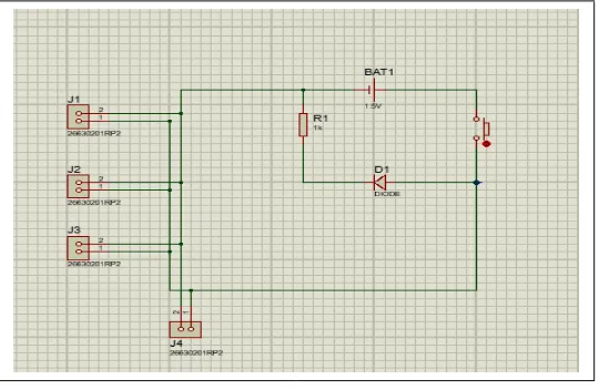
The next section is the motor driver. The motor driver used is TB6560 which has a maximum current capacity of 3A. This motor driver is selected since it meets the current requirement of the motors used in the arm. The motor driver is responsible for ensuring that the requisite amount of current is made available to the motors. The direction input simply governs the direction in which the motor rotates. The next section in the hardware setup is the power supply. To meet the power requirements, a separate power supply Section is designed for the arm. Figure4 shows the circuit for the power supply. As can be seen, the power supply consists of 4 ter-minals T1, T2, T3, and T4 which are connected in series with the DC supply. The main switch M turns ON or OFF the entire sup-ply. LED is connected in series with the power supply to indicate the state of power supsup-ply. A resistor is connected in series with the led to control the flow of current through led.
Micro-Step
Step An-gle
1 1.8
2 0.9
4 0.45
8 0.225
16 0.1125
Fig. 4. Figure showing the motor diagram connection diagram with the controller
Fig. 5. Figure showing the power supply circuit
It consists of three inputs: Enable (EN), Clock (CLK) and direction (DIR). The enable pins are used to enable or disable a motor. The clock is used to count the number of steps the motor should move to get the same angle as desired by the user.
The driver serves an interface between the motor and the controller as it receives a signal from the controller and then sends it to the motor in the desired form (voltage & current rating of the motor). The driver also provides the micro-step function, which when altered can control the value of the step angle and hence can provide for higher precision. The user enters the value of the angle and then the number of steps is given by:
C. Software setup
The Arduino IDE is used to program the microcontroller. The software used for computing forward and inverse kinematics is processing.
1) Forward Kinematics: In the forward kinematics mode, the software takes the angles by user and passes it to the con-troller, controller then counts the number of step by which the motors must be moved. The calculation is performed
step angle of the motor
[image:6.612.186.456.307.483.2]Fig. 6. Figure showing the Flow Chart for Forward Kinematics
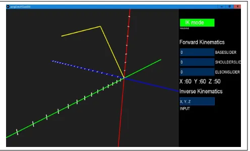
[image:7.612.152.495.69.199.2]2) Inverse Kinematics: In the inverse kinematics mode, the user gives the coordinates of the object as an input to the processing software. These coordinates are defined with respect to the base coordinate system which has its origin defined at the base of the robotic arm. Based on the geometric approach defined in the previous section, the angles by which each motor must move are com-puted. These angles then go as an input to the microcontroller and the movement of the arm takes place. Figure 7 depicts the entire procedure in the form of a flowchart.
Fig. 7. Figure showing the Flow Chart for Inverse Kinematics
VI. CONCLUSION
[image:7.612.193.441.551.701.2]A geometric approach to calculate the inverse kinematics solution for a 3 DOF arm along with its working mechanism was suc-cessfully implemented. The arm is developed by integrating the software setup with the hardware setup. The user gives the posi-tion of the object as an input which gets processed by the software. The software computes the output using either the forward or inverse kinematics based upon the nature of input. The geometrical approach greatly reduces the complexity involved in the calculations of inverse kinematics and hence also reduces the computational time. This simplified graphical approach enables the controlling of the arm using Arduino, since complex matrix operations involved in finding out the inverse kinematics are being eliminated. The same method can be extended to arms with higher values of DoF.
Robotic Arm is denoted by the yellow color lines in t processing software. The three axes are denoted by green, blue and red (x, y, z) colors respectively.
V. FUTURESCOPE
The arm can be automated by making the use of sensors. Sensors which can compute the distance between the object and the arm can be used which will give feedback to the micro controller unit. Based on the feedback obtained the micro controller decides the movement of the motors to efficiently pick and place the object.
REFERENCES
[1] L. Barinka, Ing. Roman Berka” Inverse Kinematics - Basic Methods”, ”http://old.cescg.org/CESCG-2002/LBarinka/paper.pdf”.
[2] Y. Liu, D. Wang” Geometric Approach for Inverse Kinematics Anal- ysis of 6-Dof Serial Robot” International Conference on Information andAutoma-tionLijiang,China,August2015.
[3] AlexandreN.Pechev,InverseKinematicswithoutMatrixInversion, IEEE 2008 International Conference on Robotics and Automation
[4] Krzysztof Tokarz and Slawosz Kieltyka, Geometric Approach to Inverse Kinematics for Arm Manipulator, Latest Trends on System Vol.2
[5] Krzysztof Tokarz and Christian Manger, Geometric and Rough Set Approach to Inverse Kinematics for Arm Manipulator, International JournalofMath-ematicalModelsandMethodsinAppliedSciences
[6] S. Cavalcanti, O. Santana” Self-learning in the inversekinematics of robotic arm” Robotics Symposium (LARS) and 2017Brazilian Symposium on Robotics (SBR), 2017 Latin American, November 2017
[7] A.Bhargava,A.Kumar” Arduinocontrolledroboticarm”International conference of Electronics, Communication and AerospaceTechnology (ICECA), April2017
[8] OpenGL:”https://www.opengl.org/documentation”. [9] Arduino:”https://www.arduino.cc”.