Voltage Control of Synchronous Generator Using
PID -Fuzzy Logic Controller
C. Mohan Krishna1 T.Manohar2, DR. G. Satheesh Reddy3 1, 2
Assistant Professor in Ananthalakshmi college of Engineering 3
Associate professor in G.Pullareddy Engineering College
Abstract:This work aims to develop a PID controller tuned FUZZY controller, it functions such as maintaining of the terminal
voltage of the synchronous generator constant even for the change in load, this is achieved by varying the field current flowing through the field coils of synchronous generator. It includes simulations for the justification of this design in MATLAB. The traditional PID control structure is simple, has a certain robustness, and can achieve better control effect, but because the traditional PID controller needs to manually adjust the parameters, so that the generator excitation adjustment process is more complicated and inconvenient. FLC is the fuzzy logic control, which is characterized by the non dependent control object’s mathematical model, and the design method is simple and has strong adaptability, and is easy to implement [1]. After the theoretical analysis is completed, matlab simulation software is adopted in simulation, in which a satisfying effect has been achieved. In other words, PID-FLC based on generator’s excitation control system is more effective than the traditional PID excitation control system.
Key words: PID controller, Fuzzy controller, Synchronous generator.
I. INTRODUCTION
The problem of voltage control in the system consists of the voltage control at the generating station in the system, i.e., voltage control of generators and transmission lines. The voltage of ac generators is controlled by voltage regulators working on electro mechanical principle such as vibrating type regulator in which a fixed amount of resistance is cut in and cut out on the exciter field circuit, depending on the alternator voltage variation to maintain it constant. the main importance of this paper is to design a controller to overcome the difficulties of complex mathematical model of the plant to be controlled, and to develop an intelligent control system, so that the regulator becomes independent of the system to be controlled and it generates controlling signals on the
bases of experiences it faces during the operation.This critique work carried out for the problem of load change on the synchronous
generator and studies the terminal voltage variation with load change. The objective of the present work is
Maintain the terminal voltage of the synchronous generator constant inspite of the load change on it.
Run the synchronous generator in stable region i.e., limiting the transient state to last only few milliseconds when the load changes occur on the synchronous generator.
A. Proposed system
In large alternators, the excitation system is provided by a small synchronous machine connected on the same shaft as the main synchronous generator. Current rectification is performed by a rotating diode bridge mounted on the synchronous machine shaft, thus avoiding slip rings for providing DC power to the synchronous generator field. Mechanical coupling of the Synchronous generator and the Exciter is done by using speed as mechanical input for the Exciter machine. The Exciter is a small synchronous machine rated 8.1 kVA, 400 V, 50Hz, 1500 RPM. The Exciter output voltage would be 12 V. The output of the rectifier bridge is
Fig: 1. Block diagram of proposed system
Connected directly to the Synchronous generator field terminals. Filtering is not required because of the large field inductance. The synchronous generator is
a 2 MVA, 400V, 50 Hz, 1500 RPM machine driven by a diesel motor. A nominal field current of 100A specified in the mask parameters allows using the real voltage applied to the rotor (not the field voltage seen from stator). It results in a nominal field voltage of 9.2837V.
The voltage appearing across current source corresponds to the field voltage which must be applied to the field connections of Synchronous Machine input.
II. DESIGNOFCONTROLSYSTEMFORVOLTAGECONTROL:
To design a regulator control system in such a manner to overcome the difficulties of complex mathematical model of the plant to be controlled, and to develop an intelligent control system, so that the regulator becomes independent of the system to be controlled and it generates controlling signals on the bases of experiences it faces during the operation. Also the system should be very simple to understand, and easy to program.
A. Pid Controller
Regulator control systems mostly use PID controllers which are given by equation shown below
GC(S)=KP+KI/S+KDS
PID controllers are commonly used in industry and a large factory may have thousands of them, in instruments and laboratory equipment. In engineering applications the controllers appear in many different forms: as a standalone controller, as part of hierarchical, distributed control systems, or built into embedded components. Most controllers do not use derivative action. The ideal version of PID controller is given by
t) =Kpe (t) +Ki +Kd
Where u is the control signal and e is the control error (e = r(t) – y(t)). The reference value, r, is also called the set point. The control signal is thus a sum of three terms: a proportional term that is proportional to the error, an integral term that is proportional to the integral of the error, and a derivative term that is proportional to the derivative of the error. The controller parameters are proportional gain kp, integral gain ki and derivative gain kd. The transfer function of the PID Controller is shown below
is necessary. In case of digital PID controllers, the multiplication, integration and differentiation are performed numerically in digital computers. Users of control systems are frequently faced with the task of adjusting the controller parameters to obtain a desired behaviour. There are many different ways to do this. One way to do this is to go through the steps of modelling and control design. Since the PID controller has so few parameters a number of special empirical methods have also been developed. A simple idea is to connect a controller, increase the gain until the system starts to oscillate, and then reduce the gains by an appropriate factor. Another is to measure some features of the open loop response and to determine controller parameters based on these features. The PID controller is designed by using Ziegler and Nichols method.
Table: 1. Default parameters of PID controller
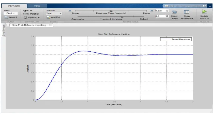
Fig 2. PID response for default parameters
The role of the correction link is: Proportional links: the proportion of the control system to reflect the deviation of E(T), once produced, the controller immediately to produce control to reduce the deviation. Integral link: mainly used to eliminate static error, improve the system of no difference. The integral function of the strength is the integral time constant T, T is more, the integration of the more weak, the smaller the T, the more integral role. Differential link: the change trend of the deviation signal, and can be introduced into the system in order to get a valid early correction signal, so as to speed up the system’s movement speed and reduce the adjustment time
B. Fuzzy logic
Fuzzy logic controllers are designed particularly for non-linear dynamic systems with many inputs and outputs which are so complex, that it is very difficult or even impossible to build exact mathematical model. Controllers of this type are characterized by large number of parameters, like: number and form of fuzzy sets used for division of computational domain of input and output signals, selection of operators for realizing fuzzy operations as sum, product and negation, selection of conclusion algorithm, choice of function for computing numerical values of output signals. These parameters must be adjusted and given the correct values in order to the controller work properly. Application of fuzzy logic in control process requires using the following elements: definitions of fuzzy sets, fuzzy logic operators, fuzzy rules (rule database), inference mechanism and algorithm of computing numerical values of output signal. Fuzzy control is a complex system which is difficult to describe. The computer control technology based on natural language and fuzzy reasoning is not dependent on the traditional mathematical model, but is dependent on the fuzzy rules by the operation experience and the expression of knowledge. The basic flow chart of the fuzzy controller is
Controller Kp/kc Ti/Tc Td/Tc Tp/Tc
P 0.5 1.0
PI 0.4 0.8 1.4
[image:4.612.117.459.290.473.2]shown in Figure 2. This framework contains 5 important parts, that is, the definition of variable, fuzzy, knowledge base, logical reasoning and anti-mode. Defining variables: that is, the state of the program is observed and the action to consider. For example, the input variable is CE and the output error is u, while the control variable is the next state. Where e, CE, u are collectively referred to as fuzzy variables. Fuzzy: the input values are converted to the numerical value of the domain of the input values. The process of measuring the physical quantity is expressed by using the colloquial variables. The relative membership degree is obtained according to the appropriate language value. Knowledge base: including two parts, including database and rule base, where the database is to provide the relevant definitions of processing fuzzy data, and the rule base is a group of language control rules to describe the purpose and strategy. Logical reasoning: the fuzzy concept of imitating human judgment, fuzzy logic and fuzzy inference, fuzzy control signal. Anti-mode: the fuzzy transformation from the inference to the explicit control signal as the input value of the system. Fuzzy control depends on the “fuzzy rules”, which is a scientific and reasonable way to combine the fuzzy control with the excitation control of generator.
B.1 Fuzzy Memberships:
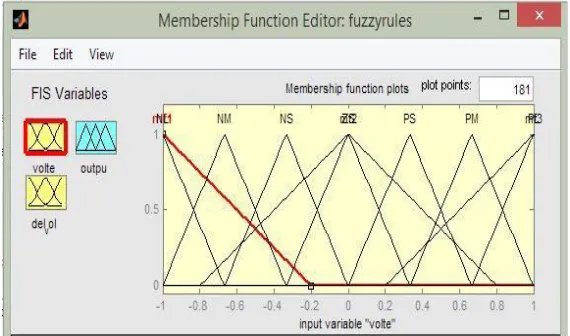
[image:5.612.161.446.448.616.2]Membership function values are assigned to the linguistic variables, using seven fuzzy subsets: NB (Negative Big), NM (Negative Medium), NS (Negative Small), ZE (Zero), PS (Positive Small), PM (Positive Medium), and PB (Positive Big).
Table 2. System Parameters when using PID Controller
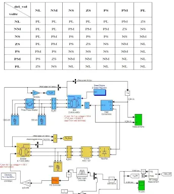
1) 2 Fuzzy Rules: Several composition methods such as Max–Min and Max have been proposed in the literature. In this paper Min method is used. The output membership function of each rule is given by the minimum operator and maximum operator. Table shows rule base of the FLC
Fig 3. Graph showing various membership functions
C. Simulation Analysis
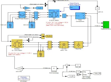
1) CASE I: Proportional Integral Derivative Controller:In this case, we use the proportional integral derivative (PID) controller to control the excitation voltage of the synchronous generator . The proportional gain is set to 4, integral gain is set to 5, derivative gain is set to 0.1. In this circuit, we are mainly using PID controller, speed governor for prime mover (diesel generator),rectifier to convert ac obtained from the main synchronous machine to dc which is applied to rotor, another small synchronous machine which is acting as a exciter, 500kw base load and extra 1000kw load is taken into circuit with the help of circuit breaker closing.
SYSTEM PARAMETERS VALUES
Main synchronous machine 2MVA
Exciter 8.1 KVA, 400V
Primary load 50KW
Secondary load 1000KW
Proportional gain 4
Integral gain 5
Fig 4: simulation using pid controller
1) Case ii: PID controller along with fuzzy logic: In this case, we use the proportional integral derivative (PID) controller along with the fuzzy logic to control the excitation voltage of the synchronous generator. The proportional gain is set to 4, integral gain is set to 5, and derivative gain is set to 0.1. In this circuit, we are mainly using PID controller, fuzzy logic controller, speed governor for prime mover (diesel generator), rectifier to convert ac obtained from the main synchronous machine to dc which is applied to rotor, another small synchronous machine which is acting as a exciter, 500kw base load and extra 1000kw load is taken into circuit with the help of circuit breaker closing.
SYSTEM PARAMETERS VALUES
Main synchronous machine 2MVA
Exciter 8.1 KVA, 400V
Primary load 50KW
Secondary load 1000KW
Proportional gain 4
Integral gain 5
Derivative gain 0.1
Membership functions 7
Membership function Limit [-1 1]
Fig 5: simulation using fuzzy PID controller
D. Simulation results 1) CASE I: PID Controller
[image:7.612.86.491.528.716.2]The above figure shows the terminal voltage of the synchronous generator measures in per unit for a base value of 400 volts. Assuming steady state before 3 sec, extra load of 1000KW is added on to the synchronous generator. This cause disturbance on the generator causing the terminal voltage deviates from the reference voltage (1 pu). It again gains its steady state after 3 sec at 7 sec time. The constant steady state error is almost zero. The shaft speed reaches the reference speed after 3 sec of adding of the 1000 KW load on to synchronous generator.
Fig. 7 Exciter Voltage and Exciter Current
The above figure shows the change in the exciter voltage when the load is added at 4 sec. It takes relatively long time to stabilize the exciter voltage but with a more voltage compared to the same and the stator current of the main synchronous generator. Initially when the load is at 4 sec, the stator current gets excess than what it need to be and decreases after 2 sec.
CASE II: PID Controller Along With Fuzzy Logic:
In this case, we use the proportional integral derivative (PID) controller along with the fuzzy logic to control the excitation voltage of the synchronous generator. The proportional gain is set to 4, integral gain is set to 5, and derivative gain is set to 0.1. In this circuit, we are mainly using PID controller, fuzzy logic controller, speed governor for prime mover (diesel generator), rectifier to convert ac obtained from the main synchronous machine to dc which is applied to rotor, another small synchronous machine which is acting as a exciter, 500kw base load and extra 1000kw load is taken into circuit with the help of circuit breaker closing.
[image:8.612.128.480.491.707.2]Fig 9. Shaft speed
The shaft speed reaches the reference speed after 2 sec of adding of load with much less oscillations compared to previous cases and settle to reference speed with a much lesser time delay.
Fig10: Exciter voltage
The above figure shows the exciter voltage change when the load is added at 4 sec before which the exciter is in steady state. It takes approximately a little more than 1 sec to stabilize the exciter voltage
Fig11. Exciter current
III. CONCLUSIONANDFUTURESCOPE
This paper includes a custom made PID Controller along with Fuzzy Logic to improve the performance of the synchronous generator. The performance improvement parameters include the following.
A. Maintaining of the terminal voltage of the synchronous machine constant and unaffected by the load variations on it.
B. Supply of the required field current through the field coils to have a stable magnetic coupling between stator and rotor.
C. Maintain the load angle within specified limits so as to run the synchronous generator in stable condition.
Addition of the new Proportional Integral Derivative controller along with the Fuzzy Logic for the control of the field voltage of the exciter adjusts the field voltage to exciter according to the rules specified for the fuzzy supporting in addition to PID Controller regulates all the above mentioned parameters indirectly or directly.
The proposed controller could also be used for control of speed of the shaft of the generator in place of the governor for the turbine to further more increase the effective performance of the synchronous generator. Other controlling techniques such as use of genetic algorithm, artificial neural networks, artificial intelligence can be used along with fuzzy logic or in place of fuzzy logic to increase the effectiveness of the controller in improving the parameters.
REFERENCES
[1] Anant Oonsivilai ,Padej Pao-la-or, " Optimum PID Controller tuning for AVR System using Adaptive Tabu Search " , School of Electrical Engineering, Suranaree University of Technology, Nakhon Ratchasima, Thailand.
[2] Ritu Shakya, Kritika Rajanwal, " Design and simulation of PD, PID and Fuzzy Logic Controller for Industrial Application " , SRMSCET, Bareilly, India. [3] O ' Dwyer , Aidan, " Performance improvement using simple PID controller tuning formulae " , Proceedings of 3rd IET International Conference on Power
Electronics, Machine and Drives, Dublin.
[4] A. H. Besheer, A. Bensenouci, “Voltage and Power Regulation for a Sample Power System using Ant Colony System Based PID Controller” , International Electrical Systems, J. Electrical Systems 8-4 (2012):397-410
[5] Habibur Rahman, Dr. MD. Fayzur Rahman, “Stability Improvement of Power System by using SVC with PID Controller " , ISSN 2250-2459, VOL. 2, Issue 7, July 2012.
[6] Kiyong Kim, Richard C. Schaefer, " Tuning a PID Controller for a Digital Excitation Control System " , IEEE Transactions on Industry Applications, VOL. 41, NO. 2, March/April, 2005.
[7] Gowri Shankar Kasilingam and Jagadeesh Pasupuleti, " Tuning of PIC Controller for a Synchronous Machine Connected to a non-linear load " , ARPN Journal of Engineering and Applied Sciences " , VOL. 9, NO. 9, September 2014.