-
/
I
DR
Draw
,
-...
..~.
--DR Draw™
Graphic Application
[!ill
DIGITAL
RESfARCH®
DR Draw™
Graphic Application
COPYRIGHT
Copyright © 1984 by Digital Research Inc. All rights reserved. No part of this publica-tion may be reproduced, transmitted, transcribed, stored in a retrieval system, or translated into any language or computer language, in any form or by any means, electronic, mechanical, magnetic, optical, chemical, manual or otherwise, without the prior written permission of Digital Research Inc., Post Office Box 579, Pacific Grove, California, 93950.
Preliminary versions of software and documentation for DR Draw were acquired through a technology exchange agreement with TeleVideo Systems Incorporated of Sunnyvale, California.
DISCLAIMER
Digital Research Inc. makes no representations or warranties with respect to the contents hereof and specifically disclaims any implied warranties of merchantability or fitness for any particular purpose. Further, Digital Research Inc. reserves the right to revise this publication and to make changes from time to time in the content hereof without obligation of Digital Research Inc. to notify any person of such revision or changes.
NOTICE TO USER
From time to time changes are made in the filenames and in the files actually included on the distribution disk. This manual should not be construed as a representation or warranty that such files or materials and facilities exist on the distribution disk or as part of the materials and programs distributed. Most distribution disks include a "README.DOC" file. This file explains variations from the manual which do consti-tute modification of the manual and the items included therewith. Be sure to read this file before using the software.
TRADEMARKS
Digital Research and its logo are registered trademarks of Digital Research Inc. DR Draw is a trademark of Digital Research Inc.
The DR Draw Graphic Application User's Guide was printed in the United States of America.
First Edition: Second Edition: Release:
January 1984 March 1984
Foreword
INTRODUCTION
STRUCTURE OF THIS MANUAL
This manual teaches you how to produce a wide range of presentation-quality graphics with DR Draw TM, including
organizational charts, flow charts, structured analysis dia-grams, and line illustrations. You can display pictures cre-ated with DR Draw on color and monochrome display monitors, or you can use a printer, plotter, or camera to present your pictures on paper, transparencies, or print or slide film.
The DR DrawT
" Graphic Application User's Guide
con-tains six sections and two appendixes.
• Section 1 is a brief overview of DR Draw, after which you begin the first of two tutorials.
• Section 2 is a beginning tutorial in which you draw a basic organizational chart and a graphic design that you might use for a report cover.
• Section 3 is an advanced tutorial in which you modify and embellish the designs you created in the beginning tutorial.
• Section 4 describes several concepts that are fun-damental to DR Draw.
• Section 5 describes each of DR Draw's functions in alphabetical order.
• Section 6 describes DR Draw's seven design elements, also in alphabetical order.
• Appendix A describes the font library, which lets you enter text in several different type styles, including Ro-man, italic, script, Greek, and gothic fonts.
• Appendix B describes error messages that you might see while starting or using DR Draw.
CONVENTIONS
ILLUSTRATIONS
This manual uses several conventions involving capitaliza-tion and colored type.
In the text, DR Draw's functions, design elements, and layouts are capitalized, although they are not capitalized in the menus you see on your display monitor. For example, the text refers to the COPY function, the POLYGON de-sign element, and the PORTRAIT layout. Functions, in-cluding LAYOUT, are described in Section 5; design ele-ments are described in Section 6.
To help you identify filenames and filetypes (like CHART.PIX), they are capitalized in the text and in exam-ples of prompts and messages. However, you need not capitalize filenames when you use DR Draw.
The names of three keystrokes, PICK, DONE, and RE-TURN, are also capitalized in the text.
DR Draw's menus and submenus appear with initial capi-talization. You will see references to the Main Menu, Edit Menu, and Change Submenu, among others.
Examples of DR Draw's prompts and messages appear in Dot Matrix colored type. User input appears in Oblique colored type.
The figures in this user's guide were produced with DR Draw.
RELATED PUBLICATIONS
Before you start to use DR Draw, be sure you read the DR Draw User's Guide Supplement (cited as Supplement in this manual) you received with DR Draw. The Supplement describes how to copy your DR Draw diskettes, format a picture file diskette, and start DR Draw. It also provides information about the devices you can use with DR Draw.
In addition, you should be familiar with your hardware and software. For information on the particulars of your system, refer to the documentation that came with your computer, display monitor, printer, plotter, camera, and mouse.
Table of Contents
1 Overview
Introduction ... 1-1 Your Computer ... 1-1 Capabilities ... 1-2 Using This Manual ... 1-3 Using Keyboard or Mouse ... 1-3 DR Draw Menus ... 1-4 Menu Map ... 1-4
2 Getting Started
Introduction ... 2-1 Start DR Draw ... 2-1 Create A Chart ... 2-2 Main Menu ... 2-3 Moving Through The Menu ... 2-3 PICK ... 2-4 Create A Picture File ... 2-4 Draw Elements ... 2-6 RETURN and DONE ... 2-6 Draw Lines ... 2-6 Delete and Undelete ... 2-11 Copy Elements ... 2-12 Move Elements ... 2-14 Change Grid Size ... 2-15 Add Text ... 2-16 Change Text Style ... 2-19 Add More Text ... 2-19 Change Grid ... 2-22 Add Lines ... 2-22 Save A Picture ... 2-25 Check Directory ... 2-26 Recall Picture File ... 2-26 LAyOUT ... 2-27 ZOOM FULL ... 2-30 Rename Picture File ... 2-31 Print Picture ... 2-32 Create A Design ... 2-34
Table of Contents
(continued)
Create A Picture File ... 2-35
Draw Circle ... 2-36
Add Polygon ... 2-38
Add Another Polygon ... 2-40
STyLE ... 2-40
Bars ... 2-42
COLOR (Optional) ... 2-44
Changing Color ... 2-45
Arcs ... 2-46
Save The Picture ... 2-47
Exit DR Draw ... 2-48
3 Advanced Tutorial
Introduction ... 3-1
Recall The Picture File ... 3-1
PAN ... 3-2
COpy ... 3-4
Add and Change Text ... 3-8
Add Lines ... 3-12
Change Line Style ... 3-16
LAYOUT and ZOOM FULL ... 3-16
Add A Title ... 3-16
SAVE ... , ... 3-17
Report Cover Design ... 3-17
Recall Picture File ... 3-17
DELETE and SELECT ... 3-19
ZOOM OUT ... 3-21
Change Element Scale ... 3-21
Add Border ... 3-23
ZOOM IN ... 3-29
Add Three Arcs ... 3-32
Background Element ... 3-37
Change Style ... 3-38
PUT TO BACK ... 3-39
Add Title ... 3-40
Save The Drawing ... 3-42
Table of Contents
(continued)
4 Concepts
Introduction ... 4-1 DR Draw Menus ... 4-1 Main Menu Functions ... 4-2 Edit Menu ... 4-3 Submenus ... 4-4 Prompts and Messages ... 4-4 Error Messages ... 4-4 Drawing Surface ... 4-5 Window and Window Frame ... 4-6 Grid and Snap ... 4-6 Cursors ... 4-7 Menu Cursor ... 4-7 Menu Cursor: Wrapping ... 4-8 Graphics Cursor ... 4-8 Graphics Cursor: Range of Motion ... 4-8 Graphics Cursor: Mouse ... 4-8 Graphics Cursor: Keyboard ... 4-8 Graphics Cursor: Speed and Distance ... 4-9 Text Cursor ... 4-9 Current Element ... 4-9 Extent ... 4-10 Shared Extents ... 4-10 Style ... 4-11 Initial Style ... " .... ', ... 4-11 Changing Style ... 4-11 Current Style ... 4-12 Open and Filled Design Elements ... 4-12 Hollow Fill ... 4-13 Filenames ... 4-14 Illegal Characters ... 4-14 Filetype ... 4-14 Active Picture Files ... 4-15 Created and Recalled Files ... 4-15 Abandoning an Active File ... 4-16 Picture File Diskettes ... 4-16 Disk Drive Identifier ... 4-16 Disk Drive Identifier in Messages ... 4-16
Table of Contents
(continued)
5 Functions
Introduction ... 5-1 Change Submenu ... 5-2 Prompts ... 5-2 Error Messages ... ~ ... 5-2 ADD ... 5-3 CHANGE ... 5-4 COLOR ... 5-5 COpy ... 5-6 CREATE ... 5-8 DELETE ... 5-10 DIRECTORY ... 5-12 EDIT ... 5-13 EXIT ... 5-14 GRID ... 5-15 LAyOUT ... 5-18 MOVE ... 5-20 OUTPUT ... 5-21 RECALL ... 5-24 REDRAW ... 5-28 SAVE ... 5-29 SCALE ... 5-31 SELECT ... 5-36 STyLE ... 5-40 UNDELETE ... 5-42 VIEW ... 5-44
6 Design Elements
Introduction ... 6-1 Add Submenu ... 6-1 Prompts ... 6-2 ARC ... 6-3 BAR ... 6-6 CIRCLE ... 6-7 LINES ... 6-9 MARKERS ... 6-11 POLYGON ... 6-12 TEXT ... 6-14
Table of Contents
(continued)
Appendixes
A Font Library
Introduction ... A-1 Copy Your Diskette ... A-1 Program Diskette and Default Fonts ... A-1 Font Library Files ... A-3 Changing Fonts ... A-5 Style Submenu for TEXT ... , A-5 Fonts and Picture Files ... A-6 Erasing Font Files ... A-7 Restoring Fonts to the Defaults ... A-7 Font Character Sets ... A-7
B Additional DR Draw Error Messages
Introduction ... B-1 Starting DR Draw ... B-1 Using DR Draw ... B-3
Tables
1-1. PICK and DONE (Keyboard/Mice) ... 1-4
4-1. Menu Cursor ... 4-7
4-2. Initial Styles ... 4-11 4-3. Filenames ... 4-15
6-1. Default Stroke Fonts ... 6-17
A-I. Font Files, Submenu Selections, and Defaults ... A-2 A-2. Font Library Files ... A-3
Figures
1-1. Picture Created with DR Draw ... 1-2
1-2. Menu Map ... 1-5
Table of Contents
(continued)
2-1. 2-2. 2-3. 2-4. 2-5. 2-6. 2-7. 2-8. 2-9. 2-10. 2-11. 2-12. 2-13. 2-14. 2-15. 2-16a. 2-16b. 2-16c. 2-17. 2-18. 2-19. 2-20. 2-21. 2-22. 2-23. 2-24. 2-25. 3-1. 3-2. 3-3. 3-4. 3-5. 3-6. 3-7. 3-8. 3-9. 3-10. 3-11.Organizational Chart ... 2-2 Main Menu ... 2-3 Edit Menu, Grid, and Window Frame ... 2-5 Edit Menu and Add Submenu ... 2-7 First Line Segment ... 2-9 First Box ... 2-10 Cursor Position (COPY) ... 2-12 Second Box ... 2-13 Third Box ... 2-15 Text Cursor ... 2-17 Box Label ... 2-18 Cursor Position (TEXT) ... 2-20 Labeled Boxes ... 2-21 Cursor Position (Adding Lines) ... 2-23 Boxes Joined with Line ... 2-24 LANDSCAPE Layout ... 2-27 SCREEN Layout ... 2-28 PORTRAIT Layout ... 2-29 Organizational Chart in LANDSCAPE Layout ... 2-31 Output Submenu ... 2-33 Pencil Design ... 2-34 Circle and Extent ... 2-37 First Polygon ... 2-39 Second Polygon ... 2-41 Bar ... 2-43 Color Submenu ... 2-45 Arc Element ... 2-47
Chart, Pan Left ... 3-3 New Box ... 3-5 Second New Box ... 3-6 Third New Box ... 3-7 Label In Box ... 3-9 Labeled Box·es ... 3-11 Lines Added ... 3-13 Cursor Position (Adding Lines) ... 3-15 PENCIL Picture File ... 3-18 Pairs ofIntersecting Lines Around Arc ... 3-20 Redrawn Bar ... 3-22
Table of Contents
(continued)
3-12. 3-13. 3-14. 3-15. 3-16. 3-17. 3-18. 3-19a. 3-19b. 3-19c. 3-19d. 3-20. 3-21. 3-22. 3-23. 4-1. 4-2. 4-3. 4-4. 4-5. 5-1. 5-2. 5-3. 5-4. 5-5. 5-6a. 5-6b. 5-6c. 5-7. 5-8. 5-9. 5-10. 5-11. 5-12. 5-13. 5-14. 5-15.Cursor Position (Adding Border) ... 3-24 First Bar ... 3-25 Second Bar ... 3-26 Four Corner Bars ... 3-27 Complete Border ... 3-29 Pairs ofIntersecting Lines (ZOOM IN) ... 3-30 New Window Frame ... 3-32 First Arc ... 3-33 Second Arc ... 3-34 Third Arc ... 3-35 Three Arcs ... 3-36 Bar Covers Pencil ... 3-37 New Bar Style ... 3-38 Bar Put To Back ... 3-39 Complete Picture ... 3-41
Main Menu Function ... 4-2 Edit Menu ... 4-3 Drawing Surface ... 4-5 Current Element and Extent ... 4-10 Hollow Fill ... 4-13
Edit Menu and Add Submenu ... 5-3 Change Submenu ... 5-4 Reference Points ... 5-7 Deleting Elements ... 5 -11 Edit Menu ... 5-13 Grid Submenu-GRID On and SNAP On ... 5-15 Grid Submenu-GRID Off and SNAP Off ... 5-16 Grid Submenu-GRID On and SNAP Off ... 5-17 Layout Submenu ... 5-18 Layout to Output ... 5-19 Output Submenu ... 5-21 Scaling Text ... 5-32 Scale Submenu ... 5-33 SCALE Example ... 5-34 Selecting a Current Element ... 5-36 Vertices ... 5-37 Selecting One Element from a Shared Extent ... 5-39
Table of Contents
(continued)
5-16. Style Submenu for TEXT ... 5-41 5-17. View Submenu ... 5-44
5-18. ZOOM FULL Example ... 5-46
5-19. PUT TO BACK Example ... 5-48
6-1. Design Elements in the Add Submenu ... 6-1 6-2. Drawing an Arc ... 6-4
6-3. Arc Submenu ... 6-4
6-4. Drawing Arcs ... 6-5 6-5. Circle Submenu ... 6-7
6-6. LINES Example ... 6-10
6-7. Text Too Long for the Display ... 6-16
A-l. Illustration of the Four Roman Fonts ... A-4 A-2. Simplex Roman Character Set ... A-8 A-3. Duplex Roman Character Set ... A-8 A-4. Complex Roman Character Set ... A-9 A-5. Indexical Roman Character Set ... A-9 A-6. Triplex Italic Character Set ... A-10 A-7. Indexical Italic Character Set ... A-10 A-8. Simplex Script Character Set ... A-11 A-9. Complex Script Character Set ... , ... A-11 A-10. Simplex Greek Character Set ... A-12 A-11. Complex Greek Character Set ... A-12 A-12. Indexical Greek Character Set ... A-13 A-13. Gothic Italic Character Set ... A-13
Section 1
OVERVIEW
INTRODUCTION
YOUR COMPUTER
DR Draw allows you to use your microcomputer to com-municate your ideas with high-quality graphics. DR Draw's capabilities give form to your imagination, allow-ing you to create your own graphic designs. With DR Draw you can create, preview, change, and refine a draw-ing before you print or plot it.
This section introduces you to DR Draw, explains its fea-tures and capabilities, and previews the sections that fol-low.
Your computer and its output devices (display monitor, plotter, and printer) use DR Draw to help you create effec-tive presentations. The computer frees you from the repeti-tive tasks of aligning, changing, and repeating figures. Your monitor is a window into a two-dimensional drawing surface where you can create drawings that bring your ideas to life.
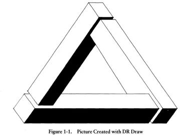
The pictures you create may be charts, diagrams, or free-form graphics. The pictures are easily reproduced on paper or transparencies for presentation. Your design and the capabilities of DR Draw combine to produce pleasing and imaginative pictures like the one shown in Figure 1-1.
I!ID DIGITAL RESEARCH®
Your Computer
CAPABILITIES
[image:17.473.33.393.56.324.2]DR Draw User's Guide
Figure 1-1. Picture Created with DR Draw
With DR Draw you can do the following:
• add a variety of design elements that include
-circles -polygons -bars -lines -arcs -text
• combine design elements to create pictures • change size and dimensions of design elements • use a palette of colors to enhance pictures • use a library of typefaces
• create word-slides with text alone
- - - I!IDDIGITAL RESEARCH®
DR Draw User's Guide Capabilities
USING THIS MANUAL
• edit your picture • save pictures on diskette
• get a presentation-quality copy of your work from a printer, plotter, or camera
• enlarge part of a picture
• expand a design beyond the confines of the display monitor
Two tutorials in this manual help you build a foundation for success with DR Draw.
The tutorials acquaint you with the basics of DR Draw and allow you to progress rapidly. Section 2 contains the first tutorial and provides step-by-step practice in basic DR Draw functions. You learn by creating charts and designs on the drawing surface. In this beginning tutorial, you also learn how to save your picture files on diskette.
Section 3 presents the advanced tutorial, which builds upon skills acquired in the beginning tutorial. It introduces to you more powerful features of DR Draw that let you create more complex designs.
Section 4 provides detailed descriptions of concepts the tutorials introduce. Section 5 provides descriptions of all DR Draw functions and Section 6 explains the DR Draw design elements.
Appendix A describes DR Draw's font library. Appendix B lists and explains error messages that can occur when you start or use DR Draw.
Use this manual with the Supplement, which tells you how to install and start DR Draw on your computer system.
Using Keyboard or Mouse
USING KEYBOARD OR MOUSE
DR Draw User's Guide
DR Draw can be used with a variety of computers. You can use either a mouse or keyboard to communicate with DR Draw.
You use two special keystrokes or mouse buttons to per-form two important DR Draw functions: PICK and DONE. PICK allows you to select a menu item or location
on the drawing surface. .
DONE completes an operation. In some cases, PICK per-forms and ends an operation without requiring DONE.
Table 1-1 shows the keys or buttons used for PICK and DONE:
Table 1-1. PICK and DONE (Keyboard/Mice)
PICK
DONE
DR Draw MENUS
Keyboard
SPACE BAR
RETURN
2-Button Mouse
e=J
[J
3-Button Mouse
CJ
CJ
DR Draw is a menu-driven program. You choose functions from a series of menus. The Main Menu provides a list of major DR Draw functions; several lead to submenus that contain more functions.
- - - I!IDDIGITAL RE.SEARCH®
DR Draw User's Guide Menu Map
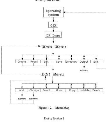
MENU MAP The menu map below routes you through the menus of-fered by DR Draw.
operating system
Main Menu
' - - - E d i t Menu
[image:20.476.62.426.90.516.2]submenu submenu
Figure 1-2. Menu Map
End of Section 1
Section 2
GETTING STARTED
INTRODUCTION
START DR Draw
With DR Draw you can easily create many kinds of charts, diagrams, and other graphic designs. This section helps you teach yourself to use DR Draw.
By following the steps in this tutorial, you quickly become familiar with DR Draw's capabilities and learn to create your own pictures.
In this tutorial you create two sample drawings: an organi-zational chart, and a design suitable for a report cover.
You must set up your computer and start DR Draw before you begin the tutorial.
Your method of starting DR Draw depends on the type of computer system you use. Refer to the Supplement for in-formation on starting DR Draw.
You need two diskettes to operate DR Draw: the work diskette that contains DR Draw and a formatted diskette on which to store your picture files. Refer to the
Supple-ment for information on formatting diskettes.
Create a Chart
CREATE A CHART
TINA GANZ
CONSULTANT
MAIN MENU
DR Draw User's Guide
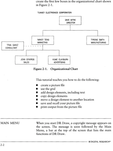
An organizational chart communicates the hierarchy of a business. In the first part of this tutorial, you learn how to create the first few boxes in the organizational chart shown in Figure 2-1.
TUNNEY ElECTRONICS CORPORATION
[image:23.473.40.421.94.600.2]HUME CLAYBURN ADVERTISING
Figure 2-1. Organizational Chart
TYRONE SMITH MANUFACTURING
This tutorial teaches you how to do the following:
• create a picture file • use the grid
• add design elements, including text • copy design elements
• move a design element to another location • save and recall your picture file
• print output from the picture file
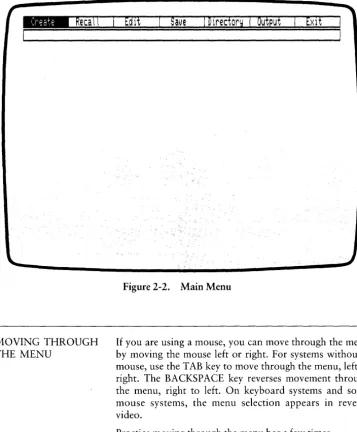
When you start DR Draw, a copyright ~essage appears on the screen. The message is soon followed by the Main Menu, a bar at the top of the screen that lists the main functions of DR Draw.
DR Draw User's Guide
_
Reca\\
MOVING THROUGH THE MENU
Main Menu
[image:24.475.68.425.59.491.2]Edit
Save
I Directory I Output
Figure 2-2. Main Menu
If you are using a mouse, you can move through the menu by moving the mouse left or right. For systems without a mouse, use the TAB key to move through the menu, left to right. The BACKSPACE key reverses movement through the menu, right to left. On keyboard systems and some mouse systems, the menu selection appears in reverse video.
Practice moving through the menu bar a few times.
PICK
PICK
CREATE A PI CTURE FILE
DR Draw User's Guide
Now begin a picture by using PICK to select a menu item.
If you are using a mouse, press the button on the far left to PICK. On the keyboard, press the SPACE BAR to PICK. To avoid confusion, the action is referred to simply as PICK throughout this guide.
From the Main Menu, PICK the CREATE function to cre-ate a picture file.
When you PICK the CREATE function, DR Draw prompts you to name the picture file:
Picture filenaMe?
When you type a filename, you must tell DR Draw which drive contains your picture diskette. DR Draw stores the picture file on that diskette. For example, if your picture diskette is in drive B, you type the drive identifier
f3:
before the filename.
In response to the picture filename prompt, type the correct drive identifier and the filename:
f3:CHI1RT
If you misspell the filename, use the BACKSPACE key to erase the mistake, and retype the name. Press the RETURN key.
For the filename you can use any combination of letters or numbers that does not exceed eight characters. DR Draw ignores characters after the eighth character. Also, do not use punctuation marks or spaces.
- - - I!ID DIGITAL RESEARCH®
DR Draw User's Guide
_
Change
Create a Picture File
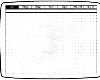
The Main Menu disappears and a rectangle appears, rapid-ly filling with a grid of points. The rectangle is the window frame. It encloses the drawing surface where you work. A new menu bar replaces the Main Menu. This is called the Edit Menu, and it lists the functions you can use to make your organizational chart. The grid of points acts like elec-tronic graph paper to help you align different design ele-ments.
[image:26.475.72.420.166.445.2]Select
Move COPYI Un de tete I De tete
Figure 2-3. Edit Menu, Grid, and Window Frame
Draw Elements DR Draw User's Guide
DRAW ELEMENTS To draw the organizational chart, you add different design elements to the grid one by one, much in the way a graphic artist builds a design with overlays. A design element is any shape, symbol, or unit of text that you use in the picture. You begin by using lines to draw boxes.
RETURN AND DONE If you PICK the wrong menu item here or anywhere in the tutorial, press the DONE key to return to the previous menu, and PICK again. On keyboard systems, you press the RETURN key for DONE. On a mouse, the second button from the left signals DONE.
DRAW LINES
If you press the DONE key when you are in the Edit Menu, your picture disappears from the screen, and the Main Menu appears. To return to the Edit Menu and continue working on your picture, PICK the EDIT function from the Main Menu.
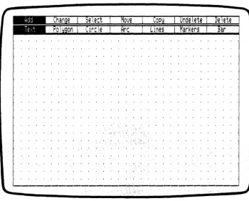
PICK the ADD function from the Edit Menu. A new menu of shapes and figures appears below the Edit Menu. These are the design elements you use to create your picture. Refer to Section 6 for descriptions of DR Draw's design elements.
- - - [!]]DIGITAL RESEARCH®
DR Draw User's Guide Draw Lines
Figure 2-4. Edit Menu and Add Submenu
PICK the LINES design element from the Add Submenu. A cross hair (+), called the graphics cursor, appears at the center of the drawing surface. The center of the cursor marks your position on the drawing surface. The graphics cursor appears when you PICK a menu item that adds a design element or changes a picture element. The cursor also appears when you need to PICK a point for reposition-ing elements or changreposition-ing your view of the drawreposition-ing surface. For details on the graphics cursor, refer to Section 4.
Draw Lines DR Draw User's Guide
On the second menu line, DR Draw tells you
PICK pointst press DONE when finished
You begin creating the organizational chart by drawing lines. You PICK starting and ending points. DR Draw joins the two points to form a line. You can add additional line segments by adding successive points to the element.
If you are using a mouse, move it, and the graphics cursor moves correspondingly. On a keyboard system, use the arrow keys to move the cursor. If you are using arrow keys, note that each press of an arrow key moves the cursor part of the distance between grid points. For example, you might press the cursor key five times to move 4 grid points across the drawing surface.
To begin drawing the chart, locate your cursor at the cen-ter grid point on the drawing surface. Move the cursor straight up 3 grid points and PICK. This is your starting point. No line appears, but you might have noticed that the cursor attaches to the nearest grid point if you were not directly over a grid point. This is the SNAP feature, which helps you align design elements by "snapping" the cursor to the nearest grid point on the drawing surface. The SNAP feature is useful for aligning design elements in a picture.
Move the cursor left 4 grid points. On most systems, a line follows the cursor. This is DR Draw's rubberband line, which allows you to see how the line looks before you PICK an endpoint.
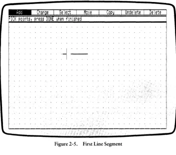
PICK the point. The dashed line becomes a solid line be-tween the two points you PICKed-the beginning of a box. See Figure 2-5, "First Line Segment."
DR Draw User's Guide Draw Lines
[image:30.471.68.420.62.370.2]MOlJe Undelete De I,ete
Figure 2-5. First Line Segment
Now move the cursor up 3 grid points on the grid and PICK again. Another solid line appears.
You can move the cursor over the drawing surface freely. Line segments join only the points that you PICK.
IIID DIGITAL RESEARCH@
Draw Lines
'.
~.
DR Draw User's Guide
Move the cursor 8 grid points to the right and PICK once more. Another line appears. Your box is more than half complete.
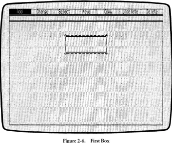
Move the cursor 3 grid points down and PICK. One more line segment completes the box. Move the cursor 4 grid points to the left to the point where you began and PICK. The final line closes the box. Now press the DONE key to tell DR Draw that the element is complete. You have cre-ated your first design element with DR Draw.
Undelete
r
De
tete
, .
't- ----
~- ..;~-~I" ,.," ",', ""'" " l ' " I.' _ I , I _ ~ J -, _. _ I
1
,. ___ -u-, __ -"
[image:31.471.47.401.184.476.2]."; ' , , - - -''-,
Figure 2-6. First Box
The Add Submenu and the graphics cursor disappear. A broken line, enclosing the box you just drew, appears on the drawing surface.
- - - I!IDDIGITAL RESEARCH®
DR Draw User's Guide
DELETE AND UNDELETE
Draw Lines
The broken line is the extent. It marks the current element. The current element is the only design element you can change. Ordinarily the current element is the most recent design element you worked on. However, when you save a picture file on diskette and recall the file, the first element you added to the picture becomes the current element.
The advanced tutorial in Section 3 explains how to use the SELECT function to name a new current element.
If you made a mistake and want to redraw the box, you can delete the design element with DR Draw's DELETE function. DELETE removes the current element from the drawing surface.
If you accidentally delete an element, the UNDELETE function redraws the last element you deleted, regardless of the number of operations you performed since the deletion.
Practice DELETE and UNDELETE. PICK the DELETE function from the Edit Menu. DR Draw erases the box.
Notice that the grid points below the deleted box also disappear. You can restore the grid points by using the REDRAW function. PICK the CHANGE function from the Edit Menu. From the Change Submenu, PICK the REDRAW function. DR Draw erases the grid, then re-draws the grid to restore the missing grid points.
PICK the UNDELETE function. DR Draw redraws the box you deleted on the drawing surface. The extent reappears, defining the box as the current element.
Copy Elements
COPY ELEMENTS
DR Draw User's Guide
To proceed with the organizational chart, you want to draw several more rectangles. You do not have to redraw each box with the LINES design element. Instead, use another DR Draw function, COPY.
PICK the COpy function from the Edit Menu. The graphics cursor reappears. DR Draw prompts
PICK reference point
Move the cursor to the upper left corner of the current ele-ment. By positioning the cursor on or near the extent corner, you can more easily locate new elements. PICK the point.
_ .
Undel.ete ·1 · Delete
' .. J ' ; ' " , , , ,
, : 1.\ .... ·.--.' ... -..-.'.'--. -.
Uj
, , ·1 ... ".' , ". ' . ' .
, , ; ; ' . . . II
?'t~" ~ - - - ~
...
----_
...
-_
...__
...---
... - . . ....- - - -
...
- ...-Figure 2-7. Cursor Position (COpy)
- - - I!IDDIGITAL RESEARCH®
DR Draw User's Guide Copy Elements
A new prompt appears.
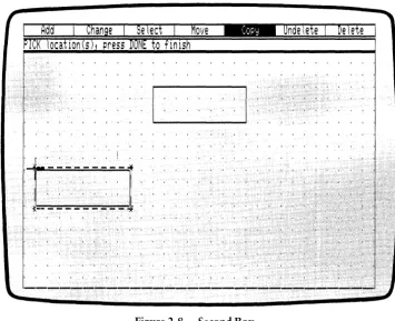
PICK locatiords), press DONE to finish
Move the cursor 7 grid points down, then 10 grid points left. PICK again. A duplicate of your first box appears below and to the left of the original. The extent now sur-rounds the new box, which is the current element. The
prompt remains on the screen. .
_
Onde I,ete
I
De tete
1-.:...:-..:.:....:-!-~
, " " ' " I
'I, ' , , , , , ,
I
, :C .. - - - - - -
!
Figure 2-8. Second Box
COpy allows you to make as many copies as you wish in the same operation, as long as the total number of elements in the picture does not exceed 200.
I!ID DIGITAL RESEARCH®
[image:34.473.69.424.168.457.2]Copy Elements
MOVE ELEMENTS
DR Draw User's Guide
Now add another box to the chart. Using the upper left corner of the new box as the starting point, move the cursor 21 grid points to the right and PICK once more. Another copy of the box appears, surrounded by the ex-tent.
Press the DONE key to finish copying. DR Draw returns you to the Edit Menu.
The last box you added to the picture is slightly off center. DR Draw's MOVE function makes it easy to realign your chart.
The MOVE function allows you to move the current ele-ment anywhere on the drawing surface.
PICK the MOVE function from the Edit Menu. DR Draw prompts
PICK reference point
Move the cursor to the upper left corner of the extent. PICK the point. A prompt appears.
PICK new locationt press DONE to finish
Move the cursor 1 grid point to the left and PICK. The box shifts to the new position. You are still in the MOVE func-tion, so you could move the box again if necessary. Press the DONE key to return to the Edit Menu.
- - - I!ID DIGITAL RESEARCH@
DR Draw User's Guide
CHANGE GRID SIZE
Move Elements
Select
Move
COPY
Undelete I De\ete
11 - - - --~
~
" " I
~
-
~ ~ ~
-
'-
~ ~
-
'--~
Figure 2-9. Third Box
Before you add text to the boxes you should substitute a denser grid for the present grid. Adding more grid points to the drawing surface lets you more easily position text with-in the boxes. The GRID function allows you to change grid density.
From the Edit Menu, PICK the CHANGE function. The Change Submenu appears under the Edit Menu. PICK the GRID function. The Grid Submenu replaces the Change Submenu. PICK the SIZE O.SX function. The grid dis-appears, line by line, and a new, denser grid appears on the drawing surface. The new grid is twice as dense as the original grid. The Grid Submenu disappears.
IIID DIGITAL RESEARCH®
Add Text
ADD TEXT
DR Draw User's Guide
The trio of boxes is a start, but you need to add labels to them. Like shapes, you add text with the ADD function.
PICK the ADD function from the Edit Menu. When the Add Submenu appears, PICK the TEXT design element. DR Draw prompts
PICK startt typet RETURN; DONE finishes
If you are using the arrow keys to move the cursor, you can more easily locate grid points by slowing the cursor. A designated key on your keyboard changes the cursor's speed. Refer to the Supplement to identify the key.
You change the cursor speed by pressing the key to in-crease or dein-crease speed. When you identify the cursor speed key, practice moving the cursor around the drawing surface and alternating between fast and slow speed.
When you feel comfortable with changing cursor speed, you can add text to the first box you created by completing the following instructions.
Within the top box, move the cursor 3 grid points up from the box's lower left corner, then move the cursor 4 grid points to the right. PICK the point. The graphics cursor disappears. An underscore, the text cursor, replaces the graphics cursor.
- - - I!IDDIGITAL RESEARCH®
DR Draw User's Guide Add Text
COPy
Undelete I Delete
.:::::.::::::.::::::.:
[,
:-:
.••
:"::::]::::::
••
:::::
••
::.::::
Figure 2-10. Text Cursor
Add Text DR Draw User's Guide
Type the following:
DAVE MITRE
If you make a typing error, use the BACKSPACE key and retype the box label.
After you type the text string, press the RETURN key. The graphics cursor appears below the letter D.
Press the DONE key to finish entering text. The extent appears around the text you just typed.
For detailed information on entering text, refer to Section 6.
_
Chan~eI Setedl Move
COPY
I Undelete I Delete I
I ~ , • I j , • I I , I I 0" t I , , " I , I I . ' • I, I I I f " I' { .. " I I " , • I • . ' 1 • I • " " t • , • j ' , I I I ' , , I , • , I
:.: : : : : : : : : : :.: : :. : : : : : : :
·r:-,-1:-;~-";~~1-:-:-~: : : :.: : : : : : : : : : : : : : : : : :
" , , , , , , , , , , , , , , . , , , , , I ' ,
'IDAVE M
ITRq . , ,
I ' , , , , , " , , , , , , , , , , , , , ,
:~ ~;;
;
~::
; ; :; ; : : : : : :. : :
L~~~~~=:~=~~~~~J
;: ;; :
~
; :: : : :: ;;: : :: ;; :
I . ' 1 ' 1 t " t ' I ' • I t , t • I I I • I . , , • I ' " " • I , " 1 1 I I I 1 " ' 1 ' 1 I I . , I " I • • • • 1 ' 1 I I I 1 ' 1 ' • • , ' I ' , . " , . , • I . I I " . ' • I I I I . I I I I I , 0" I " I I I ' , , . " •
Figure 2-11. Box Label
- - - I!Q]DIGITAL RESEARCH@
DR Draw User's Guide
CHANGE TEXT STYLE
ADD MORE TEXT
Change Text Style
The style of text DR Draw used for your text entry is known as machine font. This is the initial style that DR Draw uses for all text until you specify otherwise. The size and shape of machine font characters may vary between different computers and output devices, so you want to change the font style to one of the typefaces included with DR Draw. These fonts remain the same on screen, plotter, and printer outputs.
PICK the CHANGE function from the Edit Menu. When the Change Submenu appears, PICK the STYLE function. A submenu of font options appears. PICK the Simplex submenu selection. The font Simplex Roman replaces the initial style in the box label.
Now add a title to the name you entered in the first box. PICK the ADD function from the Edit Menu. From the Add Submenu, PICK the TEXT design element. DR Draw prompts
PICK start, type, RETURN; DONE finishes
Use the lower left corner of the first box as a starting point. Move the cursor up 1 grid point and 5 grid points to the right of the box's lower left corner.
Add More Text DR Draw User's Guide
: :::::
~::
:::: ::. :::
:::~: F:~:~-,~:~:~'-:-'-~'-:-:~-:l:'::
; ::::;:: : : ::':::::
, " , , , . . " , , . . . , . . " I ' , .'
,DrVS: .Mrt.RE:. , . ',I" • .,' " . • . • , • ',' • , , . ,,' , '..: : :: : : :: : :: : : :: :: : : : ::
.~~~~:f:.:~~~~~~-:~J::
, '::
:<::<:::~
::
i:(:
r I , c".', \ ' , '0 , \ i f ' ,,~ I i , 'j I , , • • , ' " . ' I , t • • • ; , t I • I " I • , ' f I I " f I , I I I I , " ' • , I , , , I ' , , , I • • , • , I I • I • • " , I ; I t I · I " I, ~ f • , , , I I I I , I , , , • ' . I' , . ' , , • , , , .• , t • I
I " . , I " • • , I • • ', " ' , , 1 r . , • 1 , 1 I I, I , J " , I _ . i , ' J i • I I " ' . " " " , , " 1 I " , " • • , •• , I ',I,' I I
, I I I I I ' • , . , ' , r " J " ,
I I ' , , , , • • • • , I , . , . I I 1 1 I. I I • " " , • • '.1' I , i , ' I " , I ' • • • • , " I , , " , , . , , ' I . I I I I I . I " . , ' , . " , • " " , ' ,
• , " • I , , I • I , , • , ~. • I , I • " • • , , I , t • I I I , , \ ' . • / 1 , I ' I I , I • • I I , , • • , 1 " I I I I I I " I , j I , ' , " , . , ' , • I , ' " I I ' I h ' , . I ) I ; ' . , I I I , , , • , • • , , , . ' 1 , , " " , , , '. , , , , , ' j • I ' I I , ' • I , I t i l ' j I " ' , I i . , ~
Figure 2-12. Cursor Position (TEXT)
PICK this point. The text cursor replaces the graphics cur-sor. Type the following:
DIRECTOR
The words appear in the machine font as you type. A bouncing extent surrounds the text to show you the size of the element as it will appear in the current font style, Sim-plex Roman. Press the RETURN key. The font style changes to Simplex Roman, and the cursor moves to the next line.
- - - I!IDDIGITAL RESEARCH®
DR Draw User's Guide Add More Text
When you press the RETURN key after typing a string of text, you can use the mouse or arrow keys to move any-where on the drawing surface, PICK a point, and type another text string. This feature enables you to add the remaining box labels in one operation.
Using the labels in Figure 2-13, add text to the remaining boxes. Type the names on the third row of grid points above the boxes' lower edges. Type the titles on the first grid row above the lower edges. Do not worry if the text is not centered perfectly the first time you add the labels. Press the DONE key when you are finished.
_
Change I Se ted I Move
COPYI Unde tete I De tete I
:::::::::::::::::::::: r,-,-,-,-,-,-,-,-,-,-,-·-,-,-,i::::::::::::::::::::::
. . , , , , . , , , , , , , , , , , , , , . I • , , CAVE MITFI!E: . , , I • , , • , • • , • , • , , • , , , , • , • •
~
; : ; ;: : ; ; ; ;: ; : ; ; : : : : : ;
L~~~~E~~:~!
__
~:_J
: ::: : : ; : : : ; : :: : : : : : :: :
, " , , , " , . , , I I , I ' , " " I I " , . ' ' " . , • • • ' , . t . ' I I I 1 1 ' , , ' , . " . , , • • I "
: : r.-:-,-:-.-:-.-:-.-:-,-:-.-:-.I : : : : : : :.:.:.: : : : : : : : : ::.: : : r.-:-.-:-,-:-,-:-,-:-.-:-,-:-.I :.:
, , I . , ,
NANCY TENG' "I . , , , , , '.' , , , . , , , , . , ' .. ' ; , . t··
TY~a~~E SMITH ,.I .,
: : I : : :
'~11A~KtrINQ
<:
I : : : : : : : : : : :: : : :: :: : :: :
:1:J~NUFAcruRiN-;"*:
I: :
, . L..;...::.. ____.-.:._...l , , . .., , , . . . , , , . . , , . . ,
,L -::.:-=-=-=--:l.:...l ..
, I , '" , I I I I I J , ' r l . , , " " I , • • • • • , ' 1 ' 1 I I • • • , • ( , I I I I I ' , I I , , " • " , I I .
, • , • , , , • , I ,~. I , I I I I I • , , , , , , , I I I t I I , , , • I • • I' , • • t ~, , I , , I t I I t ' , • • I ,
, " • • , . , t I , , I I I I 1 " \ " " I " , . I t t . , I ' • " I , J . I I , . , 1 , I I I 1 ' 1 " . , •
Figure 2-13. Labeled Boxes
Change Grid
CHANGE GRID
ADD LINES
DR Draw User's Guide
Before you join the labeled boxes with lines, change the grid density. A sparser grid of dots lets you more easily count grid points for centering lines.
From the Edit Menu, PICK the CHANGE function. When the Change Submenu appears, PICK the GRID function. The Grid Submenu replaces the Change Submenu. PICK the SIZE 2X function. The grid disappears, line by line, and a new, less dense grid appears on the drawing surface. The new grid is half as dense as the previous grid.
To complete the chart, you need to join the rectangles with lines.
PICK the ADD function from the Edit Menu. When the Add Submenu appears, PICK the LINES design element.
DRDraw tells you
PICK pointst press DONE when finished
Use PICK to draw line segments between the boxes. Start-ing from the lower right corner of the top box, move the cursor 4 grid points to the left. Because the cursor snaps to the nearest grid point when you PICK, move the cursor close to the center grid point on the box's lower edge. See Figure 2-14. PICK the point. The cursor snaps to the nearest grid point.
- - - I!ID DIGITAL RESEARCH®
DR Draw User's Guide
_
Change
I
Se
teet
Move
COPY
PI\~K
pomts, press
DONEwhen flnlshed
,---,
I '
'DAVE MTR E' ,I
L_'.!~O~~.J
I , , • , ' , , •
Add Lines
Undelete
I
Delete
Figure 2-14. Cursor Position (Adding Lines)
Add Lines DR Draw User's Guide
Move the cursor down 2 grid points and PICK. A line appears between the two points. Now you want to create two line segments that branch out to the remaining boxes. Move the cursor 10 grid points to the right. PICK the point.
Now move the cursor down 2 grid points and PICK. A line joins the two boxes. See Figure 2-15.
I--~-'---~--I·
I '
NANC:rT~NGI1~_~RK£:rIN'::_~
Figure 2-15. Boxes Joined with Line
- - - i!IDDIGITAL RESEARCH@
DR Draw User's Guide
SAVE A PICTURE
Add Lines
You now want to join the box on the left to the rest of the diagram. You can do this by pressing the DONE key and PICKing the LINES design element again from the Add Submenu, or you can retrace your steps by completing the following instructions.
Move the cursor back up 2 grid points and PICK again.
Your figure looks the same because you have drawn a line on top of another line. Move the cursor 20 grid points to the left. PICK the point.
As you move the cursor, the right side of your line may disappear. The rubberband line following the cursor cre-ates this effect. Your line is still there.
To draw the final line, move the cursor down 2 grid points and PICK.
Press the DONE key to complete the line element. Notice that the extent traces a rectangle around the entire line element.
You have drawn a simple organizational chart with DR Draw. The advanced tutorial in Section 3 teaches you how to expand this chart into the organizational chart shown in Figure 2-1.
Now that your chart is complete, you can save it on disk-ette for future reference.
Press the DONE key. The organizational chart, window frame, and grid disappear. The Main Menu replaces the Edit Menu at the top of your screen.
PICK the SAVE function. DR Draw prompts
B:CHART? (or type new naMe)
[!]) DIGITAL RESEARCH®
Save a Picture
CHECK DIRECTORY
RECALL PICTURE FILE
DR Draw User's Guide
DR Draw is gIvmg you the opportunity to change the filename. Changing a filename is discussed in "Rename Picture File" later in this tutorial. You can also change the drive identifier if you want to store the picture file in a different drive. Refer to "Create A Picture File" at the beginning of this section for an explanation of drive iden-tifiers.
To keep the same picture filename and drive identifier, press the RETURN key. DR Draw replies
B:CHART: savin~ file
N ow check your directory of picture files to ensure CHART has been saved on the diskette.
To list the picture files on diskette, PICK the DIRECTORY function from the Main Menu. DR Draw prompts
On IAlhich drive?
Type the letter of the drive that contains your picture diskette and press the RETURN key. DR Draw lists the picture files on the diskette. Check to see if the picture file CHART is listed. DR Draw returns you to the Main Menu. The directory remains on the screen until you PICK another function and it uses the drawing surface.
To retrieve your picture file to display or modify it, use the RECALL function. In this case you will be preparing the picture file for printing.
PICK the RECALL function from the Main Menu. DR Draw prompts
B:CHART? (or type new name)
Press the RETURN key. DR Draw prompts
B:CHART: readin~ file
- - - I!IDDIGITAL RESEARCH®
DR Draw User's Guide
LAYOUT
_
Change
Recall Picture File
DR Draw draws your chart on the screen and displays the Edit Menu. The first element created, a box, is now the current element.
Before you print the picture file, use the LAYOUT function to format your picture file. DR Draw only prints the por-tion of a picture file that lies within the layout. Elements outside the layout are not printed even though they are part of the picture file.
DR Draw gives you a choice of three layouts: PORTRAIT, LANDSCAPE, and SCREEN. The examples in Figures 2-16a through 2-16c illustrate the three different layouts.
Se led
Move
COPY
I undetete I Delete
...
---
...
---
...
--~...
----
...
--Figure 2-16a. LANDSCAPE Layout
LAYOUT DR Draw User's Guide
Figul'e 2-16b. SCREEN Layout
DR Draw User's Guide LAYOUT
_
Change
Select
Move
COPY
Undelete I Delete
• t • • •
Figure 2-16c. PORTRAIT Layout
SCREEN is the default layout, the format that DR Draw uses if you do not select a layout.
Now look at how LAYOUT can affect the picture file. PICK the CHANGE function from the Edit Menu. When the Change Submenu appears, PICK the LAYOUT func-tion. The Layout Submenu appears. PICK the PORTRAIT layout. DR Draw adds a solid-line rectangle to the grid. You can see that part of the chart lies outside the POR-TRAIT layout.
LAYOUT
ZOOM FULL
DR Draw User's Guide
Now try the LANDSCAPE layout. PICK the CHANGE function from the Edit Menu. When the Change Submenu appears, PICK the LAYOUT function. PICK the LAND-SCAPE layout from the Layout Submenu. DR Draw re-places the PORTRAIT layout with the LANDSCAPE lay-out. Note that in this case LANDSCAPE, like PORTRAIT, does not frame all the elements in the organizational chart.
Refer to Section 5 for more details on the LAYOUT func-tion.
You can fit the organizational chart into the LANDSCAPE layout by using DR Draw's ZOOM FULL function. ZOOM FULL reduces or enlarges the picture file to fit the current layout.
From the Edit Menu, PICK the CHANGE function. When the Change Submenu appears, PICK the VIEW function. The View Submenu appears on the screen. PICK the ZOOM FULL function. DR Draw proportionally reduces the contents of the picture file to fit the LANDSCAPE lay-out.
- - - IIIDDIGITAL RESEARCH®
DR Draw User's Guide ZOOM FULL
_
Change
Select
Move
COPYI Unde tete I De tete
r=-:':~M~';~
-1
II
·_·~1"~~..':.·_·
II : : : : : :I , I I , ' I I • , , I I I
r--:-- - -] - - -
~. r--- ---,
.
.'--'-'
. .
. . ..
. . . .. .
.
.
.. ..
. . . .
-:-;;~~
r.N;!
r~;;;;;;-l
~....:~~~
.
....:J
L~~~AUrvRI.~.J
Figure 2-17. Organizational Chart in LANDSCAPE Layout
RENAME PICTURE FILE
You can only print a picture file when it is saved on disk-ette. Press the DONE key to return to the Main Menu. PICK the SAVE function from the Main Menu. DR Draw prompts
B:CHART? (or type new naMe)
Il]] DIGITAL RESEARCH®
Rename Picture File
PRINT PICTURE
DR Draw User's Guide
Because you need to keep the original CHART for the advanced tutorial in Section 3, you must rename this ver-sion of the picture file. To rename the picture file, type
B:CHART2
in response to the prompt, and press the RETURN key. DR Draw displays this message:
5:CHART2: sauin~ file
When the message disappears, DR Draw has saved the new picture file on diskette.
You now have two versions of the organizational chart on your picture diskette. CHART is your original version in SCREEN layout. CHAR T2 contains the same design ele-ments, but the file is in LANDSCAPE layout.
If you had pressed the RETURN key without typing a new filename, DR Draw would have replaced the version of CHART saved on your diskette with the version on which you have been working.
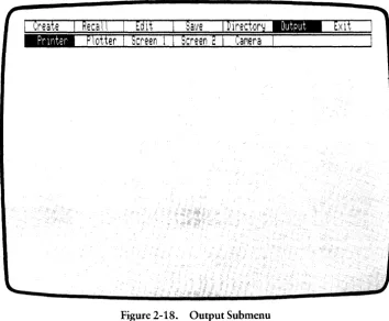
Use the OUTPUT function to print the picture file CHART2.
PICK the OUTPUT function from the Main Menu. DR Draw displays a new menu that offers a choice of output devices.
- - - [!IDOIGITAL RESEARCH®
DR Draw User's Guide Print Picture
Figure 2-18. Output Submenu
PICK PRINTER from the Output Submenu. The Output Submenu disappears and DR Draw prompts
B: CHART2? (0 r t }'pe nel ... 1 nafr\e)
Press the RETURN key.
After a pause, the picture file begins to print. When print-ing is complete, the Main Menu reappears.
Congratulations, you have completed the first sample drawing in this tutorial and learned some basic DR Draw functions in the process. The sample picture that follows introduces you to more DR Draw functions.
liID DIGITAL RESEARCH® :
Print Picture
CREATE A DESIGN
DR Draw User's Guide
If you want to take a break from the tutorial, PICK the EXIT function from the Main Menu to return to the oper-ating system. The operoper-ating system prompt appears, which signals your departure from DR Draw. To restart DR Draw, follow the instructions in the Supplement.
[image:55.474.43.414.35.611.2]In addition to creating charts and other diagrams, DR Draw allows you to create designs or pictures. In this part of the beginning tutorial, you use DR Draw to create a pencil design.
Figure 2-19. Pencil Design
If you took a break from the tutorial and exited DR Draw, restart DR Draw. If you do not remember how to do this, refer to the Supplement.
- - - I!IDDIGITAL RESEARCH@
DR Draw User's Guide
CREATE A PI CTURE FILE
Create a Picture File
To begin, create a picture file in the same way you created CHART.
From the Main Menu, PICK the CREATE function. DR Draw prompts you for a filename:
Picture filenaMe?
Type the following, then press the RETURN key:
B:PENCIL
The rectangular window frame returns to the drawing sur-face. The Edit Menu replaces the Main Menu. You are ready to draw.
Draw Circle
DRAW CIRCLE
DR Draw User's Guide
Start by drawing a circle. PICK the ADD function from the Edit Menu. The Add Submenu appears below the Edit Menu. PICK the CIRCLE design element. The graphics cursor (
+ )
appears at the center of the drawing surface and DR Draw promptsPICK circle center
Position the cursor on the center grid point on the drawing surface and PICK. An asterisk marks the point. DR Draw now prompts
PICK circle radius
You are ready to tell DR Draw how large the circle will be. Move the cursor 6 grid points to the left and PICK. Another asterisk marks the point.
The graphics cursor disappears and a new submenu offers you the choice of creating an OPEN circle or a FILLED circle. An OPEN circle is a circular line. A FILLED circle is a circular line with one of several fill patterns inside.
PICK the OPEN circle. After a pause, the circle appears on the drawing surface, surrounded by the extent.
- - - I!IDDIGITAL RESEARCH®
DR Draw User's Guide
_ Change I Se ted Move
COPY
~ _ _ _ _ _ _ _ ~~ _ _ _ _ _ _ _ .Ii
I I , " - - - • I , , IIIi
, " " . . , ,··1
I, . / . . , . " . " ,
, 1(:1 •
.:
1 ' , I '
,1.\, : .. , .. ' , . ,
'/'1
I·'~"'.'."·'"
, , , . , , , . , , , , ·1I' " " ' " ' "
~ , , , , . , , , I
[image:58.474.71.423.58.345.2]~---~~~~--~-~
Figure 2-20. Circle and Extent
Draw Circle
undelete I Delete
I!IDDIGITAL RESEARCH®
Add Polygon
ADD POLYGON
DR Draw User's Guide
Now add another element to the design. The POLYGON design element allows you to create a filled element with as many sides as you want. In this picture, you will be draw-ing a triangle.
From the Edit Menu, PICK the ADD function again. When the Add Submenu reappears, PICK the POLYGON design element.
The graphics cursor appears and DR Draw prompts
PICK pointst press DONE when finished
Starting from the center point of the circle you just created, move the cursor 14 grid points to the left and PICK. You have now marked a corner of the triangle. Now move the cursor up 1 grid point and 3 grid points to the right. PICK the second point. The first side of the triangle appears on the screen.
To draw the second side of the triangle, move the cursor down 2 grid points and PICK.
To rejoin the starting point, move the cursor 3 grid points to the left and 1 grid point up. PICK the point. Press the DONE key.
The cursor disappears, and the triangle turns solid. This solid fill is known as the initial style. If you do not specify another fill pattern, DR Draw assumes you want the solid fill. Notice that your screen shows the solid area in light shading. When you print or plot the picture, this area is black or solid colored. You will learn how to add or change colors in the "Color" subsection of this tutorial. For more information on the STYLE function, refer to Section 5.
DR Draw User's Guide Add Polygon
_
Change
Setect
Move
COPYI Onde
tete
I
De lete
'~"""
• • " • • I I .
, , , , , , , , , ,'\,
.
:~
, . , J
')"
, , , , ,/,,
-Figure 2-21. First Polygon
[!ill DIGITAL RESEARCH®
[image:60.475.73.424.60.367.2]Add Another Polygon
ADD ANOTHER POLYGON
STYLE
DR Draw User's Guide
Now, use the POLYGON design element to add another element to the picture.
PICK the ADD function from the Edit Menu. When the Add Submenu appears, PICK the POLYGON design ele-ment.
The cursor reappears and DR Draw prompts
PICK pointst press DONE when finished
To locate a starting point, move the cursor to the upper right corner of the triangle you just created. PICK the point.
Move the cursor up 1 grid point and 3 grid points to the right. PICK the point to draw the first side of the polygon.
Move the cursor down 4 grid points and PICK again.
Draw the third side of the design element by moving the cursor 3 grid points to the left and up 1 grid point. PICK the point.
Complete the polygon by moving the cursor up 2 grid points. PICK the point. Press the DONE key. The solid fill appears in the polygon. The cursor disappears, and the extent encloses the polygon.
To change the fill pattern of the polygon, use the STYLE function.
PICK the CHANGE function from the Edit Menu. When the Change Submenu appears, PICK the STYLE function. A menu of different fill patterns appears.
PICK the first fill pattern. The solid fill disappears, leaving the outline of the polygon. The new fill is the hollow fill. Although the element looks empty, the hollow fill masks any element underneath it. Refer to Section 4 for details on hollow fill.
- - - i!IDDIGITAL RESEARCH®
DR Draw User's Guide
_
Change 1 Setect
Move .1COPY
<1
I • I I ' ,---I
, , , I , , ~--
-
...
,:/-,~,:
'I' , "
" " '\ '
,/ ' , " "" »:
I ' , , , , , , , , , ,
\:
:
:
:
:
:
:
:
:
: :
:~':::::.::.::/
:::':::::
'/:
[image:62.474.69.421.66.360.2]I I • , , • I I I 1
Figure 2-22. Second Polygon
STYLE
Undetete 1 Detete
IIID DIGITAL RESEARCH®
Bars
BARS
DR Draw User's Guide
Now use the BAR design element to draw the body of the pencil. With the BAR design element, you can draw rec-tangles in all sizes, ranging from long, thin bars to squares. From the Edit Menu, PICK the ADD function. From the Add Submenu, PICK the BAR design element. DR Draw prompts
PICK corner of bar
You define the bar by choosing corners that are diagonally opposite each other.
Move the cursor to the lower right corner of the hollow-filled polygon and PICK. An asterisk marks the point. DR Draw prompts
PICK opposite corner of bar
Move the cursor up 4 grid points, then 16 grid points to the right. PICK the point. A hollow bar appears, and the extent encloses the new element.
Now change the new element's fill to a solid fill. PICK the CHANGE function from the Edit Menu. When the Change Submenu appears, PICK the STYLE function. From the menu of fill patterns, PICK the second style. The solid fill replaces the hollow fill in the bar.
- - - I!IDDIGITAL RESEARCH®
DR Draw User's Guide
_
Change
Bars
[image:64.471.71.422.64.364.2]Select
Move
COPyI Uncle tete I De lete
Figure 2-23. Bar
You have now created three different elements and.are well on your way to completing the picture.
COLOR (Optional)
COLOR (OPTIONAL)
DR Draw User's Guide
The DR Draw COLOR function allows you to add color to your design elements. If your computer or output devices have color capabilities, you will want to experiment with the COLOR function. Skip this section if neither your com-puter nor output devices have color capability.
To see the Color Submenu, PICK the CHANGE function from the Edit Menu. From the Change Submenu, PICK the COLOR function.
The Color Submenu contains eight rectangles numbered 0 through 7. On some color monitors the rectangles also contain the color represented by the number.
Printers and plotters do not necessarily have as many col-ors or the same colcol-ors as the monitor. For example, your monitor might have four colors, and your printer might only have three. In addition, color number 2 on your moni-tor might be blue, but on your printer it might be magenta.
To learn which colors you have on your monitor and prin-ter or plotprin-ter, you can make a sample color file, as de-scribed in the description of the COLOR function in Section 5.
If you are working with a monochrome monitor, design elements remain monochrome on the display screen, but you can still print or plot in color.
DR Draw User's Guide
CHANGING COLOR
[image:66.475.69.423.59.351.2]COLOR (Optional)
Figure 2-24. Color Submenu
To change the color of the BAR design element, PICK color number 3 from the submenu. The Color Submenu dis-appears. If you are working in color on the screen, the bar changes its color to the hue corresponding to number 3 in the menu.
Arcs
ARCS
DR Draw User's Guide
Use the ARC design element to finish creating the pencil. An arc is either part of the circumference of a circle, or it is a filled pie section. For more information on arcs, see the description of the ARC design element in Section 6.
T a add an arc to the design, PICK the ADD function from the Edit Menu, then PICK the ARC design element from the Add Submenu. DR Draw prompts
PICK arc cente r
Move the cursor down 2 grid points from the upper right corner of the bar, then 1 grid point to the right.
PICK the point. An asterisk marks the arc center. DR Draw prompts
PICK arc radius/beg'inning' of arc
Move the cursor down 2 grid points and PICK. Another asterisk appears and DR Draw prompts
PICK end of arc
Move the cursor up 4 grid points and PICK the point. Before the arc appears, DR Draw asks you if you want the arc OPEN or FILLED. PICK a FILLED arc. After a pause, the arc appears. The arc completes the pencil figure. You have created a drawing that demonstrates some of DR Draw's many functions.
- - - i!IDDIGITAL RESEARCH®
DR Draw User's Guide
_
Change
.1
SAVE THE PICTURE
Arcs
Select
Move
COPyI Unde tete I De lete
[image:68.473.69.421.63.365.2]I
l-·--~
Figure 2-25. Arc Element
You need to save your drawing for the advanced tutorial in Section 3, where you will add some new twists to the de-sign. Press the DONE key to return to the Main Menu. The pencil drawing disappears.
From the Main Menu, PICK the SAVE function. DR Draw prompts
5:PENCIL? (or type new naMe)
If you want to save the picture file on this drive and with this name, press the RETURN key. DR Draw prompts
5:PENCIL: savin~ file