Digital Equipment Corporation
Maynard, Massachusetts
mamaama
ADVANCED SOFnNARE
SYSTEM MONITORS
For additional copies order No. DEC-9A-MADO-D from Program library,
1st Printing March 1967
2nd Printing Revised February 1968 3rd Printing Revised May 1968 4th Printing Revised January 1968
Copyright© 1968 by Digital Equipment Corporation
Instruction times, operating speeds and the like are in-cluded in this manual for reference only; they are not to be taken as specifications.
The following are registered trademarks of Digital Equipment Corporation, Maynard, Massachusetts:
DEC FLIP CHIP DIGITAL
ii
PDP FOCAL
1.1
1.2
1.3
1. 3. 1
1.3.2
1.3.3
1.4
1.5
1 .5. 1
1.5.2
1.5.31.5.4
1 .5.5 1.5.61.5.7
1 .5.81.5.9
1.5.10
1.
5. 111.5.12
2. 1 2. 1 . 1 2.1.2 2.2
2.3
2.3.1
2.3.2
2.3.3
2.3.4
CONTENTSCHAPTER 1
PDP-9 ADVANCED SOFTWARE SYSTEM
Introduction
Hardware Requi rements Monitor Systems
Input/Output Monitor Keyboard Monitor
Background/Foreground Monitor Input/Output Programming System (lOPS) System Programs
FORTRAN IV Compiler MAC RO -9 Assemb ler
Dynamic Debugging Technique (DDT) Program T ext Editor Program
Peripheral Interchange Program (PIP) Linking Loader
PDP-7 to MACRO-9 Assembly Language Converter System Generator
Dump Program
Library Update Program System Patch Program
Chain Builder and Execute Programs
CHAPTER 2
THE PDP-9 MONITOR ENVIRONMENT
Monitor Functions
General I/O Communication Command, Control, and Data Flow Line Buffers
Data Modes lOPS Modes Image Modes Dump Mode
Input/Output Data Mode Terminators
CONTENTS (cont)
Page
2.4 System Tables 2-12
2.4. 1 Device Assignment Table {. DAT} 2-12
2.4.2 System Communication Table (.SCOM) 2-13
2.5 Specifying Devices Used To Linking Loader 2-14
CHAPTER 3
USER PROGRAM COMMANDS (SYSTEM MACROS)
3.1 I/O Monitor Commands (System Macros) 3-1
3. 1 . 1 · I NIT (Initi al i ze) 3-2
3. 1 .2 . READ 3-2
3. 1.3 . WRITE 3-3
3.1.4 . WAIT 3-4
3.1.5 .WAITR 3-4
3.1.6 .CLOSE 3-5
3. 1 .7 · TIMER 3-5
3. 1.8 · EXIT 3-6
3.2 Keyboard Monitor Commands {System Macros} 3-7
3.2. 1 .SEEK 3-7
3.2.2 · ENTER 3-8
3.2.3 • FSTAT 3-9
3.2.4 .RENAM 3-9
3.2.5 · DLETE 3-10
3.2.6 .TRAN 3-10
3.2.7 .CLEAR 3-11
3.2.8 .MTAPE 3-11
3.3 Background/Foreground Monitor Commands (System Macros) 3-12
3.3.1 .REALR 3-12
3.3.2 · REALW 3-13
3.3.3 .IDLE 3-15
3.3.4 .IDLEC 3-15
3.3.5 · TIMER 3-15
3.3.6 · RLXIT 3-16
4. 1 4.2 4.3 4.3. 1 4.3.2 4.3.3 4.3.4 4.3.5 5. 1 5.2 5.3 5.3.1 5.3.2 5.3.3 5.4 5.4.1 5.4.2 5.4.3 5.4.4 5.4.5 5.5 5.6 5.6. 1 5.6.2 5.7 5.7. 1 5.7.2 5.8
CONTENTS (cont)
CHAPTER 4
INPUT/OUTPUT MONITOR
Input/Output Monitor Functions Programming Example
Operating The I/O Monitor System
Loading Program in the I/O Monitor Environment Device Assignments
Error Detection and Handling
Control Character Commands in the I/O Monitor Environment Modifying System Programs and Bui Iding Executable User Core
Loads in the I/O Monitor Environment
CHAPTER 5 KEYBOARD MONITOR
Keyboard Monitor Functions Programming Example Keyboard Commands
System Program Load Commands Special Function Commands Control Character Commands Operating The Keyboard Monitor System
Loading the Keyboard Monitor System Generation
Assigning Devices
Loading Programs in the Keyboard Monitor Environment Error Detection and Handling
Batch Processing
DECtape File Organization Non-File-Oriented DECtape File-Oriented DECtape Interim Disk System
The Disk as System Device Disk File Organization Disk System Operation
5.8.1
5.8.2
5.8.3
5.8.4
5.9
5.9.1
5.9.2
5.10
5.10.1
5.10.2
5.10.3
5.10.4
5.116.1
6.1.1
6.1.2
6. 1.3
6.1.4
6.1.5
6.1.6
6.2
6.3
6.3.
16.3.2
6.3.3
6.3.4
6.4
6.4.1
6.4.2
6.4.3
6.4.4
CONTENTS (cont)
Paper Tape Load Procedure Disk System Generation
Disk System Generation from DECtape Disk System Save/Load from DECtape Magnetic Tape Systems
File Organization
File Identification and Location Magnetic Tape System Operation
System Fi Ie Structure System Tape Organization System Startup
Continuous Operation Drum File Organization
CHAPTER 6
BACKGROUND/FOREGROUND MONITOR
Background/Foreground Monitor Functions Scheduling of Processing Time
Protection of FOREGROUND Job Core and I/O Sharing of Multi-Unit Device Handlers
Page
5-35
5-37
5-37
5-38
5-39
5-40
5-42
5-44
5-44
5-45
5-45
5-46
5-47
6-1
6-2
6-4
6-4
Use of Software Priority Levels
6-5
Use of Real-Time Clock
6-5
Communication Between BACKGROUND and FOREGROUND Jobs
6-5
Hardware Requirements and Options Keyboard Commands
FILES FCORE FCONTROL BCONTROL
Operating the Background/Foreground Monitor System Loading the Background/Foreground Monitor Assigning Devices
Loading User FOREGROUND Programs
Loading System or User BACKGROUND Programs
6.4.5
6.4.6
7. 1
7.1.1
7.1.2
7.1.3
7.2
7.2.1
7.2.2
7.2.3
7.2.4
7.3
7.4
CONTENTS (cont)
End of Job
Error Detection and Handling
CHAPTER 7 I/O DEVICE HANDLERS
Description of I/O Hardware and API Software Level Handlers I/O Device Handlers
API Software Level Handlers
Standard API Channel/priority Assignments Writing Special I/O Device Handlers
Discussion of Example A by Parts
Example A, Skeleton I/O Device Handler
Example B, Special I/O Handler for Type AF01 B A/D Converter Incorporating Special, User-Program I/O Handler into Paper
Tape System
I/O Handlers Acceptable to System Programs Summary of Standard I/O Handler Features
APPENDIX A
PDP-9 ASCII CHARACTER SET
APPENDIX B
PDP-9 ASCII/HOLLERITH CORRESPONDENCE
APPENDIX C
KEYBOARD AND BACKGROUND/FOREGROUND MONITOR ERRORS
APPENDIX D
LINKING LOADER AND SYSTEM LOADER ERRORS
APPENDIX E lOPS ERRORS
APPENDIX F
SYSTEM PROGRAM DISK AND DECTAPE ADDRESSES
APPENDIX G
SUMMARY OF KEYBOARD COMMANDS
FOR KEYBOARD AND BACKGROUND/FOREGROUND MONITORS
Page 6-11
6-12
7-1
7-1
7-4
7-6
7-6
7-8
7-9
7-11
7-14
7-15
2-1
2-2
2-3
2-4
2-5
2-6
2-7
2-8
2-9
4-1
4-2
4-3
5-1
5-2
5-3
5-4
5-5a.5-5b.
5-6a.5-6b.
5-7a. 5-7b.6-1
6-2
7-1
7-2
2-1
2-2
2-3
4-1
CONTENTS (cont)
ILLUSTRATIONS
General I/O Communication in Monitor Environment Command, Control, and Data Flow in Monitor Environment Monitor Commands and Function Codes
line Buffer Structure Format of Header Word Pair lOPS Mode Data on Paper Tape 5/7 ASCII Packing Scheme Image Mode Data on Paper Tape
lOPS ASCII and Image Alphanumeric Data in line Buffers I/O Mon i tor System Memory Maps
Device Assignment Table (.DAT) for I/O Monitor Device Assignment Table (.DAT) for PIP
Function of • DAT Slots in Keyboard Monitor System Keyboard Monitor System Memory Maps
Paper Tape Block Format
Block Format, Fi Ie-Structured Mode Format of the File Directory Data Block Format of Fi Ie-Structured Tape
User-Fi Ie Header Label Format User-File Trailer label Format System Program (PIP) Header Label System Program (PIP) Trailer Label
Keyboard Communication in Background/Foreground Monitor System Background/Foreground Monitor System Memory Maps
Structure of API Software Level Handler lOPS Binary Input Card Format
TABLES
Maximum line Buffer Sizes
Input/Output Data Mode Terminators
System Communication Table (.SCOM) Entries Control Character Commands
TABLES (cont)
5-1 Control Character Commands
Page
PREFACE
This manual contains information required to prepare programs for operation under control of PDP-9 ADVANCED Software System Monitors. The manual is organized as follows:
Chapter 1 PDP-9 ADVANCED Software System Chapter 2 The PDP-9 Monitor Environment
Chapter 3 User Program Commands (System Macros) Chapter 4 Input/Output Monitor
Chapter 5 Keyboard Monitor
Chapter 6 Background/Foreground Monitor Chapter 7 I/O Device Handlers
The I/O Monitor (Chapter 4) is used with paper tape systems; the more sophisticated Keyboard Mon itor (Chapter 5) is used with bulk storage systems; and the Background/ Foreground Monitor (Chapter 6) is used with time-shared and real-time systems. Up-ward compatibility exists between the monitor systems. The Keyboard Monitor con-tains all the features of the I/o Monitor and also provides for Teletype keyboard commands. The Background/Foreground Monitor is an extension of the Keyboard Monitor and provides for concurrent BACKGROUND and FOREGROUND processing.
An I/O Monitor Guide and a Keyboard Monitor Guide, prepared especially for convenient use at the computer console, are now available (Order Numbers
DEC-9A-MIPA-D and DEC-9A-MKFA-D, respectively). These console manuals sum-marize the essential information required to operate the I/O and Keyboard Monitors, and include detailed operating procedures for each of the system programs.
CHAPTER 1
PDP-9 ADVANCED SOFTWARE SYSTEM
1.1 INTRODUCTION
PDP-9 ADVANCED software provides a complete system for program preparation, compilation, assembly, debugging, and operation. It features total relocatability and can expand to take full ad-vantage of any hardware configuration. Powerful system programs include FORTRAN IV, a sophisticated macro assembler, an on-line debugging system, an on-line editor, and a peripheral interchange program. A versatile and flexible input/output programming system frees the user from the need to create device-handling subroutines and the concerns of device timing.
Three monitor systems are available with PDP-9 ADVANCED software. The Input/Output Monitor operates on a basic PDP-9 with 8192 (or more) words of memory, high-speed paper tape reader and punch, and a console teleprinter. The I/O Monitor operates in a paper tape (or card) environment and provides for the calling and handling of all input and output functions.
The more sophisticated Keyboard Monitor is available for systems with auxiliary bulk storage units. It allows for device-independent programming and automatic creation, calling, and loading of programs. Since upward compatibility exists between the Input/Output Monitor and the Keyboard Monitor, all programs prepared for the I/O Monitor can also be run using the Keyboard Monitor.
The Background/Foreground Monitor is an extension of the Keyboard Monitor. It allows for the concurrent, time-shared use of a PDP-9 system by a protected FOREGROUND user program and an unprotected BACKGROUND system or user program. This provides the user with optimum utilization of system hardware and processing time.
1.2 HARDWARE REQUIREMENTS
To operate the PDP-9 ADVANCED software system under control of the Input/Output Monitor, a basic PDP-9 is required with:
a. 8192 words of core memory
b. 300 character per second paper tape reader c. 50 character per second paper tape punch
d. Console teleprinter (Teletype Model KSR 33 or KSR 35)
Some form of bulk storage must be added to the basic PDP-9 to use the Keyboard Monitor: a. Type TC02 DECtape Control and two Type TU55 DECtape Transports, or
b. Type TC59 Magnetic Tape Control and two 7-channel or 9-channel Magnetic Tape Transports (Type TU20, Type TU20A, or equivalent), or
c. Type RC09 Fixed-Head Disk System
Input/output routines are provided for these devices as required. In addition, this system can take full advantage of extra memory, central processor options, and additional I/O options.
The Background/Foreground Monitor requires all the options itemized for the Keyboard Moni-tor plus the following:
a. Type LT09A** Multi-station Teletype Control, and one Type LT09B Line Unit for each external Teletype.
b. Type KSR 33 Teletype
c. Type KX09A Memory Protection Option d. Type KG09A Memory Extension Control e. Type MM09A Memory Module (8K)
1.3 MONITOR SYSTEMS
PDP-9 monitor systems simplify the handling of input/output functions and facilitate the creation, debugging, and use of PDP-9 programs. They allow overlapped input/output and computation, simultaneous operation of a number of asynchronous peripheral devices, and (in the case of the Keyboard and Background/Foreground Monitors) device-independent programming, while freeing the user from the need to create device handling subroutines. The monitors, operating in conjunction with the Input/ Output Programming System (lOPS), provide a complete interface between the user's programs and the peripheral hardware. The Background/Foreground Monitor effectively provides the user with two sys-tems; on-line data acquisition and control can be performed in the FOREGROUND while user program compilation, debugging, etc., can be accomplished in the BACKGROUND environment.
1 .3. 1 Input/Output Monitor
The Input/Output Monitor accepts I/O commands from the system or user programs and super-vises their execution. By calling upon the device manipulation routines of lOPS, it provides for simul-taneous I/O and computation.
* Background/Foreground systems cannot use magneti c tape as a system devi ce.
**If the API option is available, a Type LTl9A Teletype Control and a Type LTl9B Line Unit are re-quired instead of the LT09A and LT09B.
The I/O Monitor contains:
a. Routines for its own initialization and control.
b. Tables to allow communication between the Monitor, system programs, user programs, and the Input/Output Program System.
c. The CAL Handler, which is used to dispatch to the appropriate Monitor and I/O sub-routines.
d. Device handlers for the Teletype and clock.
The I/O Monitor resides in lower core and occupies about 960 10 locations.
1.3.2 Keyboard Monitor
The Keyboard Monitor is designed to operate on a PDP-9 system with some form of auxiliary bulk storage (see Hardware Requirements, Section 1.2). It includes all of the facilities of the I/O Monitor plus routines to accept and act upon Teletype keyboard commands, the ability to dynamically modify I/O device assignments for a program, and the facilities for automatically storing, calling, loading, and executing system and user programs.
With the ability to alter I/O assignments, the Keyboard Monitor brings true device indepen-dence to the user. Programs may be modified simply and quickly to operate on any configuration, and additions to (or deletions from) an existing system need not result in program reassembly or recompilation.
The Keyboard Monitor also frees the user from the problems of tape or card handling. Pro-grams can be created, stored, retrieved, loaded, debugged, and operated at the keyboard console.
Both system and user programs can be called from the bulk storage device with a few simple keyboard commands. The Keyboard Monitor also has a batch processing capability that allows user commands to come from the paper tape reader (or card reader) instead of the Teletype, perm itti ng many programs to be run without operator intervention.
1.3.3 Background/Foreground Monitor
The Background/Foreground Monitor is designed to control processing and I/O operations in a real-time or time-shared environment. FOREGROUND programs are defined as the higher priority, debugged programs that interface with the real-time environment. They normally operate under Program Interrupt (PI) or Automatic Priority Interrupt (API) control. At load time they have top priority in selection of core memory and I/O devices, and at execution time they have priority (according to the assigned priority levels) over processing time and use of shared I/O.
production run, editing task, etc. BACKGROUND programs may use any facilities (core, I/O, or processing time) that are available and not simultaneously required by the FOREGROUND job. 1.4 INPUT/OUTPUT PROGRAMMING SYSTEM (lOPS)
The Input/Output Programming System (lOPS) consists of an I/O control routine and indivi-dual hardware device handling subroutines that process file and data level commands to the devices. These handlers exist for all standard PDP-9 peripherals (see Section 7.4).
The I/O control routine accepts user program commands and transfers control to the appro-priate device handlers. These device handlers are responsible for transferring data between the program and I/O devices, for initiating the reading or writing of files, for the opening and closing of files, and for the performance of all other functions peculiar to a given hardware device. They are also respon-sible for ignoring functions which they are incapable of handling (for example, trying to rewind a card reader, or skipping files on a non-file-oriented device). All device handlers operate either with or without the Automatic Priority Interrupt (API) option.
1.5 SYSTEM PROGRAMS
PDP-9 ADVANCED software systems include either the Input/Output Mon itor, the Keyboard Monitor, or the Background/Foreground Monitor in addition to an Input/Output Programming System and the following system programs:
FORTRAN IV Compiler, Object Time System, and Science Library MACRO-9 Assembler
Dynamic Debugging Technique (DDT) Program Text Editor Program
Peripheral Interchange Program Linking Loader
PDP-7 to MACRO-9 Assembly Language Converter Chain Bui Ider Program
Chain Execute Program System Generator Dump Program
Library Update Program System Patch Program
With Keyboard and Background/Foreground Monitor systems only
The following special-purpose utility programs are also available: Disk/DECtape Save
Disk/Paper Tape Save
}
for Disk users PUNCH9 - for paper tape systems1.5.1 FORTRAN IV Compiler
The PDP-9 FORTRAN IV compiler is a two-pass system that accepts statements written in the FORTRAN IV language and produces a relocatable object program capable of being loaded by the Link-ing Loader. It is completely compatible with USA FORTRAN IV, as defined in USA Standard X3.9-1966, with the exception of the following features which were modified to allow the compiler to operate in 8192 words of core storage:
a. Complex arithmetic is not legal.
b. Adjustable array dimensions are not allowed at source level, but may be implemented by call ing dimension-adjustment subroutines.
c. Blank Common is treated as named Common except when object program is used in chaining.
d. The implied DO feature is not included for the DATA statement. e. Specification statements must be strictly positioned and ordered.
The FORTRAN IV compiler operates with the PDP-9 program interrupt or API facilities en-abled. It generates programs that operate with the program interrupt or API enabled and can work in conjunction with assembly language programs that recognize and service real-time devices. Subroutines written in either FORTRAN IV or MACRO-9 assembly language can be loaded with and called by FORTRAN IV main programs. Comprehensive source language diagnostics are produced during compila-tion, and a symbol table is generated for use in on-line debugging with DDT.
There are two versions of the FORTRAN IV compiler; F4 is the basic compiler, and F4A is an abbreviated version that allows for DECtape I/O in an 8K system. F4A does not provide for object code listing, symbol table listing, EQUIVALENCE statements, ASSIGN statements, assigned GOTO statements, or EXTERNAL statements.
The PDP-9 FORTRAN IV Compiler, Object Time System, and Science Library are described fully in the FORTRAN IV Manual (DEC-9A-KFZA-D).
1.5.2 MACRO-9 Assembler
The MACRO-9 Assembler provides PDP-9 users with highly sophisticated macro generating and calling facilities within the context of a symbolic assembler. MACRO-9 is described in detail in the MACRO-9 Assembler Manual (DEC-9A-AMZA-D). Some of the prominent features of MACRO-9 include:
a. The abi lity to -(1) define macros
(2) define macros within macros (nesting)
(4) call macros within macro definitions (5) have macros call themselves (recursion)
b. Conditional assembly based on the computational results of symbols or expressions. c. Repeat functions.
d. Boolean manipulation.
e. Optional octal and symbolic listings.
f. Two forms of radix control (octal, decimal) and two text modes (ASCII and 6-bit tri mmed ASCII).
g. Global symbols for easy linking of separately assembled programs.
h. Choice of output format: relocatable, absolute binary (check summed); or full binary capable of being loaded via the hardware READIN switch.
i. Ability to call input/output system macros that expand into lOPS calling sequences. A shorter version of the assembler (MACRO A) is avai lable to enable users with 8K systems to use DECtape for input and output. Conditional pseudo-ops and .ABS, .FUll, .REPT, and .DEFIN are not allowed.
1.5.3 Dynamic Debugging Technique (DDT) Program
DDT provides on-line debugging facilities within the PDP-9 ADVANCED software system, enabling the user to load and operate his program in a real-time environment while maintaining strict control over the running of each section. DDT allows the operator to insert and delete breakpoints, examine and change registers, patch programs, and search for specific constants or word formats.
The DDT -9 breakpoint feature allows for the insertion and simultaneous use of up to four breakpoints, anyone (or all) of which may be removed with a single keyboard command. The search facility allows the operator to specify a search through any part or all of an object program with a printout of the locations of all registers that are equal (or unequal) to a specified constant. This search feature also work, for portions of words as modified by a mask. With DDT -9, registers may be examined and modified in either instruction format or octal code, and addresses may be specified in symbolic relative, octal relative, or octal absolute. Patches may be inserted in either source language or octal.
DDT -9 is described more fully in the PDP-9 Utility Program Manual (DEC-9A-GUAB-D).
1.5.4 Text Edi tor Program
The Text Editor of the PDP-9 ADVANCED software system provides the ability to read alpha-numeric text from any input device (paper tape reader, card reader, disk, DECtape, magnetic tape, etc.), to examine and correct it, and to write it on any output device. It can also be used to create new symbo I i c programs.
The Editor operates on lines of symbolic text delimited by carriage return (CR) or ALT MODE characters. These lines can be read into a buffer, selectively examined, deleted or modified, and written out. New text may be substituted, inserted, or appended.
For further details on the Text Editor, refer to the PDP-9 Utility Programs Manual (DEC-9A-GUAB-D).
1.5.5 Peripheral Interchange Program (PIP)
The primary function of PIP is to facili.tate the manipulation and transfer of data files from any input device to any output device. It can be used to refresh mass storage file directories, list file directory contents, delete, insert, segment, or combine files, perform code conversions, and copy tapes.
Directions for the use of PIP-9 can be found in the PDP-9 Utility Programs Manual (DEC-9A-GUAB-D).
1.5.6 Linking Loader
The Linking Loader loads any PDP-9 FORTRAN IV or MACRO-9 object program which exists in relocatable format (or absolute format if pseudo-ops .ABS and .FULL are not used). Its tasks include loading and relocation of programs, loading of called subroutines, retrieval and loading of implied subroutines, and building and relocation of the necessary symbol tables. Its operation is discussed in the PDP-9 Utility Program Manual (DEC-9A-GUAB-D).
1.5.7 PDP-7 to MACRO-9 Assembly Language Converter
This system program converts source programs written in PDP-7 or BASIC PDP-9 assembly language to a format acceptable to the MACRO-9 assembler.
CONV is described more fully in the PDP-9 Utility Programs Manual (DEC-9A-GUAB-D).
1.5.8 System Generator
1.5.9 Dump Program
This system program gives the user the ability to output on any listing device, specified core locations that have been preserved on a bulk storage file via the CTRL Q Keyboard Monitor dump com-mand. A more complete description of the Dump program is given in the Keyboard Monitor Guide
(DEC-9A-MKFA-D).
1.5.10 Library Update Program
This system program gives the user the capability to examine and update the binary library files on file-oriented devices. A more complete description of the Library Update program is given in the Keyboard Monitor Guide (DEC-9A-MKFA-D).
1.5.11 System Patch Program
The System Patch program is used to make corrections to the binary version of non-relocatable system programs on the system device. A more complete description of the System Patch program and details of its use, are given in the Keyboard Monitor Guide (DEC-9A-MKFA-D).
1.5.12 Chain Builder and Execute Programs
The Chain Builder and Execute programs provide the user with a capability for program seg-mentation which allows for multiple core overlap of executable code and certain types of data areas. A more complete description of the Chain Builder and Execute programs is given in the Keyboard Monitor Guide (DEC-9A-MKFA-D).
CHAPTER 2
THE PDP-9 MONITOR ENVIRONMENT
2.1 MONITOR FUNCTIONS
PDP-9 ADVANCED Software System Monitors greatly simplify the task of programming I/O functions by providing an interface between system or user programs and the external world of I/o devi ces. Upward compatibi lity exists between the Monitor systems; programs written to operate under contro I of the I/o Monitor wi II a Iso operate, without modi fi cati on, under contro I of the Keyboard and Background/Foreground Monitors. The Monitors, by means of the Input/Output Programming
System (IOPS) and Program Interrupt (PI) or Automati c Priori ty Interrupt (API), allow si mu Itaneous opera-tion of multi pie I/o devices a long with overlapping computati ons.
Certain features such as the genera I monitor environment, data handling, and logi ca I/physi c-al I/O device associations, are common to c-all three monitors. These features are discussed at length in this chapter. It is recommended that the reader become thorough Iy fami liar with the contents of this chapter before reading chapters that apply to each of the monitors.
2 .1 .1 General I/o Communication
DATA
~
~
VIA PIV I A CAL
VIA CAL HANDLER I/O DEVICE HANDLER OR API
SYSTEM OR MON ITOR
INITIATION \ INTERRUPT
I/O DEVICE USER PROGRAM
i
CONTROL RETURN•
•
j
Figure 2-1 General
I/o
Communication in Monitor Environment2.1 .2 Command, Contro I, and Data Flow
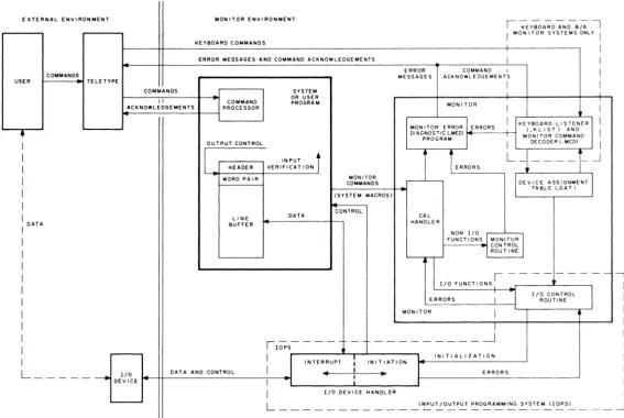
Figure 2-2 provides a more detai led representation of the monitor environment, with emphasis on command, control, and data flow. As shown, the user can initiate a command via the Teletype. In the
I/o
Monitor environment, this command can be interpreted only by a Command Processor within the system program (or user program if so designed). In the Keyboard and Background/Foreground Monitor environments, an expanded set of keyboard commands can a Iso be interpreted by a Keyboard Listener(.KUST) and acted upon by a Monitor Command Decoder (.MCD). This feature greatly extends the capabilities of the monitors and provides the user with a large repertoire of keyboard commands. The monitor shown in Figure 2-2 can represent anyone of the monitor systems, except that the
I/o
Monitor does not contain the .KUST and .MCD programs to interpret and act upon Teletype keyboard commands. The .KUST and .MCD programs are nonresident in the sense that they are overlaid by user and system programs.Each system or user program must internally set up line buffers (except when using Dump mode, discussed later) to be used in transmitting data to or from the external environment. Each line buffer of n words consists of a two-word header {referred to as a header word pair} and n -2 words of data. The system or user program can exercise control on output by modifying the header word pair, or it can verify on input by examining the header word pair. The use of line buffers is discussed in more detail
later in this chapter.
Monitor
I/o
commands {system macros} are written as part of the system or user program. In FORTRAN IV source programs, these commands are in the form of READ and WRITE statements {refer to the FORTRAN IV Manual, DEC-9A-AF4B-D}. These statements are translated by the compiler into the proper calling sequences for the FORTRAN Object Time System which provides the required monitor calls at execution time. In MACRO-9 source programs, monitor I/O commands are written as system [image:24.599.94.504.78.154.2]'"
IW
EXTERNAL ENVIRONMENT MONITOR ENVIRONMENT
I ~ Y-;O A-; D -;::N';-B;;' I KEYBOARD COMMANDS
I MON ITOR SYSTEMS ONLY I
I
ERROR MESSAGES AND COMMAND ACKNOWLEDGEMENTS I I
ERROR COMMAND I
I
COMMANDS MESSAGES ACKNQWL EDGE ME N TS
USER TELETYPE
I I
COMMANDS SYSTEM
II COMMAND OR USER PROGRAM MONITOR
ACKNOWLEDGEMENTS PROCESSOR I I
I KEYBOARD LISTENER II MON I TOR ERROR ERRORS
M(O:I\~~ T C)OM~~~D I
•
DIAGNOSTIC LMED)PROGRAM
I OUTPUT CONTROL I DECODER I.MCDI I
I
I
IN PUTi
i
ERRORS
L_
- - - - _.JI HEADER VERIFICAT ION
I WORD PAIR MONITOR
COMMANDS DEVICE ASSIGNMENT]
I (SYSTEM MACROS) TABLE LOAl)
I CONTROL
I DATA LIN E
DATA CAL
BUFFER HANDLER
I NON I/O
I FUNCT IONS
I
MON! TORI
~I CONTROL
I ROUTINE
I
11/0
FUNCTIONS' - - --I
I I/O CONTROL )
I ERRORS J ROUTINE
I MONITOR
I
I I
I
,---
- _________ -.---JI lOPS
I
:
INITIALIZATIONI INTERRUPT INITIATION
L _ _ _ _ _ _
I/O DATA AND CONTROL I 4 I
..
ERRORSI
DEvICE I
I I/O DEVICE HANDLER
L INPUT /OUTPUT PROGRAMMING SYSTEM (lOPS)
-Figure 2-2 Command, Control, and Data Flow in Monitor Environment
[image:25.776.121.688.70.450.2]macros withi n the system or user program. These system macros are expanded at assemb Iy ti me and inc lude a CAL initiated monitor call that contains the logical device number as one of the arguments.
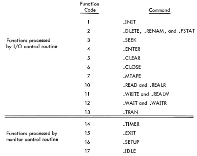
At execution time, monitor calls are processed by the CAL Handler within the monitor. Non-I/O functions are then further processed by the Monitor Control routine, and I/o functions are processed by the I/o Control routine (see Figures 2-2 and 2-3). A complete description of each of these commands is given in Chapter 3. If the original command involved is an I/o function, the I/o control routine checks the Device Assignment Table to associate the logical I/o device (specified by the system macro) to a physical I/o device. In the I/o Monitor environment, the logical/physical device associations can be modified only by reassembly. In the Keyboard and Background/Foreground Monitor environments, device associations can be modified at System Generation time, or by means of the ASSIG N keyboard command just pri or to loadi ng a system or user program. This capabi lity adds true device independence to the monitor systems.
Functions processed by I/o control routine
Functions processed by monitor control routine
Function Code
2
3
4
5 6 7
10
11
12 13 14 15 16 17
Command
.INIT
.DLETE, .RENAM, and .FSTAT .SEEK
.ENTER .CLEAR .CLOSE .MTAPE
• READ and .REALR .WRITE and .REALW .WAIT and .WAITR .TRAN
• TIMER • EXIT .SETUP .IDLE
Figure 2-3 Monitor Commands and Function Codes
[image:26.597.128.533.293.613.2]NOTE
.INIT, .READ, .WRITE, .WAIT, .WAITR, .CLOSE, • TIMER, and .EXIT are recognized by all three monitors • • SEEK, .ENTER, .FSTAT, .RENAM, .DLETE, • TRAN, .CLEAR, and .MTAPE are recognized by the Keyboard and Background/Foreground Monitors (and are ignored by the I/O Monitor) •
• SETUP is used by the Monitors in setting up the I/o skip chain and API channel registers (see Chapter 7) •
• ID LE is recogni zed by the Background/Foreground Monitor only.
When the logical/physical I/O device association has been established, the monitor passes control to the appropriate I/o device handler which initializes itself, initiates I/o, and returns control to the system or user program. As mentioned previously, the system or user program retains control unti I the specified device causes an interrupt (PI or API). At this point, it relinquishes control to the device handler to continue or complete the specified I/O operation. In either case, control is returned to the system or user program at the point where it was interrupted. The system or user program, by means of a . WAIT system macro (described in Chapter 3), can determi ne whether an input or output operati on has been completed. If the transfer of data from or to the system or user program line buffer has been completed, program execution continues; if the transfer has not been completed, control is returned to the • W AIT macro.
Additional buffering is provided by the individual device handlers as required. All device handlers are non-resident in the sense that only those handlers required by the system or user program are loaded into core.
2.2 LINE BUFFERS
Word 0
Word 1 Word 2
!
Word n-1
FiglJ"e 2-4
First Word of Line Buffer Header
Second Word of Li ne Buffer Header First Word of Data Area
l
Last Word of Data Area
Li ne Buffer Structure
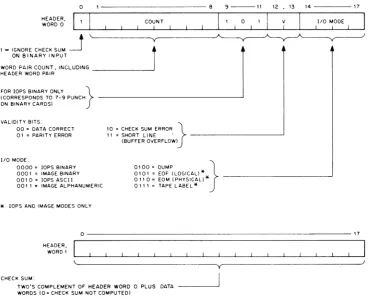
A system or user program should contain at least one line buffer for each device that is to be used. This buffer is used to set up output lines before transmittal to an output device, or to receive input lines from the associated input device. The monitor accepts commands (system macros) from system or user programs to initiate input to the line buffers and to write out the contents of line buffers. Complete descriptions of these commands are given in Chapter 3. Line buffers are internal to, and must be defined by, each system or user program. The header word pair within a line buffer is detai led in Figure 2-5. The .BLOCK pseudo operation may be used to reserve space for a line buffer. A tag is required to allow referencing by indivdual .READ and .WRITE macros. For example:
LINEIN
UNOUT
.DEC .BLOCK 52
.BLOCK 52
/creates 52-word line /buffer named UNEIN. /creates 52-word line /buffer named UNOUT.
Before output, the user must set the appropriate word pair count in bits 1 through 8 of word zero in the line buffer if they have not a Iready been set by a device handler on input. This count overrides the word count passed to lOPS by the. WRITE macro. (The word count must still be specified in the .WRITE macro for each data mode; however, it only has meaning in Dump mode since there is no header word pair.) In lOPS binary mode (discussed in Paragraph 2.3.1 .2), bits 9 through 11 should be set to 101 if the output wi II ultimately be on cards. The checksum word, the second word in the header, need not be set by the user since checksums are computed by lOPS.
Before input, the user should not be concerned with the header word pair since they wi II be set by lOPS to enable the user to determine what has happened after input has terminated.
On input, the word count specified in the .READ macro is used by lOPS to determine the maximum number of locations to be occupied by the data being read. If the word count is exceeded before input is terminated, or if there is a parity or checksum error, lOPS sets the appropriate va lidity bits in header word 0 to i ndi cate the error.
o
1 - IGNORE CHECK SUM
~
ON BINARY INPUT~~B
COUNT
r
9 - - 1 1
I 1 0 1
12 , 13 14
I V 1 I lID MODE
1
FOR lOPS BINARY ONLY }(CORRESPONDS TO 7-9 PUNCH ~~~~~~~~~~~~~~---'
ON BINARY CARDS)
VALIDITY BITS. 00 = DATA CORRECT 01 = PARITY ERROR
lID MODE.
0000 = lOPS BINARY 0001 = IMAGE BINARY 0010= lOPS ASCII 001 1 • IMAGE ALPHANUMERIC
*
lOPS AND IMAGE MODES ONLY10 = CHECK SUM ERROR }
11 = SHORT LINE . ~~~~~~~~---'
(BUFFER OVERFLOW)
0100 = DUMP } 0101 = EOF (LOGICAL! *
011 0 = EOM (PHYSICAL! * ~~~~~~~~~~---' 011 1 = TAPE LABEL"
17
0~~~~~~~~~~~~~~~~~~~~~~~~~---17
CHECK SUM: HEADER,
WORDI
~---'----y~--~~---~
TWO'S COMPLEMENT OF HEADER WORD 0 PLUS DATA - - - ' WORDS (0= CHECK SUM NOT COMPUTED)
Figure 2-5 Format of Header Word Pair
After input, the user should check the validity bits in word 0 of the line buffer header to
determine if the data was read without error. If multiple errors are detected, priority is given to a parity error over a checksum error. lOPS ignores checksum errors on binary input if bit 0 of word 0
of the line buffer header is set to 1. lOPS sets the I/O mode bits (bits 14 through 17 of word 0 of the
line buffer header) to: 6 (01102) if it senses a physical end-of-medium (such as end-of-tape in the paper-tape reader), or 5(0101 2) if it senses a logical end-of-file during an lOPS binary read.
When choosing a word count (that is, the maximum line buffer size) to specify in system
macros, both the set of possible devices and the mode of data transmission must be considered. The
max-imum line buffer sizes (including 2-word header) for standard peripheral devices, along with applicable
[image:29.597.121.491.62.366.2]Table 2-1
Maximum Line Buffer Sizes
Maximum Line
Device Buffer Size
PR (paper tape reader) 52 10
PP (paper tape punch) 52 10
TT (Teletype) 3410
CD (card reader) 52 10
LP (I i ne pri nter) 52 10
DTO-7 (DECtape) 255 10
MTO-7(magnetic tape) 255 10
OK (disk) 255 10
DR (drum) 255 10
* Data Modes are: A = lOPS ASCII B = lOPS Binary 0= Dump Mode I = I mage Bi nary
H = Image Alphanumeric
2,3 DATA MODES
Data Modes* Notes
All 3410 sufficient if A mode only, Heaaers accepted for B; generated for A, I, H
All 3410 sufficient if A mode only, Headers output for B on Iy , A,H only A Ilows for 80 10 characters,
Headers generated on input, Headers not output on output, All 52
1R
for B mode; 82 10 for I, Hmo es, Headers accepted for B; generated for A, I, H,
A only Allows for 125 10 characters, No headers output,
All
lOPS and image modes allow for All
severa I Ii ne buffers (I og ica I re-cords) per physica I block, All
All
The Input/Output Programming System allows data transmission to or from a system or user program in five different modes,
Mode lOPS Binary I mage Bi nary lOPS ASCII
Image Alphanumeric Dump
Code *
o
1
2
3 4
2-8
[image:30.600.61.554.100.555.2]2.3.1 lOPS Modes
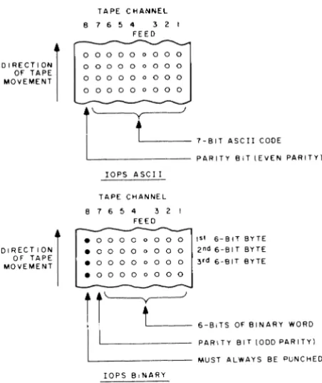
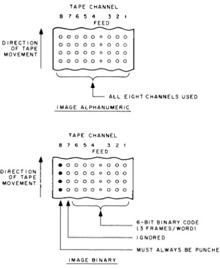
The two lOPS data modes include lOPS ASCII and lOPS binary as shown in Figure 2-6 on paper tape, and described in the following paragraphs.
DIRECTION) OF TAPE MOVEMENT
DIRECTION) OF TAPE MOVEMENT
TAPE CHANNEL 8 7 6 5 4 3 2 1
FEED
0 0 0 0 0 0 0 0 0
0 0 0 0 0 0 0 0 0 0 0 0 0 0 0 0 0 0 0 0 0 0 0 a 0 0 0
i~
I
t'-___
7-BIT ASCII CODEL . _ _ _ _ _ _ _ PARITY BIT IEVEN PARITY)
lOPS ASCII
TAPE CHANNEL 8 7 6 5 4 3 2 I
FEED
-. 0 0 0 0 0 0 0 0 1st 6-BlTBYTE • 0 0 0 0 0 0 0 0 2 nd 6-81 T BYTE • 0 0 0 0 0 0 0 0 3 rd 6-81T BYTE
. 0 0 0 0 0 0 0 0
~
'--y---Jt
6-BITS OF BINARY WORD PARITY BIT 1000 PARITY) MUST ALWAYS BE PUNCHED lOPS BINARYFigure 2-6 lOPS Mode Data on Paper Tape
2.3.1.1 lOPS ASCII - 7-bit ASCII is used by lOPS to accommodate the entire 128-character revised ASCII set (Appendix A). All alphanumeric data, whatever its original form on input (ASCII, Hollerith, etc.) or fi na I form on output, is converted i nterna Ily and stored as 5/7 ASCII. "5/7 ASCII" refers to the internal packing and storage scheme. Five 7-bit ASCII characters are packed in two contiguous
locations as shown in Figure 2-7 and can be stored as binary data on any bulk storage device. Input requests involving lOPS ASCII should be made with an even word count to accommodate the paired input.
[image:31.600.189.415.159.428.2]WORD 0
WORD 1
o ... f - - - -... 6 7 ... f - - - -__ •• 13 14 ... - -... 17 1ST CHARACTER
0 _ 2 3 "
4TH CHARACTER
2ND CHARACTER
. 9 10"
3RD CHARACTER 1-4
~ 16 17
5TH CHARACTER 4 7 -UNUSED
Figure 2-7 5/7 ASCII Packing Scheme
Non-parity lOPS ASCII occurs in data originating at a Model 33, 35, or 37 Teletype, with-out the parity option. This data always appears with the eighth (high order) bit set to 1. Apart from parity checking, the lOPS routines handle lOPS ASCII and non-parity lOPS ASCII data identically. An alphanumeric line consists of an initial form control character (line feed, vertical tab, or form feed), the body of the line, and a carriage return (CR) or ALT MODE. CR (or ALT MODE) is a required line terminator in lOPS ASCII mode. Control character scanning is performed by some device handlers for editing or control purposes (see Section 7.4 for effects of control characters on specific devices).
2.3.1.2 lOPS Binary - lOPS Binary data is blocked in an even number of words, with each block preceded by a two-word header. On paper tape (see Figure 2-6), lOPS binary uses six bits per frame, with the eighth channel always set to 1, and the seventh channel containing the parity bit (odd parity) for channels 1 through 6 and channel 8. The parity feature supplements the checksumming as a data validity provision in paper tape lOPS binary.
2.3.2 Image Modes
Image Mode data is read, written, and stored in the bi nary or a Iphanumeri c form of the source or terminal device, one character per word, as shown in Figures 2-8 and 2-9. No conversion, checking, or packing is permitted, and character scanning is generally omitted.
2.3.3 Dump Mode
Dump Mode data is a Iways binary. Dump mode is used to output from or load directly into any core memory area, bypassing the use of line buffers. Each dump mode statement has arguments defi ni ng the core memory area to be dumped. Dump mode is norma Ily used wi th bu Ik storage devi ces, although it is also possible to use it with paper tape output and input.
2.3.4
0
I
A
C
I
DIRECTION) OF TAPE MOVEMENT
DIRECTION) OF TAPE MOVEMENT
TAPE CHANNEL 8 7 6 5 4 3 2 1
FEED
0 0 0 0 0 0 0 0 0
0 0 0 0 0 0 0 0 0
0 0 0 0 0 0 0 0 0
0 0 0 0 0 0 0 0 0
~---y~---L
ALL EIGHT CHANNELS USED I MAGE ALPHANUMERICTAPE CHANNEL
8 7 6 5 4 3 2 1
FEED
. 0 0 0 0 0 0 0 0 . 0 0 0 0 0 0 0 0
. 0 0 0 0 0 0 0 0
. 0 0 0 0 0 0 0 0
IMAGE BINARY
6-BIT BINARY CODE (3 FRAMES/WORD) IGNORED
MUST ALWAYS BE PUNCHED
Figure 2-8 Image Mode Data on Paper Tape
WORD COUNT
ra
17WORD COUNT
0
rs
17 .1-2I
I
B"
I
I
C 0J
HEADER WORD PAIRABC; INS/7ASCII
I
3I
-<
A B
>-C
; .J
HEADER WORD PAIR
ABC" FO UR 8-B I T CHARACTERS (RIGHT
JUSTIFIED)
lOPS ASCII IMAGE ALPHANUMERIC
Figure 2-9 lOPS ASCII and Image Alphanumeric Data in line Buffers
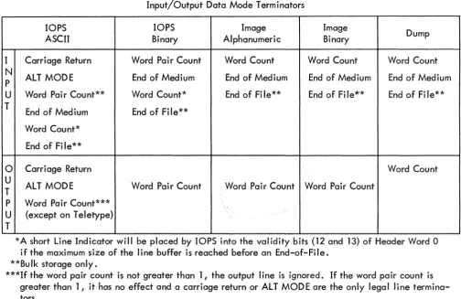
Input/Output Data Mode Terminators
[image:33.600.186.408.55.327.2]Table 2-2
Input/Output Data Mode Terminators
lOPS lOPS Image Image
Dump
ASCII Binary Alphanumeric Binary
I Carriage Return Word Pair Count Word Count Word Count Word Count N
ALT MODE End of Medium End of Medium End of Medium End of Medium P
U Word Pair Count** Word Count* End of File** End of Fi le~* End of Fi le** T
End of Medium End of File** Word Count*
End of Fi le**
0
Carriage Return Word CountU
ALT MODE Word Pair Count Word Pair Count Word Pair Count T
P Word Pair Count***
,-U (except on Teletype) T
*A short Line Indicator will be placed by lOPS into the validity bits (12 and 13) of Header Word 0 if the maximum size of the line buffer is reached before an End-of-File.
**Bulk storage only.
***If the word pair count is not greater than 1, the output line is ignored. If the word pair count is greater than 1, it has no effect and a carriage return or ALT MODE are the only legal line termina-tors.
2.4 SYSTEM TABLES
System tables used by each of the monitor systems include the Device Assignment Table (.DAT), and the System Communication Table (.SCOM). These tables are discussed in the following paragraphs.
2.4.1 Device Assignment Table (.DA T)
Both FORTRAN IV and MACRO-9 coded user programs, as well as the system programs, specify
I/o
operations with commands to logica II/o
devices. One of the monitor's functions is to relate these logical units to physical devices. To do this, each of the monitors contains a Device Assignment Table (.DAT) which has "slot" numbers that correspond directly to logicalI/o
device numbers. Each .DAT slot contains the physical device unit number (if applicable) along with a pointer to the appropriate device handler.All
I/o
communication in the monitor environment is accomplished by the logical/physical device associations provided by the Device Assignment Table. The use of the Device Assignment Table differs for each of the monitor systems, and is discussed separately for each of the monitors (Chapters 4, 5, and 6). [image:34.599.58.562.69.396.2]2.4.2 System Communication Table (.SCOM)
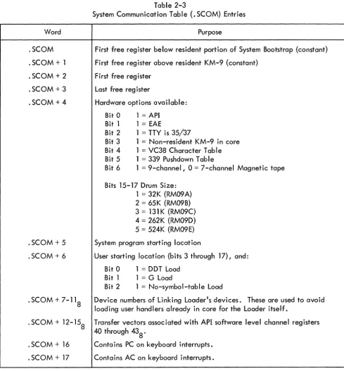
The System Communication Table (. SCOM) provides a list of registers that can be referenced by the monitor, lOPS, and system programs. A complete list of . SCOM entries, and the purpose of each, is given in Table 2-3. The System Communication Table begins at location 1008 .
Word
.SCOM .SCOM
+
1 .SCOM + 2 .SCOM + 3 .SCOM + 4.SCOM + 5 .SCOM + 6
.SCOM
+
7-11 8. SCOM + 12-158
. SCOM + 16 . SCOM
+
17Table 2-3
System Communication Table (.SCOM) Entries
Purpose
First free register below resident portion of System Bootstrap (constant) First free register above resident KM-9 (constant)
First free reg i ster Last free register
Hardware options available: Bit 0 1 = API
Bit 1 1
=
EAEBit 2 1 = TTY is 35/37
Bit 3 1 = Non-resident KM-9 in core Bit 4 1 = VC38 Character Table Bit 5 1
=
339 Pushdown TableBit 6 1 = 9-channel, 0 = 7-channel Magnetic tape
Bits 15-17 Drum Size: 1 = 32K (RM09 A) 2 = 65K (RM09B) 3 = 131K (RM09C) 4 = 262K (RM09D) 5 = 524K (RM09E) System program starting location
User starting location (bits 3 through 17), and: Bit 0 1 = DDT Load
Bit 1 1 = G Load
Bit 2 1 = No-symbol-table Load
Device numbers of Linking Loader1s devices. These are used to avoid loading user handlers already in core for the Loader itself.
Transfer vectors associated with API software level channel registers 40 through 438 .
[image:35.603.59.548.157.684.2]2.5 SPECIFYING DEVICES USED TO LINKING LOADER
When writing a MACRO-9 program that uses monitor commands {system macros}, it is necessary to use the .IODEV pseudo operation somewhere in the program to specify to the Linking
Loader which .DAT slots are to be used. The .IODEV pseudo-op causes a code to be generated that is recognized by the Linking Loader and used to load device handlers associated with specified .DAT slots. FORTRAN IV programs cause the compi ler to generate this code based on the units specified in READ and WRITE statements. {If a variable is used in a FORTRAN program to specify an
I/o
unit, handlers will be loaded for all positive .DAT slots that have handlers assigned.} The .IODEV pseudo-op has the following form.IODEV 3, 5, 6
where the MACRO-9 program containing this statement can use .DAT slots 3, 5, and 6. An error message is generated if a slot called for by a program is unassigned.
CHAPTER 3
USER PROGRAM COMMANDS (SYSTEM MACROS)
All user program commands or system macros are described in this chapter for convenient reference. All commands that apply to the
I/o
Monitor are presented first and are followed by de-scriptions of the additional commands that apply to the Keyboard and Background/Foreground Monitors, respectively. Because of the upward compatibility of monitor systems, allI/o
Monitor commands (sys-tem macros) are also used in the Keyboard and Background/Foreground Monitor environments. All Key-board Monitor commands (system macros) are also used in the Background/Foreground Monitor environ-ment. Note that all information presented in this manual for the Background/Foreground Monitor is preliminary and subject to change.NOTE
When executing a system macro, the monitor makes no attempt to save the user's accumulator and link bit.
3.1
I/o
MONITOR COMMANDS (SYSTEM MACROS)The following commands are available for use in programs that are to operate in the
I/o
Monitor environment. Each command is described in detail in the paragraphs that follow.Name
. INIT . READ • WRITE . WAIT
.WAITR
. CLOSE . TIMER . EXIT
Purpose
Initializes the device and device handler . Transfers data from the device to the line buffer . Transfers data from the line buffer to the device . Checks availability of the user's line buffer and waits if busy.
Checks availability of the user's line buffer, and provides transfer address for busy return.
3. 1 . 1 .INIT {Initialize} FORM:
VARIABLES:
EXPANSION:
.INIT a, F, R
a = Device Assignment Table (. DAT) slot number (in octal radix) F= File Type: { 0= Input File
1 = Output File
R = User Restart Address* (should be in every .INIT statement) LaC
LaC + 1
LaC
+
2 LaC + 3CAL + F7- 8 + a 9- 17
1 /The CAL handler will place the unit number (if
/applicable) associated with. DAT slot a into bits /0 through 2 of this word. **
R
n /Maximum size of line buffer associated with. DAT /slot ~, for example, 255 10 for DECtape. *** DESCRIPTION: The macro .INIT causes the device and device handler associated with. DAT slot a to be initialized • • INIT must be given prior to any I/O commands referencing .DAT slot~; a separate
.INIT command must be given for each .DAT slot referenced by the program. Each initialized .DAT slot constitutes an open file to the device handler and must be .CLOSEd. Since a • DAT slot may refer to only one type of file (input or output), only one file type specification (0 or 1) may be made in an
.INIT statement. If a . DAT slot first references an input file, then an output file (or vice versa), a second .INIT command must be executed to change the transfer direction prior to the actual data trans-fer command.
3.1.2 .READ
FORM: VARIABLES:
.READ a, M, L, W
a = • DAT slot number (octal radix)
o
= lOPS Binary 1 = Image Binary M = Data mode 2 = lOPS ASCII3 = Image Alphanumeric 4 = Dump Mode
*Has meaning only for .INIT commands referencing slots used by Teletype (the last .INIT command en-countered for any slot referencing the keyboard or teleprinter takes precedence). When the user types tP, control is transferred to R. For example, the Linking Loader takes advantage of this feature to re-start the system when a new medium has been placed in the input device.
**Has no direct effect upon the user's program, but should be noted so that no attempt will be made to use LaC + 1 as a constant.
***Size is returned by the handler so that the program, in a device-independent environment, can use it to properly set up line buffers.
EXPANSION:
L = Line Buffer address
W
=
Line buffer word count (decimal radix), including the two-word header LaCLaC + 1
LOC + 2
LOC
+
3CAL + M6- 8 + 9-17 10
L
/CAL Handler will place unit number (if applicable) /into bits
a
through 2.. DEC /Decimal radix
-W
DESCRIPTION: The . READ command is used to transfer the next I ine of data from the device assigned to. DAT slot ~ to the line buffer in the user's program. In the operation, M defines the mode of the data to be transferred; L is the address of the line buffer; and W is the number of words in the line buffer (including the two-word header).
Since I/O operations and internal data transfers may proceed asynchronously with computa-t ion, a . WAIT command muscomputa-t be used afcomputa-ter a • READ command before computa-the user acomputa-tcomputa-tempcomputa-ts computa-to use computa-the dacomputa-ta in the line buffer or to read another line into it.
When a . READ (non-dump mode) has been completed, the program should interrogate bits 12 through 13 of the first word of the line buffer header to ascertain that the line was read without error. Bits 14 through 17 should be checked for end-of-medium and end-of-file conditions.
3.1.3 .WRITE
FORM: VARIABLES:
EXPANSION:
.WRITE a, M, L, W
a
= .
DAT slot number (octal radix)a
= lOPS Binary 1=
Image Binary M=
Data mode 2=
lOPS ASCII;-';'3 = Image Alphanumeric 4 = Dump Mode
L
=
Li ne buffer addressW
=
Line buffer word count (decimal radix), including the two-word header LaCLaC + 1
LaC + 2
LaC + 3
CAL + M6- 8 to a9_ 17 10
L
/CAL Handler will place the unit number (if appli-/cable) associated with. DAT slot a into bits
/0
through2.
. DEC /Decimal radix
DESCRIPTION: .WRITE is used to transfer a line of data from the user's line buffer to the device associated with. DAT slot E1, •
• WAIT must be used after a .WRITE command, before the line buffer is used again, to insure that the transfer to the device has been completed.
On non-bulk storage devices, headers are output along with the data in lOPS binary mode only (bit 9 and 11 of header word 0 should be set to 1). On bulk storage devices, headers are output along with the data in all modes except dump mode. In image modes, the header space cannot be used for data, even though the headers are not written out. The word pair count in the header takes precedence over maximum size (or word count) in all modes and must be inserted by the user.
For both .READ and .WRITE macros, dump mode causes the transfer of the specified core area to or from one record on magnetic or paper tape. One or more blocks on DECtape or disk may be occupied by a single dump command. A subsequent .WRITE in dump mode will utilize the unfilled portion of the last block •
3.1.4 • WAIT
FORM: VARIABLES: EXPANSION:
.WAIT a
a = • DAT slof number (octal radix) LOC
LOC + 1
CAL + a9-17
12 /The CAL Handler will place the unit number (if /applicable) associated with. DAT slot a into bits /0 through 2.
DESCRIPTION: .WAIT is used to detect the availability of the user's line buffer (being filled by .READ or emptied by .WRITE). If the line buffer is available, control is returned to the user immediately after the. WAIT macro expansion (LOC + 2). If the transfer of data has not been completed, control is re-turned to the • WAIT macro. . WAIT must a Iso be used after the . TRAN command •
3.1.5 • WAITR
FORM: VARIABLES:
EXPANSION:
• WAITR a, ADDR
a = • DAT slot number (octal radix)
ADDR = Address to which control is passed if line buffer is not available for use. LOC
LOC + 1
LOC +2
CAL + 10008 + a9-17
12 /The CAL Handler will place the unit number (if /applicable) associated with. DAT slot a into bits / 0 through 2.
ADDR
DESCRIPTION: .WAITR is also used to detect the availability of the user's line buffer. If the buffer is avai lable, control is returned to the user immediately after the • WAITR macro expansion (LOC + 3). If the transfer of the data has not been completed however, control is given to the instruction at ADDR. It is the user's responsibility to return to the .WAITR to again check the availability of the buffer •
3. 1 .6 • CLOSE
FORM: VARIABLES:
EXPANSION:
.CLOSE a
a
= .
DAT slot number (octal radix) LOCLOC + 1
CAL + a9-17
6 /The CAL Handler will place the unit (if applicable) /associated with. DAT slot ~ into bits 0 through 2. DESCRIPTION: When action has been initiated (.INIT or . SEEK or • ENTER) on a file (whether the device is file-oriented or not) this action must be terminated by a .CLOSE command.
On input, it is assumed that the user is finished with the file when the .CLOSE macro is used, so the file is closed. On output, all associated output is allowed to finish and then an EOF (end-of-file) line is output before the file is finally closed. If ~ refers to a file-oriented device, any earlier fi Ie of the same name and extension, as currently referenced, is deleted from its directory after the new fi Ie is written.
3.1.7 . TIMER
FORM: VARIABLES:
EXPANSION:
• TIMER n,C
n = Number of clock increments (decimal radix)
C = Address of subroutine to handle interrupt at end of interval LOC
LOC + 1 LOC + 2
LOC + 3
CAL
14
C
. DEC /Decimal radix -n
DESCRIPTION: • TIMER is used to set the real-time clock to n increments and to start it. Each clock increment represents 1/60s for 60 Hz systems and 1/50s for 50 Hz systems.
C
o
/C + 1 is reached via JMS DAC SAVEAC: } Must not contain any Monitor CALs • in I/O or Keyboard Systems. LAC C /Restore Link RAL
LAC SAVEAC /Restore AC
XIT JMP* C
so that control will return to the originally-interrupted sequence when the interval-handling routine has been completed. The Monitor automatically reenables the interrupt system before transferring con-trol to C + 1. If the user wishes to initiate another interval at the completion of the previous interval in the subroutine specified to • TIMER, he may do so as follows:
3.1.8 . EXIT
FORM: EXPANSION:
• EXIT LOC
LAC (desired interval in 2's complement) DAC* (7
LAC C RAL
LAC SAVEAC CLON JMP* C
CAL
/Restore Li nk
/Restore AC /Turn on clock
LOC
+
1 15DESCRIPTION: • EXIT provides the standard method for returning to the Monitor after completion of a system or user program. In the I/O Monitor environment, it causes a program halt; in the Keyboard Monitor environment, it causes the non-resident monitor to be reloaded. When the reloading process has been completed, the Monitor types
MONITOR
$
on the teleprinter, indicating that it is ready to accept the next command. In the Background/Fore-ground Monitor environment, the effect of the. EXIT depends upon whether it occurs in a BACKGROUND or a FOREGROUND job (see Section 6.4.5).
3.2 KEYBOARD MONITOR COMMANDS (SYSTEM MACROS)
The commands listed below are available for use in programs that are to operate in the Key-board Monitor environment. Each command is described in detail in the following paragraphs. Refer to Chapter 5 for a complete description of bulk storage file organization.
Name
.SEEK
· ENTER · FSTAT • RENAM • DLETE .TRAN
. Cl EAR • MTAPE
Purpose
Locates file on file-oriented device and begins data input. Primes file-oriented device for output.
Checks presence of fi Ie on fi Ie-oriented device. Renames fi Ie on fi Ie-oriented device •
Deletes fi Ie from fi Ie-oriented device.
Reads or records user-specified block on bulk storage devices, providing the user with the capability to determine the structure of the fi les on the device.
Initializes file structure on file-oriented device •
Provides special commands for IBM-compatible magnetic tape •
The first se~en of the eiQht macros I isted above apply to the fi Ie-oriented devices - DECtape (DT), disk (DK), drum (DR) and magnetic tape (MT); they are ignored by nonfile-oriented devices, de-pending upon the device handler used. The eighth macro, .MTAPE, handles the nonfile-oriented func-tions of magnetic tape (REWIND, BACKSPACE, etc.). If these nonfile-oriented commands are given to file-oriented devices, they are ignored by the device handling routines. To the the .MTAPE commands, however, (REWIND TO LOAD POINT, BACKSPACE RECORD), may be used with disk drum or DECtape; when so used, they preclude the use of .SEEK or • ENTER (see Section 5.6).
3.2.1 .SEEK
FORM VARIABLES:
EXPANSION:
.SEEK a ,D
a == .DAT slot number (octal radix) D == Address of user directory entry block LOC
LOC + 1
CAL + a 9- 17 3
LOC + 2 D
/The CAL Handler will place unit number (if appli-/cable) into bits 0 through 2.
DESCRIPTION: .SEEK is used to search the directory of file-oriented device ~ for a desired file and to begin input for subsequent .READ commands. D is a pointer to (that is, the address of) a three-word entry in the user's program containing the file name and extension information. The device IS file