ISSN: 1992-8645 www.jatit.org E-ISSN: 1817-3195
WORKSPACE AND SINGULARITY ANALYSIS OF 3/3-RRRS
PARALLEL MANIPULATOR
YU QIAN, QIANG WANG, GUILAN CHEN, JINGHU YU, YI CAO
Department of Mechanism Engineering, Jiangnan University, China
E-mail: [email protected]
ABSTRACT
The workspace of manipulator can be defined as the operational area of the end effector. Because the moving platform of the parallel manipulator with six degree-of-freedom have six independence movement(movement in any direction and rotation around any direction), it means the workspace has six-dimensional, the six-dimensional workspace is difficult to be directly calculate and unable to graphic description. For the project of this article-3/3-RRRS parallel manipulator, this article will analyze the workspace of the manipulator in two cases. A discretization method is proposed for the computation of the reachable position/orientation workspace of the 3/3-RRRS parallel manipulator, respectively. Four examples of a 3/3-RRRS parallel manipulator are given to demonstrate these theoretical results; change rules are discussed in detail. As a special position and inherent attributes of the mechanism, singularity has a serious impact on the mechanism's motion control performance and drive performance. The method of searching algorithm in three-dimensional space is applied to the singularity analysis, coordinate of all possible stable positions are substituting into the Jacobian, position-singular points under given orientation condition are conformed.
Keywords: 3/3-RRRS Parallel Manipulator, Workspace Analysis, Singularity Analysis
1. INTRODUCTION
The size and shape of the workspace is an important index to measure the performance of the mechanism and the important process of the end effector's design [1]. And as a special position and inherent attributes of the mechanism, singularity has a serious impact on the mechanism's motion control performance and drive performance. Much work has been done at home and abroad during these years.
In terms of the application of numerical method, Fichter fixed three orientation parameters in six location parameters and a position parameter of the parallel manipulator and set the remaining two position parameters as variables. Then the numerical method is applied to the study of the workspace of six degree-of-freedom Stewart parallel manipulator [2]. Gosselin chooses to fix the orientation parameters of the parallel manipulator moving platform and use approach of arc intersects to determine the position workspace of the six degree-of-freedom parallel manipulator. Since the purpose of approach is solve the boundary of the workspace, the scanning is efficient and the volume of workspace can be work out[3].Similarly, Harbin Institute of Technology, Professor Chen applied the
genetic algorithm to the problem of solving process of the six degree-of-freedom space parallel robot manipulator[4]. Hunt and Fichter first use the screw theory to analyze the singularity of two different types of Steward parallel manipulator [5] and so on[6-10].
2. WORKSPACE ANALYSIS OF 3/3-RRRS PARALLEL MANIPULATOR
3/3-RRRS parallel manipulator is a new type of realizing arbitrary three-dimensional spatial motion of the parallel manipulator. The manipulator consists of a moving platform and fixed platform as well as three completely identical branched chains, among them, both the moving platform and fixed platform are equilateral triangle, P is the centroid of the moving platform, O is the centroid of the fixed platform; Between the moving and fixed platform the three branched chain by AiBi、BiCi、CiDi
(i=1 2 3) respectively in turn are connected together, between the fixed platform and AiBi, AiBi and
BiCi, BiCi and CiDi, the connection of rotation
pair; Si1,, Si2, Si3 the rotation axis respectively,
between CiDi and the moving platform the
connection of spherical hinge pair, Si4, Si5, Si6 the
ISSN: 1992-8645 www.jatit.org E-ISSN: 1817-3195
Branched chain AiBiCiDi are always whole
rotation in the same plane round the rotation pair at the point Ai, the angle between centroid in moving
and fixed platform and vertex ligature PDi as well
as OAi, is 120°mutually and respectively.
Figure 1 3/3-RRRS Parallel Manipulator Structure Diagram
3. THE INFLUENCING FACTORS OF THE WORKSPACE
The constraint of drive rotation angle directly affects the workspace of the manipulator. The six revolute joint in Ai and Bi serve as drive pair of the
3/3-RRRS parallel manipulator. Constituting the links of each of the drive pairs AiBi and BiCi are
the crankshaft type structure. So that the range of the rotation angle of the drive pairs can be expanded. So, in the solving process of workspace, define range of the rotation angle of six drive pairs γi, αi and constraint as follow:
imin i imax, imin i imax
γ ≤γ ≤γ α ≤α ≤α (1)
In the formula γimin, γimax and αimin, αimax are
given limit angle in engineering practice.
Set the vector as the direction vector which is a vertical plane of the moving platform, to indicate the vector about Euler angles η, φ and δ of the moving platform location:
T
sinδ sinη+cosδ cosη cosφ
Nvp -sinδ cosη+cosδ sinη sinφ
cosδ cosφ
⋅ ⋅ ⋅
= ⋅ ⋅ ⋅
⋅
(2)
According to the geometry relationship, rotation angle βi of the spherical hinge is:
i i i i i
β =acos(dot(Nvp,C D )/norm(C D ))
(3)
In the equation, dot, acos and norm are all function language of MATLAB. dot indicates dot product between vector Nvp and vector C Di i acos indicates to return to the arccosine. norm indicates the modulus of the vector C Di i.
Then the spherical hinge should meet the follow constraints:
imin i imax
β ≤β β≤ (4)
In the formula, βimin, βimax are the limiting
rotation angle given for engineering practice.
According to the kinematics analysis of 3/3-RRRS parallel manipulator, the manipulator structure parameters has little influence to drive. It's not the emphasis.
4. THE SOLVING METHOD OF THE WORKSPACE
By the symbolic solution of location inverse solution, we can obtain the drive joint variables corresponding to the output location of the moving platform quickly. And judge the obtained joint variables with the constrains to search out the manipulator's workspace boundary. It means that we can obtain the drive input αi(αi has two
solution), γi(i=1 2 3) what the point P's position
variables a, b, c and orientation variable η, φ, δ on the moving platform is homologous by position inverse solution. The location point can be judged whether it belong to the workspace by judging whether αi, γi, βi consistent with the constrains of
formula 1 and 4 at the same time.
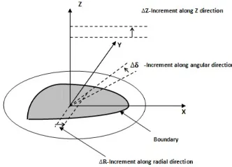
[image:2.612.93.292.160.350.2]The three-dimensional limit boundary of the parallel manipulator workspace searching shows follow:
[image:2.612.324.490.571.691.2]ISSN: 1992-8645 www.jatit.org E-ISSN: 1817-3195 5. SOLVING THE POSITION WORKSPACE
Set the structural parameters of the manipulator as: the circumcircle radius of the fixed platform R=200mm, the circumcircle radius of the moving platform r=200mm.The length of each links
are: A Bi i = 200mm , B C =150mmi i ,
i i
C D =100mm . Set the solid league coordinate
system origin P on the moving coordinate system as the research object, and the position coordinates of the point P meets the equation 5:
1
1
X=R cosσ Y=R sinσ Z=Z
⋅
⋅
(5)
In the equation, R1 ,α, Z are respectively inner
loop variables, middle loop variable and outer loop variable of the three-dimensional search.
6. POSITION WORKSPACE EXAMPLES
The accuracy and efficiency of workspace three-dimensional search greatly depend on the calculated step value. In order to obtain the position workspace of the 3/3-RRRS parallel manipulator quickly and effectively and ensure the accuracy of the position workspace, we set the steps
respectively as ΔR1=1mm,Δα=3°,ΔZ=1mm. Might
given to a group of moving platform orientation: η=0, φ=0, δ=0.
We propose two groups of range of the rotation angle of the drive angle.
The first group: -π/4≤γ1≤π/4, -7π/16≤γ2≤9π/16,
-π/8≤γ3≤7π/16; -5π/8≤α1≤5π/8, -5π/8≤α2≤5π/8,
-5π/8≤α3≤5π/8; β1≤3π/10, β2≤3π/10, β3≤3π/10
And the second group is: -3π/4≤γ1≤3π/4,
-3π/4≤γ2≤3π/4, -3π/4≤γ3≤3π/4, -3π/4≤α1≤3π/4,
-3π/4≤α2≤3π/4, -3π/4≤ α3≤3π/4, β1≤7π/20,
β2≤7π/20, β3≤7π/20.
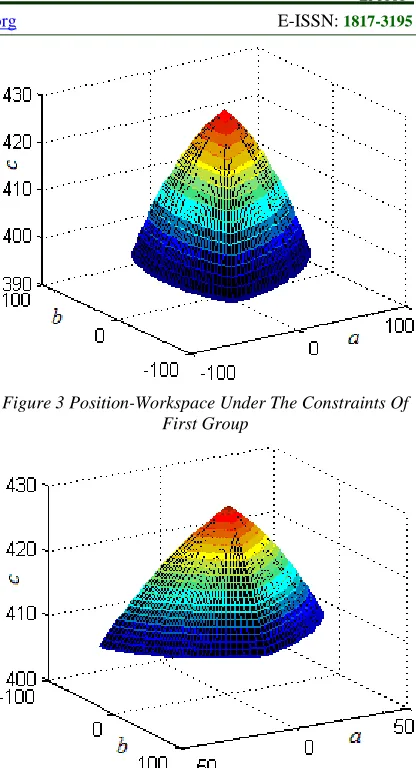
[image:3.612.315.523.71.455.2]According to the above parameters and constraint conditions, using three-dimensional limit boundary search method, we can get the three-dimensional boundary contour figure of the manipulator position workspace. Shown as figure 3 and 4:
Figure 3 Position-Workspace Under The Constraints Of First Group
Figure 4 Position-Workspace Under The Constraints Of Second Group
7. SOLVING THE ORIENTATION WORKSPACE
Keeping the manipulator's structure parameters accordance with former article, set the solid league coordinate system origin P on the moving coordinate system as the research object, and the position coordinates of the point P meets the equation 6:
1
1
η=R cosσ φ=R sinσ δ=δ
⋅
⋅
(6)
In the equation, R1, α, Z are respectively inner
loop variables, middle loop variable and outer loop variable of the three-dimensional search.
ISSN: 1992-8645 www.jatit.org E-ISSN: 1817-3195
the orientation workspace, we set the steps
respectively as ΔR1=0.001mm, Δα=3°, Δδ=π/360.
8. ORIENTATION WORKSPACE EXAMPLES
We propose two groups of the workspace and range of the rotation angle of the drive angle as follow:
The third group: the moving platform location: a=0,b=0,c=410. The range of the rotation angle of the drive angle: -π/4≤γ1≤3π/4, π/12≤γ2≤7π/12,
5π/12≤γ3≤11π/12, -3π/4≤α1≤5π/8, -3π/4≤α2≤3π/4,
-3π/4≤α3≤3π/4, β1≤7π/20, β2≤7π/20, β3≤7π/20
The fourth group: the moving platform location: a=0,b=0,c=415. The range of the rotation angle of the drive angle: -π/4≤γ1≤π/4, π/8≤γ2≤7π/12,
-π/8≤γ3 ≤5π/12, -5π/8≤α1≤5π/8, -5π/8≤α2≤5π/8,
-5π/8≤α3≤5π/8, β1≤3π/10, β2≤3π/10, β3≤3π/10
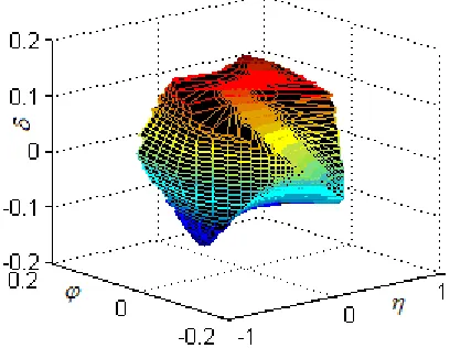
[image:4.612.316.520.66.261.2]According to the above parameters and constraint conditions, using three-dimensional limit boundary search method, we can get the three-dimensional boundary contour figure of the manipulator orientation workspace. Shown as figure 5 and 6:
[image:4.612.93.297.405.563.2]Figure 5 Orientation-Workspace Under The Constraints Of The Third Group
Figure 6 Orientation-Workspace Under The Constraints Of The Fourth Group
9. SINGULARITY ANALYSIS OF THE 3/3-RRRS PARALLEL MANIPULATOR
In this paper, on the basis of the kinematics analysis, according kinematics equals of the manipulator, we try to obtain Jacobian matrix's symbolic expressions about the six moving platform location parameters. Using the dimensional point searching method, traverse three-dimensional space completely covered by the functional requirements of the decision of all task trajectory point, obtain Jacobian matrix singular point, under the conditions of the given moving platform orientation, and draw out all the singular point in the MATLAB work environment.
As the description above, the drive input of the 3/3-RRRS parallel manipulator are αi, γi (i=1 2 3).
The motion parameters of the moving platform include positional parameters a,b,c, and orientation parameters η, φ, δ. These parameters are functions of time t. In the 3/3-RRRS parallel manipulator, according to the geometry relationship, there is:
Link length constraint equation:
2 2
i i 2i
C D =L
(7)
Two vector vertical equation:
i i i i
C D (cosγ ,sinγ ,0)=0⋅
(8)
Where in the coordinates of each of the hinge point Di in the fixed coordinate system O-xyz can
be expressed as Di : (DiX, DiY, DiZ) . Vector (cosγi
,sinγi ,0) is the vertical vector about plane
AiBiCiDi.
ISSN: 1992-8645 www.jatit.org E-ISSN: 1817-3195
2 2
i i i 2i
f = C D -L
(9)
i i i i i
F =C D (cosγ ,sinγ ,0)⋅ (10)
Taking the partial derivative of the equation 9 and 10 with respect to time t and transpose, we can obtain the equation 11 and 12:
i i i i i i
i i
i i
i i
f f f f f f
a'+ b'+ c'+ η'+ φ'+ δ'
a b c η φ δ
f f
=-( α '+ γ ' )
α γ ∂ ∂ ∂ ∂ ∂ ∂ ∂ ∂ ∂ ∂ ∂ ∂ ∂ ∂ ∂ ∂ (11)
i i i i i i
i i
i i
i i
F F F F F F
a'+ b'+ c'+ η'+ φ'+ δ'
a b c η φ δ
F F
=-( α '+ γ ')
α γ ∂ ∂ ∂ ∂ ∂ ∂ ∂ ∂ ∂ ∂ ∂ ∂ ∂ ∂ ∂ ∂ (12)
Put the velocity equations of all three branch chains on the 3/3-RRRS parallel manipulator together, written in matrix form, there is equation 13:
a 1 b 1 c 1 η 1 φ 1 δ 1
a 1 b 1 c 1 η 1 φ 1 δ 1
a 2 b 2 c 2 η 2 φ 2 δ 2
a 2 b 2 c 2 η 2 φ 2 δ 2
a 3 b 3 c 3 η 3 φ 3 δ 3
a 3 b 3 c 3 η 3 φ 3 δ 3
f f f f f f a'
F F F F F F b'
f f f f f f c'
F F F F F F η'
f f f f f f φ'
F F F F F F δ'
∂ ∂ ∂ ∂ ∂ ∂ ∂ ∂ ∂ ∂ ∂ ∂ ∂ ∂ ∂ ∂ ∂ ∂ ∂ ∂ ∂ ∂ ∂ ∂ ∂ ∂ ∂ ∂ ∂ ∂ ∂ ∂ ∂ ∂ ∂ ∂ 1 1 1 1 2 2 2 2 3 3 3 3
α 1 γ 1
1
α 1 γ 1 1
α 2 γ 2 2
α 2 γ 2 2
3
α 3 γ 3
3
α 3 γ 3
f f 0 0 0 0 α '
F F 0 0 0 0 γ '
0 0 f f 0 0 α '
=
-F F γ '
0 0 0 0
α '
0 0 0 0 f f
γ '
0 0 0 0 F F
∂ ∂ ∂ ∂ ∂ ∂ ∂ ∂ ∂ ∂ ∂ ∂
(13)
For convenience of description, might set:
[ ]
a 1 b 1 c 1 η 1 φ 1 δ 1
a 1 b 1 c 1 η 1 φ 1 δ 1
a 2 b 2 c 2 η 2 φ 2 δ 2
a 2 b 2 c 2 η 2 φ 2 δ 2
a 3 b 3 c 3 η 3 φ 3 δ 3
a 3 b 3 c 3 η 3 φ 3 δ 3
f f f f f f
F F F F F F
f f f f f f
P =
F F F F F F
f f f f f f
F F F F F F
∂ ∂ ∂ ∂ ∂ ∂ ∂ ∂ ∂ ∂ ∂ ∂ ∂ ∂ ∂ ∂ ∂ ∂ ∂ ∂ ∂ ∂ ∂ ∂ ∂ ∂ ∂ ∂ ∂ ∂ ∂ ∂ ∂ ∂ ∂ ∂
(14)
[ ]
1 1 1 1 2 2 2 2 3 3 3 3α 1 γ 1
α 1 γ 1
α 2 γ 2
α 2 γ 2
α 3 γ 3
α 3 γ 3
f f 0 0 0 0
F F 0 0 0 0
0 0 f f 0 0
Q =
0 0 F F 0 0
0 0 0 0 f f
0 0 0 0 F F
∂ ∂ ∂ ∂ ∂ ∂ ∂ ∂ ∂ ∂ ∂ ∂
(15)
Then [P],[Q] are called Jacobian matrix of this manipulator. Therefore, the equation 13 can also be written as follows:
[ ]
[ ]
1 1 2 2 3 3 α ' a' γ ' b' α ' c'P = - Q
γ ' η'
φ' α '
δ' γ '
(16)
According to equation 16, we can define two types of singular points as follows:
The first kind of singular point: the point of
meeting Det(P)=0 and Det(Q)≠0.
The second kind of singular point: the point of
meeting Det(Q)=0 and Det(P)≠0.
10. SOLVING THE SINGULARITY
The solution process of singular configuration will be based on kinematics inverse solution and manipulator geometry relations, using the method of three-dimensional search, search method is shown in Figure 2. Similarly, since the taken step size of the calculate will decide whether all the singular points can be searched, in order to quickly and effectively obtain all singular points of the 3/3-RRRS parallel manipulator, might set the step
as:ΔR1=0.01mm , Δα=3°, ΔZ=1mm.
ISSN: 1992-8645 www.jatit.org E-ISSN: 1817-3195
set the manipulator structure parameters as above.
And set the moving platform orientation η=0, φ=0,
δ=0.
11. SOLVE THE FIRST KIND SINGULAR POINTS
By kinematics inverse solution, every group moving platform location corresponds to one group γi and eight groups αi. That is, there are eight
groups Ci coordinate combination. So according to
the eight groups different Ci coordinate
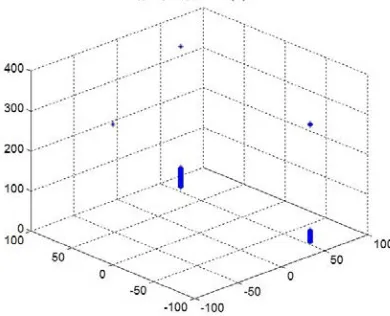
[image:6.612.103.298.313.471.2]combination, we need to obtain eight different corresponding Jacobian matrixes, and work out the value of the corresponding Jacobian matrix's determinant. The obtained points which make Det(P)=0 are all singular points. The first kind singular points figure in 3/3-RRRS parallel manipulator is shown as figure 7:
Figure 7 The First Kind Singular Points
Easy to know, each singular points above is not in the position workspace which is determined by the condition of the moving platform orientation η=0, φ=0, δ=0.
12. SOLVE THE SECOND KIND SINGULAR POINTS
Similar to the solving process of the first singular points, the position output value of the moving platform need to plugged in eight different Jacobian matrixes. The obtained points which make Det(Q)=0 are all singular points. The number of the second singular point of the 3/3-RRRS parallel manipulator is zero by solving.
We know, through the analysis of the singular figure in example, that almost all the corresponding singular points under the condition of the moving platform orientation η=0, φ=0, δ=0 are below the height of 100mm in the 3/3-RRRS parallel
manipulator. And the two straight lines formed by these points are both parallel to the Z axis, and these points are all not in the corresponding space of the orientation. Therefore, the workspace in the condition of meeting the preset constraints is the final actual workspace.
SUMMARY
This paper mainly analyses the workspace and singularity of the 3/3-RRRS parallel manipulator. In the different conditions of a given position and orientation, according to the different actuator angle constraint and other structural constraints, this paper has successfully solved the workspace figures having a certain geometry of the three-dimensional space. At the same time, all the singular point is obtained in this orientation, and shown in the three-dimensional figure.
ACKNOWLEDGEMENTS
This work was supported by the National Natural Science Foundation of China (Grant No. 509050 75), the Open Project of State Key Laboratory of Fluid Power and Mechatronic Systems (Grant No. GZKF-201105), the Research and the Innovation Project for College Graduates of Jiangsu Province (Grant No. CXZZ11-0482) and the Program for Innovative Research Team of Jiangnan University (Grant No. 2009CXTD01).
REFRENCES:
[1] Anjan K D, Chen I-Ming, Song H Y.
“Workspace generation and planning singularity-free path for parallel manipulators”, Mechanism and Machine Theory, Vol. 40, No. 1, 2005, pp. 776-805.
[2] Fichter E F. “A Stewart Platform-Based
Manipulator: General Theory and Practical
Construction”, The International Journal of
Robots Research, Vol. 5, No. 2, 2006, pp. 157-182.
[3] Gosselin C M, Lavoie E. Toutant P. “Robotics
Spatial Mechanisms and Mechanical systems”, Journal of Applied Mechanics, Vol. 45, No. 1, 2002, pp. 323-328.
[4] Z. L. Chen, X. S. Chen, T. Xie. “Solve the
synthesis problem of the given workspace by
Genetic Algorithm ”, Chinese Mechanical
ISSN: 1992-8645 www.jatit.org E-ISSN: 1817-3195
[5] Hunt K H, Primrose E J E. “Assemble
configurations of some in parallel-actuated
manipulators ”, Mach Mech Theory, Vol. 28,
No. 1, 2003, pp. 31-42.
[6] Yi Cao, Zhen Huang, Hui Zhou, Weixi Ji.
“Orientation-Workspace Analysis of a Special Class of the Stewart-Gough Parallel
Manipulators”, Robotica, Vol. 28, No. 7,
2010, pp. 989-1000.
[7] Yi Cao, Zhen Huang, Qiuju Zhang, Hui Zhou.
“Orientation-Singularity and Nonsingular Orientation-Workspace Analysis of the Semi-Regular Stewart-Gough Platform
Manipulator”, Advanced Robotics, Vol. 24,
No. 15, 2010, pp. 2119-2135.
[8] Stewart D. “A Platform with six degrees of
freedom”, Proceedings of the Institution of
Mechanical Engineers, Part A: Journal of Power and Energy, Vol. 180, No. 15, 1995, pp. 371-386
[9] Chan Wing, Yan Jing. “Homotopy iteration
method and applied to the positive position of the general 6-SPS parallel robot mechanism “, Mechanical Science and Technology, Vol. 12, No. 2, 2007, pp. 404-422.
[10] Yi Cao, Hui Zhou, Weixi Ji, Qiuju Zhang,
Baokun Li. “Singularity Kinematics Principle and Position-Singularity Analyses of the 6-3 Stewart-Gough Parallel Manipulators”. Journal of Mechanical Science and Technology, Vol. 25, No. 2, 2011, pp. 513-522.
[11] Yi Cao, Hui Zhou, Qiuju Zhang, Weixi Ji.