ISSN:1992-8645 www.jatit.org E-ISSN:1817-3195
FPGA IMPLEMENTATION OF A NEW BCH DECODER USED
IN DIGITAL VIDEO BROADCASTING SATELLITE
-SECOND GENERATION (DVB-S2)
1*EL HABTI EL IDRISSI ANAS,1, 2EL GOURI RACHID,3AHMED LICHIOUI,1HLOU
LAAMARI
1Laboratory of Electrical Engineering and Energy System. Faculty of Sciences, University Ibn Tofail
Kenitra, Morocco
2
Laboratory of Electrical Engineering and Telecommunications Systems, National Schools of Applied
Sciences, University Ibn Tofaïl Kenitra, Morocco
3National Society of Radio and Television (SNRT), Rabat, Morocco
*E-mail: [email protected]
ABSTRACT
The Bose, Chaudhuri, and Hocquenghem (BCH) codes are being widely used in variety communication and storage systems. In this paper, a simplified algorithm for BCH decoding is proposed in order to reduce the implementation complexity. Error locator polynomial with Peterson algorithm is proposed for both a quick result and very low components instead of the Berlekamp’s algorithm that uses the iterative method. In addition, a modified Chien search block is proposed to reduce the hardware complexity. This algorithm reduces the number of logic gates. Consequently, it reduces the power consumption with a percentage which can achieve 32 % compared to the basic algorithm. We developed the design of the proposed algorithm, we generated and simulated the hardware description language source code using Quartus software tools and finally we implemented the new algorithm of BCH decoder on FPGA card.
Keywords: FPGA implementation, BCH decoder, add syndromes, iterations, Digital Video
Broadcasting-Satellite-Second Generation
1.
INTRODUCTIONError correcting codes are used in satellite communication, cellular telephone networks, body area networks and in most of the digital applications. Few of them are BCH, Turbo, Reed Solomon, Hamming and LDPC. These codes differ from each other in their implementation and complexity [1]. The binary BCH codes were discovered in 1959 by Hocquenghem and independently in 1960 by Bose and Ray-Chaudhuri. Later, Gorenstein and Zierler generalized them to all finite fields [2]. The aim of this work is to optimize the BCH decoder compared to the basic one used nowadays in several fields like DVB-S2. First, we started by a reduction of iterations in the syndrome block. Second, we used a new method in order to determinate the error locator polynomial instead of Berlekamp’s algorithm. Third a new algorithm was used in the Chien search block so as to reduce a large number of logic gates. Fourth the three Blocks were grouped into a single circuit
using the code BCH (3240, 3072, 12) used in DVB-S2 Bearing in mind many works have been done in this field [3][4]. Finally, the proposed algorithm was implemented on a Xilinx Spartan 3E-500 FG 320 FPGA (xc3s500e-5fg320).
2.
BACKGROUND AND RELATED WORKThree main steps for BCH decoding are represented as follows:
Step 1: Computation of syndromes.
Step 2: Berlekamp-Massey algorithm.
Step 3: detection of error position using
Chien Search Block.
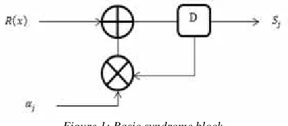
2.1 Syndrome Block
The BCH code is characterized as (n, k, t), where n is the code word length, k is the information length, and t is the error correction capability. The coefficients (r0, r1… rn-1) can be represented as a
received polynomial [5], R (x) = r0+ r1x + r2x2… +
rn-1x n-1
ISSN:1992-8645 www.jatit.org E-ISSN:1817-3195
Si= R (α i ) =
1 0 n j riαi.j
(1)
The hardware algorithm for BCH syndrome Block is defined in Figure 1, where R (x) represents the received code word, αjis the primitive element and
[image:2.612.92.300.188.279.2]Sjare the values of syndromes with 1≤ j ≤ 2t.
Figure 1: Basic syndrome block
For each Syndrome Sj, where 1 ≤ j ≤ 2t, n iterations are needed to compute the coefficient of Syndrome Polynomial, knowing that all the syndrome coefficients will be equal to 0 if the received code word is correct with at least one coefficient different from 0 if the code word is not correct.
2.2 Berlekamp’s Algorithm
Berlekamp’s algorithm [6] is a more efficient iterative technique of solving equations that also overcomes the problem of not knowing ν. This done by forming an approximation to the error locator polynomial, starting with A(x) = 1. Then at each stage, an error value is formed by substituting the approximate coefficients into the equations corresponding to that value of ν. The error is then used to refine a correction polynomial, which is then added to improve the approximate A (x). The process ends when the approximate error locator polynomial checks consistently with the remaining equations.
2.3 Chien Search Algorithm
This algorithm can detect the error position by calculatingɅ (α-i), where:Ʌ (x) is the error locator polynomial. For the case of RS (n, k) we must calculate:Ʌ (α-(n-1)),Ʌ (α-(n-2))…Ʌ (α-1),Ʌ (α-0). If the expression reduces to 0 Ʌ (α-i) = 0, then the position i contains an error else the position does not contain an error.
3.
PROPOSED BCH DECODERThe proposed BCH decoder contains three main steps represented as follows:
Step 1: proposed syndrome block.
Step 2: Calculation of error locator
polynomial through the
Berlekamp- Step 3: proposed Chien Search Block.
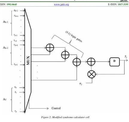
3.1 Proposed Syndrome Block
The proposed syndrome block is based on a simple factorization [7] of the received code word so as to determinate the add syndromes. Consequently, we can design another circuit of the Syndrome Block i.e. we can reduce latency by decreasing the number of iterations compared to the basic circuit.
Generally for a code characterized as (n, k, t), where n is the code word length, k is the information length and t is the error correction capability.
We have:
=
∑
=0,− ∗ (2)= ∑ , ( / ) (3)
Where:
J is an odd number J divides n
SJare the odd numbers
The logic circuit for Proposed Syndrome Block is represented in Figure 2.
3.2 Determination of Error Locator Polynomial Using Peterson Algorithm
This algorithm consists to solve the matrix equation Λ. A = S where:
Λ = ⎝ ⎜ ⎛ 1 ⋮ 0 ⋮ ⋱ 0 0 ⋮ 0 0 ⋮ ⎠ ⎟ ⎞
, A =
⎝ ⎜ ⎛ ⋮ ⎠ ⎟ ⎞
and S =
⎝ ⎜ ⎛ ⋮ ⎠ ⎟ ⎞
The advantage of this algorithm is to use a direct method instead of the iterative method like Berlekamp’s algorithm and hence it presentsboth a quick result and very low complexity compared to the Berlekamp’s algorithm. For the case of BCH (15, 7, 2) we have: N = 15, k = 7 and t = 2 => Λ (x) = A2X2+ A1X + 1 as degree 2.
To calculate A2 and A1 we solve the matrix
equation:
1 0 = (4)
ISSN:1992-8645 www.jatit.org E-ISSN:1817-3195
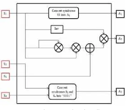
3.3 Hardware for Peterson Algorithm
[image:3.612.90.302.138.321.2]The hardware algorithm for BCH (15, 7, 2) code is represented as follows:
Figure 3: Peterson algorithm cell
The hardware arrangement used for Peterson algorithm, shown in Figure 3, can be characterized by different blocks such as the block “Convert syndrome into A1”, which means that whatever the value of S1, A1 will be equal to “0001”. The block “Convert syndromes S2 and S4 provides “0001” whatever the values of S2 and S4 knowing that: for the case of BCH (15, 7, 2) A2 = “0001”.
3.4 Proposed Algorithm for Chien Search Block
The proposed chien search block is based on a simple factorization of the error locator polynomial. Besides, we can design another circuit of the Chien Search Block i.e. this algorithm presents both a large minimization of components [8], and a low power consumption compared to the basic algorithm. Generally for BCH (n, k, t):
Ʌ (X) = AnXn +An-1 Xn-1 + … A1X + A0
= X (AnXn-1+ An-1Xn-2+ … + A1) + A0
= X (X (AnXn-2+ An-1Xn-3+ … + A2) + A1) + A0
= X (X (X (……..X (AnX + An-1) + An-2) +…)
+A2) + A1) + A0
Where the coefficients A1, A2… An-1, An differ
from 0. The corresponding logic circuit is represented in Figure 4.
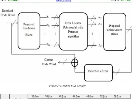
3.5. Hardware and Simulation for Proposed BCH Decoder
The hardware algorithm and simulation for proposed BCH decoder are represented respectively in figures 5 and 6.
4.
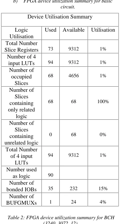
COMPARISON OF ALGORITHMS [image:3.612.311.526.252.677.2]According to the tables 1and 2 which show the FPGA device utilization summary for BCH (15, 7, 2) and BCH (3240, 3072, 12) codes using the proposed BCH decoder, we can conclude that: The proposed algorithm presents a low complexity and a very good performance compared to the basic algorithm.
Table 1: FPGA device utilization summary for BCH (15, 7, 2).
a) FPGA device utilization summary for modified circuit.
Device Utilisation Summary Logic
Utilisation Used Available Utilisation Total Number
Slice Registers 50 9312 1% Number used as
Flip Flpos 46 Number used as
Latches 4
Number of 4
input LUTs 65 9312 1%
Number of
occupied Slices 47 4656 1% Number of
Slices containing only
related logic
47 47 100%
Number of Slices containing unrelated logic
0 47 0%
Total Number
of 4 input LUTs 90 9312 1% Number used as
logic 65
Number used as a route-thru 25
Number of
bonded IOBs 18 232 7%
IOB Latches 3 Number of
BUFGMUXs 2 24 8%
Average Fanout of Non-Clock
Nets
ISSN:1992-8645 www.jatit.org E-ISSN:1817-3195
Figure 2: Modified syndrome calculator cell
[image:4.612.186.438.486.646.2]ISSN:1992-8645 www.jatit.org E-ISSN:1817-3195
[image:5.612.94.521.366.610.2]Figure 5: Modified BCH decoder
Figure 6: VHDL Simulation of Modified BCH decode with Quartus
Where syt1, syt2, syt3, syt4 represent the four syndromes, EL1, EL2, EL2 represent the
ISSN:1992-8645 www.jatit.org E-ISSN:1817-3195
b) FPGA device utilization summary for basic circuit.
Device Utilisation Summary
Logic Utilisation
Used Available Utilisation
Total Number
Slice Registers 73 9312 1% Number of 4
input LUTs 94 9312 1%
Number of occupied
Slices
68 4656 1%
Number of Slices containing only related
logic
68 68 100%
Number of Slices containing unrelated logic
0 68 0%
Total Number of 4 input
LUTs
94 9312 1%
Number used as logic 90 Number of
bonded IOBs 35 232 15%
Number of
[image:6.612.89.300.115.508.2]BUFGMUXs 1 24 4%
Table 2: FPGA device utilization summary for BCH (3240, 3072, 12).
Recources proposed algorithm
basic algorithm
Device Xilinx Spartan 3E (xc3s500e-5fg320)
BCH (n, k, t) BCH (3240, 3072,12) Number of
occupied Slices 280 408
Total Number
Slice Registers 296 432
Number of 4
input LUTs 389 564
Number used as
logic 372 540
5.
CONCLUSIONhave optimized three blocks in the BCH decoder beginning with the syndrome block then the Peterson algorithm block and the Chien search block. The three Blocks were grouped into a single circuit using the BCH (3240, 3072, 12) code used in DVB-S2. This algorithm reduced both a large number of minimized logic gates and the power consumption with a percentage which can reach 32% compared to the basic algorithm. The proposed algorithm has been implemented on a Xilinx Spartan 3E-500 FG 320 FPGA (xc3s500e-5fg320). The results in Tables 1 and 2 show that the proposed algorithm requires reduced hardware resources compared to the basic algorithm.
REFRENCES:
[1] P. Mathew, Lismi Augustine, Sabarinath G and
Tomson. Devis, “HARDWARE
IMPLEMENTATION OF (63, 51) BCH ENCODER AND DECODER FOR WBAN USING LFSR AND BMA”, International Journal on Information Theory, Vol. 3, No. 3, 2014, pp. 1–11.
[2] M. Prashanthi, P. Samundiswary, “An Area Efficient (31, 16) BCH Decoder for Three Errors”, International Journal of Engineering Trends and Technology, Vol. 10, No. 13, 2014, pp. 616–620.
[3] A. El habti, R. El gouri and H. Laamari,“A low power error detection in the Chien Search Block for Reed-Solomon code”, Proceedings of International Conference on Complex Systems (ICCS), Agadir Morocco, November 5-6, 2012, pp. 1-3.
[4] R. Huynh, GN. Ning and Yang Huazhung, “A Low Power Error detection in the syndrome calculator Block for Reed-Solomon codes RS: (208,188)”, J. Tsinghua Science and Technology, Vol. 14, No. 4, 2009, pp. 474-477. [5] Y. Lee, H. Yoo and IC. Park, 2014.
“SMALL-AREA PARALLEL SYNDROME
CALCULATION FOR STRONG BCH DECODING”, proceedings of International Conference on Acoustics, Speech and Signal Processing (ICASSP), Kyoto, March 25-30, 2012, pp. 1609-1612.
ISSN:1992-8645 www.jatit.org E-ISSN:1817-3195
[7] A. El habti, Rachid El gouri, Ahmed Lichioui and Hlou Laamari, “Conception of a new Syndrome Block for BCH codes with hardware Implementation on FPGA Card”, Int. Journal of Engineering Research and Applications, Vol. 5, No. 5, 2015, pp. 80-85.