AN INTRODUCTION TO
DIGIIAI.
An Introduction
to
DIGITAL COMPUTERS
volume 2
FOR TRAINING PURPOSES ONLY
This manual was compiled and written by members of the
instructional staff of
CONTROL DATA INSTITUTE CONTROL DATA CORPORATION CDI 60241700
Former publication number: 091266A.
Foreword
Now that you have completed Volume I, you should understand number systems and how a computer is programmed in machine language, assembler language, and compiler language. You know what to expect the computer to do, even though you may not know how it is done.
The overall objective of Volume II is to teach you how the computer operates internally. This objective will be accomplished if you understand each subject as it is discussed and how that subject forms an integral part of the computer concept.
General Table of Contents
Volume I INTRODUCTION AND PROGRAMMING Chapter I
Chapter II Chapter III Chapter IV
Introduction
History and Applications Computer Mathematics Programming
Volume ·11 COMPUTER HARDWARE
Chapter V Boolean Algebra
Chapter VI Introduction to Logic Circuitry Chapter VII Arithmetic Section
Chapter VIII Computer Storage Chapter IX Control Section Chapter X Input/Output Section
Volume III SUPPLEMENTAL AND REFERENCE MATERIAL Chapter XI
Glossary Appendix A Appendix B
A Digital Computer, From Concept to Customer
Contents
CHAPTER V BOOLEAN ALGEBRA Introducticn
A History of Boolean Algebra • Concepts of Boolean Algebra
Fundamental Rules of Boolean Algebra • Veitch Diagrams
Answers to Review Questions Answers to Boolean Laws Summary
CHAPTER VI INTRODUCTION TO LOGIC CIRCUITRY Introduction • •
Fam1ies of Logic Circuits
Building Blocks of Logic Circuitry • Registers and Types of Transmission Operation of Registers
Answers to Logic Exercises Answers to P Register Exercises Summary
CHAPTER VII ARITHMETIC SECTION OF A COMPUTER Introduction • • •
Review of Logic
Functions of Arithmetic Section
· • 5-1
• 5-1 • 5-16 • 5-25 • 5-60 • 5-69 · • 5-72 · 5-77
• 6-1 • • 6-8 • 6-39 • 6-53 • • 6-60 • 6-68 • • 6-70 6-71
CHAPTER VIII COMPUTER STORAGE Introduction •
Designs of Storage rrevices Sequential Access Devices Random Access Storage Devices Sunnnary
Answers to Review Questions
CHAPTER IX CONTROL SECTION Introduction •
Computer Block Diagram • Detailed Circuit Analysis Sunnnary
Answers to Review Questions
CHAPTER X INPUT-OUTPUT SECTION Introduction •
I/O Block Diagram I/O Instructions
Functional Analysis of I/O Equipments Cabling
Sunnnary
Answers to Review Questions
8-1 8-3 8-4 8-9 8-41 8-47
9-1 9-2 9-10 9-24 9-25
chapter v
CHAPTER V BOOLEAN ALGEBRA
INTRODUCTION
A digital computer is comprised of thousands of logic circuits, each capable of indicating yes or no, true or false, or logical "1" or logical "0". The output of a given circuit may be a blip on an oscilloscope to the Customer Engineer, a light on the console to the computer operator, or an astounding spectacle to a casual observer. A logical "l" from a given circuit
represents an equation or combination of terms which can be analyzed by using Boolean Algebra much the same as an ordinary equation is analyzed by using ordinary algebra.
Boolean Algebra is a unique logical science and is, therefore, governed by a set of parametric laws, or statements.
The objectives of this Chapter are to teach you the fundamental concepts of Boolean Algebra, the laws that circumscribe its boundaries, and the manner in which logical circuits can be analyzed to determine output equations. This chapter will also teach you how to use the Veitch Diagram to simplify a Boolean expression but only after you understand t he laws which justify the diagram.
A HISTORY OF BOOLEAN ALGEBRA
In 1854 an English mathematician, George Boole, composed the treatise, An Investigation of the Laws of Thought on Which are Found the Mathematical Theories of Logic and Probabilities. This treatise was to perform a
-mathematical analysis of logic. His objective is perhaps best introduced by the following quotation from his first chapter:
The design of the following treatise is to investigate the fundamental laws of those operations of the mind by which reasoning is performed; to give expression to them in the symbolical language of a calculus, and upon this foundation to establish the science of Logic and to construct its method; to make that method itself the basis of a general method for the application of the mathematic doctrine of
probabilities; and, finally, to collect from the various elements of truth brought to view in the course of these inquires some probable intimations roncerning the nature and constitution of the human mind.
As a result of his investigation and the construction of a logical algebra, subsequent mathematicians and logicians were led into several new fields of mathematics. From the philosophy to the maturing mechanics developed an algebra which is now used in the design of digital computer logic circuitry. This algebra is called Boolean Algebra.
In 1938 a research assistant, Claude E. Shannon, in the department of electrical engineering at Massachusetts Institute of Technology, suggested that Boolean Algebra be used to solve problems in relay switching circuit design. This method was suggested in his M.S. degree thesis entitled,
"A Symbolic Analysis of Relay and Switching Circuits". This paper presented a method for representing any circuit consisting of combinations of
switches and relays by a set of mathematical expressions. The calculus used was shown to be exactly analogous to the calculus of propositions used in the field of symbolic logic. The basic techniques described by Shannon were adopted almost universally for the design and analysis of switching circuits. Because of the analogous relationship between the action of relay, vacuum tube, and transistor circuits, the same techniques were developed for the design of the switching circuits used in modern high speed computers. There are several advantages in having a mathematical technique for the description of switching circuits. For one thing, it is far more convenient to calculate with expressions used to represent sWitching circuits than it is to use schematic or even logic diagrams. Just as an ordinary algebraic expression may be simplified by means of the basic theorems, the expression describing a given switching circuit network may also be reduced or
simplified. This enables the designer of the logic to simplify the circuitry used, achieving economy of construction and reliability of operation. Boolean Algebra also provides an economical and straightforward way of describing the
circuitry used in computers. In all, a knowledge of Boolean Algebra is indispensable in the computer field.
There are some basic differences between Boolean Algebra and ordinary algebra, the letter symbols may take a large number of values whereas in Boolean Algebra, they may assume only one of two possible values (consistant with the binary number system). Because of the binary nature of the variables involved, Boolean Algebra is much ~impler than ordinary algebra. In ordinary algebra, the values have a numerical significance; in Boolean Algebra, only a logical significance. In order to further illustrate the value and principles of Boolean Algebra, the following self-teaching device, in the form of a story about baseball has been included. It shows the flexibility of Boolean Algebra, used in this case to explain the conditions surrounding a baseball game. It shows the brevity that can be gained for a given situation, as exemplified by the final equation developed for this baseball analogy.
FACTORS you must consider before going to a baseball game are: Do you have $10.00 you could spend?
If you have $10.00 to spend letls call it IIAII to prevent having to rewrite this longer statement over and over and over.
A
=
$10.00 (This could also be called the PRESENCE of $10.00) If you do not have $10.00, then you do not have lIA II.INot IIA!! is written A
I
not A =A
= $10.00A
=
$10.00 (This could also be called the ABSENCE of $10.00) Another factor to be considered: Is it Saturday? Let liB!! stand for Saturday. Thus:B = Saturday
B
=
Not SaturdayWe can then state: "We will go to the baseball game if we have $10.00 AND itls Saturday!!!
As long as we are shortening everything, let a dot
[!]
represent AND.How would the statement: IIWe will go to the baseball game if we have $10.00 AND it r s Saturday! II be written symbolica lly?
Mean the same thing
{
Wefre going to the baseball game if
we have $10.00 AND it's Saturday.
As for multiplication in regular algebra, the • is sometimes omitted and the relationship is simply inferred. Thus A and B, A·B and AB all represent the same condition. I'm not much for baseball, but if I have $10.00 AND it's Saturday AND the game is with the Yankees, I'll go!
How would this additional factor be represented in the entire equation if we again abbreviate and have
fIe
fl stand for Yankees?ANSWER:
--'--"-'-1
IABC - We're going to go: with the Yankees.
We have $10.00 AND it's Saturday AND the game is
I
Review: A and B
A-B
AB
}
All mean the same thing {
We are going to the baseba 11 game if
we have $10.00 AND it's Saturday.
What if it's raining? Letting "D" sta'nd for raining, we can say: lIABCD; if all are true, or present, we'll go".
Notice the D in the expression. We said that liD" stood for raining; thus, we'll go if itls NOT raining or D.
ABCD means: "I'll go to the baseball game if I have $10.00 AND it's Saturday AND the game is with the Yankees AND it's not raining.
What would the expression be if I said I would go if I had $10.00, it was Saturday, the game was with the Yankees, and it was not raining OR I would go if I had $10.00, it was Saturday, the game was with the Yankees, and it was raining and I had a raincoat.
Let liE" = raincoat and the plus sign
EEl
represent ORWrite the new expression here
ANSWER:
ABCD = 1111 go. (I have $10.00 AND it1s Saturday AND Yankees AND itfs not raining.
ABCDE
=
1111 go. (I have $10.00 AND itts Saturday AND Yankees AND raining AND I have a raincoat:)OR
ABeD
+
ABCDE = 1111 go as long as either the top statement (called the first TE&~) or the bottom statement (called the second TERM) is true:Review: A and B
A"B
AB
}
All mean the same thing {
We I re going to the baseba 11 game if
we have $10.00 AND itts Saturday
ABC - We!re going to go: We have $10.00 AND it's Saturday AND the game is with the Yankees.
Everything else has been abbreviated, let's abbreviate the presence or absence of A condition.
If something is true or present call it a
"I"
If something is false or absent call it a"0"
ABCD 1 and 1 and 1 and 1
=
1 (do not add, just consider 1 and 1=
1) Note that the l's and O's are used to indicate the state of the individual factors or items as well as the validity of the entire statement.REVIEW how Band D were defined if you have difficulty with the last statement. Following o~r ~aseba11 story and the use of lIs and O's, evaluate the
expression ABCD which means:
I do not have $10.00 and the game is with the Yankees on a sunny Saturday.
ANSWER:
ABCD ;:-.:: 0 If all or any conditions are absent we do not go to the game. In this case A
=
0, B = 1, D = O. Therefore, the entire expression is 0 since° .
1 • 1 . 1 = 0 because not all the factor were true.Review:
A and B }
A • B AB
All mean the same thing
f
We J re going to th" baseba 11 game i fl
we have $10.00A~
it'. Saturday. ABC Weire going to go: \.Je have $10.00 AND it's Saturday AND the game is ~Niththe Yankees.
ABeD
=
Ifll go. (I have $10.00 AND it's Saturday AND Yankees AND it1s not raining)ABCDE 1111 go. (I have $10.00 AND itTs Saturday AND Yankees AND raining AND
I have a raincoat. OR
ABeD + ABCDE
=
Itll go as long as either the first term OR the second term is true.ABeD
+
ABGDE = 1 If all conditions are present, then we go to the game.If an entire statement is equal to !11fT , at least one term is true or
satisfied (equal to 1).
If an entire statement is equal to fTOfT, all terms are false or unsatisfied (equal to !lOfT).
How would the statement ABCD
+
ABCDE have to be amended in order to include going to any world series game under any condition (use G to represent thiscondition).
ANSWER:
ABeD + ABCDE +G ~ 1
Review:
{
We're going to the baseball game if All mean the same thing
we have $10.00 AND it's Saturday.
'ABC - We1re going to go:
the Yankees.
He have $10. 00 AND it I S Saturday AND the game i.s '" itit
I
ABCD ~ 1111 go. (I have $10.00 AND it's Saturday AND Yankees AND it!s ?ot raining)
ABCDE ~ I t11 go. (I have $10.00 AND it's Saturday A~~ Yankees AND raining AND
I have a raincoat.) OR
ABeD
+
ABCDE I'll go as long as either the first term OR the second term is true.ABCD
+
ABCDE ~ 1ABCD +ABCDE +G - 1
If all factors within a term are present, then we go to the game ..
If at least one factor i~ each term is absent, we do not go to the game. ABCD = 0
(I have $10.00 AND it's Saturday AND Yankees AND it's nqt raining) OR (I have $10.00 ANDit1s Saturday AND Yankees AND raining AND I have a raincoat.) OR (It IS
the world series and 1'm goIng anyway)
This problem has been represented through the use of LOGICAL ALGEBRA. This means of notation has greatly simplified the expression of the presence or
the absence of the factors involved. This is the primary application of logical algebra in computers: To provide SIMPLIFICATION OF NOTATION.
To relate the previous example to electronic circuits we can use the symbol for a switch that may be either closed and satisfied (1) or open and
unsatisfied (0) •
• A Satisfied or "1" Supp1y--•• ~-
...
--I
= Unsatisfied or "0"A
= "1"
If"A"
is satisfied (true), then the circuit exists as: Supply /•
A = 11011A
•
If
"A"
is not satisfied (A), then the circuit exists as : _ - _ .. , .."'IIIIIIII-__
A = 1I0!1
We made a statement that we would go to the ball game if we had $10.00 This was represented by A. How do you suppose this would be shown on a circuit?
We have $10.00 (A). We also stated that if it was Saturday, (B), AND if the game was with the Yankees, (C), we would go to the ball game.
Consider how these additional factors would be added to the circuit below and, after you believe you know how, add theln in the circuit.
$10.00
•
A = 0
----"I
BatteryWe now have A. (see above)
(Dead end:
ball game.
$10.00 A 1
•
A :;;::: 0SATURDAY
YANKEES B :;;::: 1
... ---.-.04r
We also considered another factor: raining (D). We stated we would go if it was not raining OR we would go if it was raining AND we had a raincoat. Consider just the raining options. How would they be represen-ted? If you think you know, add this to your drawing.
C
•
1
We now. have ABC. (Look above)
e--B = 0
C
=
0 (Too bad.(Too bad. You've got the loot, itls Saturday, but we're not playing the Yanks.)
We now have A •
It '5 not
If it is not raining, we are going to the game because now we know we have $10.00, it's Saturday, the game is with the Yankees AND it's not raining. (Warm up the car; here we come!) If it was raining, the possibility still exists of being able to go if we have a raincoat
(E).
How would this be shown in the circuit?YANKEES
SATURDAY
•
B 0
$10.00 A 1
•
A
a
c
1RAINING
We're going if i t is
raining AND
the above factor is
consid red.
ABCD
Oh, Boy! He!re going! It ! S not
raining so we have no need for a raincoat.
ABCD D = 1
,,"
....
-_
...
...
..
---~
D 1 We're going if it's not raining.
We now have ABC
..
-
....
•
There was one other consideration by which we could attend a ball game that overshadowed all the others. What was it? Right, the world series. Add that possibility to the diagram.
RAIKING
YANKEES
c
1SATURDAY
•
Oh, Boy! Welre going! It is raining but we have a ra incoa t.
RAINCOAT E 1
e
-E
=
0Wefre going if it is D 1 raining
. . _ ... and the
Too
bad.
abQvefactor is considered.
Oh, Boy! We're going: It's not raining So
we have no need for a raincoat.
ABeD
D
=
1 Werre going if it's not raining.•
c
=
0 not playing the Yanks .$10.00 A 1 B
o
not Saturday.•
Aa
You do not have $10.00Complete your diagram by connecting the three available paths to light the "Win Twins" s igil.
We're going! Itls world series time. G = 1
---G
G
=
0
Not a series game.YANKEES
SATURDAY
•
Bo
$10.00 A
=
1•
A 0~---~Battery
RAINING
C 1
o
WI N T W
J
N S·
RAINCOAT
ABeD
D ~, 1
D = 1
ABCDE
E
=
1---E = 0
Oh, Boy! We're going. It's not raining so we have no need for a raincoat.
Congratulations! You have lighted the sign!
ABCD
+
ABCDE+
G = 1ABCDE
+
ABCDE+
G = tlWIN TWINS 11Series game G = 1
---
G = 0$10.00 A = 1
•
A :-c-: 0Not a series game.
YANKEES
•
B=
a
RAINCOAT
ABCD
RAINING D
=
1D
=
1c
=
1C = 0
•
E=
0Oh, Boy! We1re going. It's not raining so we
have no need for a raincoat.
CONCEPTS OF BOOLEAN ALGEBRA
The language used by the computer engineer, designer, maintenance man and instructor to describe the internal characteristics of the computer is called Boolean Algebra. It contains representative symbols used in much the same way that letters are used in our alphabet. Also included are signs for grouping and punctuation used in a manner similar to commas, colons and periods in the English language.
This language is termed an algebra because some of its rules concerning
rearrangement and simplification appear to follow rules of arithmetic algebra. Boolean Algebra is, however, a language of logic. Its rules, characteristics, purposes and uses are independent of arithmetic algebra. The analogy between the two types ends with their &imilar formats.
Boolean Algebra, like other organized processes, is based on assumptions and rules. Its central assumption is easy to grasp: Boolean variables of things must assume one of two distinct states or conditions. Its methods of operation and manipulation are based on reasoning. The student would do well not to simply memorize the rules, but to strive for a fundamental understanding of the concepts.
The following pages introduce the reader to methods and formats of Boolean Algebra. In the explanations of boolean expressions, an analogy to electrical switches is made. In addition to clarifying the meaning of the expression itself, the use of the switches aids in orienting the reader to the methods employed in the actual Circuitry. The boolean expressions are the equivalents of the electrical circuits which illustrate them.
NOTE
During this entire discussion of Boolean Algebra the letter 0 (oh) and the letter I
(eye) are not used to represent variables. This is to prevent confusion with the commonly used values "1" (one) and "0" (zero) which are necessary in understanding the material.
THE AND FUNCTION
Determining whether a given operation should or is usually the result of evaluating many facts. to go to a ball game could be influenced by the as well as many additional factors.
should not be carried out For example, a decision weather and the teams playing
If it were decided that the ball game would be attended if the weather were favorable and the teams involved were the Yankees and Twins, then the
decision to go would be a result of both these factors. Thus, it would be stated that: !!If the weather was good AND it was a Yankees-Twins game, attendance could be expected!!.
Assigning literal values to these unknowns, A
=
Favorable weatherB
=
Twins-Yankees game C=
Attendancethe statement, A and B
=
C, would summarize these conditions. In short form notation this would be written A • B=
C or AB = C where the sign (.) is understood in the same fashion as it is in algebra.Close evaluation of this statement should, however, reveal that it expresses only the relationship which exists between the factors A, and B, regarding attendance C and does not indicate the truth of either factor or of the statement. In order to appraise the truth of this statement one must know the state or condition of the variables.
It could also be stated that if A AND B each equal
"Ill,
then C would equal111".
If either A or B equals110"
then C would equal"0".
The definition of the AND function, then, is: A logical relationship of factors such that the function is true only when all factors are true.THE OR FUN CT ION
The AND function, we have seen, is the logical relationship of variables, called factors. On the other hand, the OR function, is the logical
relationship of terms, where a term may be composed of any number of factors. By definition, the OR function is: A logical relationship of terms such that the function is true if any term is true.
Again relating to baseball, it could be stated: If I have a ticket OR the game is not already a sellout, I will go.
Where A I have a ticket
B The game is not a sellout, and
the expression could be written A
+
B = C. In this case if A = "1" or B "1" or if both equal ones then C = "1". Only for the case where A = 0 and B 0 does C =o.
As in the explanation of the AND function, this expression only indicates the relationship which exists between terms; therefore the state of A and B must be known before the state of C can be determined.
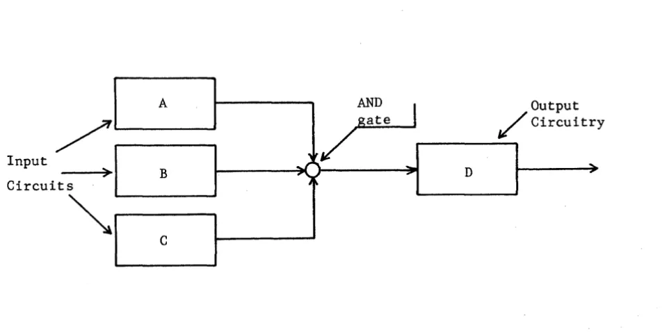
THE AND GATE
Study the block diagram shown in Figure 5-1. the AND circuit from three separate circuits. on a logic diagram by a small, open circle.)
Input
Circuit S
>
~
A
B
C
r
ate ,ItoJ':
...
....
",
,. hNote that there are inputs to (The AND circuit is represented
Output / Circuitr y
D ....
-Figure 5-1. Block Diagram of an AND Gate.
If anyone (or more) of three inputs (A, B or C) is
"0",
the output of the AND gate will be"0".
Only if A ="1",
B ="1",
and C ="1",
will theinput to D be
"1".
The simple electrical circuit analysis (Figure 5-2) denotes that the switch contacts A AND B AND C must be closed to light the lamp. A AND B AND C may be expressed as A·B·C, ABC. or (A) (B) (C) but the brief form (ABC~s normally used.
[image:26.615.35.515.234.473.2]BATTERY
Figure 5-2. Switches Depicting AND Relationship_
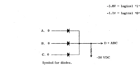
AND gates are logical elements of the computer that perform a logical function by accepting inputs and giving new logical outputs. This is accomplished electrically by the use of components called diodes. The AND gate requires all of its inputs to be logical ones before its output becomes a "1". Any other combination of inputs will result in a logical "0" output. Study the diagram (Figure 5-3) that follows:
Assume that -5.8V
=
logical "1 n-l.lV = logical non
A. 0
B. 0 ---.t---..---.--~ D
=
ABCc.
0-20 VDC
Symbol for diodes.
Figure 5-3. An AND Gate.
Three input signals called A, B, and C are applied to the AND gate. If these are present (ones) simultaneously, there will be a logical "1" out. For example:
ABC
=
1; therefore, D=
1. [image:27.620.67.549.324.578.2]D = logical
"I".
If anyone of the inputs is a logical "0" (A, for instance), the equation. becomes ABC
=
D=
"0" and the output of the AND gate is a logical zero. An AND gate need not be composed of three factors, as any number may be used. Circuit limitations, however, usually set the number of "legs" toapproximately 4 or 5.
Electrically, the AND gate may be approached as follows:
With logical zeros at the input points (-1.1 volts), the diodes are forward biased and conduct. Since the impedence of the diodes in this state is negligible, the voltage at the output is -1.1 volts. If one of the inputs, A for instance, is caused to go to a logical "1" (5.8 volts), the associated diode ceases conduction as it is' back-biased by the input signal. The
diodes associated with inputs Band C, however, are still receiving logical zero (-1.1 volts) inputs and are allowed to conduct. This holds the output to -1.1 volts. (A more complete description of the actual circuitry is found in Chapter VI.)
If all three inputs receive logical one (-5.8 volts) inputs, the diodes cease conduction and the output level goes to -5.8V volts (logical
"I").
In order to receive a logical one output from the AND gate, all three input signals must be logical ones (-5.8 volts each).THE OR GATE
The OR (Figure 5-4) produces a "l" output when at least one of its inputs is a "1". The output of an OR gate is "0" only when all of its inputs are "0". An output circuit with an ORed input is shown in Figure 5-4. (The separate arrows shown entering D represent OR inputs).
INPUT/ CIRCUITS ~
A
B
C
OR
~CIRCUITRY
"
...
:::
D:
,Figure 5-4. Block Diagram of an OR Gate
OUTPUT CIRCUI TRY
....
An OR relationship is available to the boolean variables A and B. Figure 5-5 is an electrical circuit analysis. It is important to note in the analysis that the functions of the boolean variables are electrically
parallel such that if switch A closes or if B closes, or if both close, the lamp lights.
A
BATTERY
B
Figure 5-5. Switches Depicting the Relationship A + B.
This relationship is defined as the OR relationship. It means either one, OR the other, OR both switches are closed. The words lIor bothll denote the condition of the inclusive OR; that is, it includes the case where both are ones. Its counterpart, the exclusive OR, is described later.
E. + 11111
H=E +F+G
F.
~
G. 110 11 +
cut-off
Figure 5-6. An OR Gate.
Therefore, H
or F or G.
E
+
F+
G. This expression is read, the output H equals EElectrically the output H is a "I" when a -5.8 volts is present on the cathode of an input diode. This is caused by the forward bias applied to the diode by the input signal. If all of the inputs are logical zeros
(-1.1 volts), none of the diodes conduct and the output remains at -1.1
volts (logical zero). A more complete description of the actual circuitry can be found in Chapter VI.
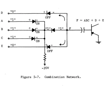
COMBINATION GATES
AND and OR gates may be connected to make the final result a function of many inputs. Figure 5-7 is an example of a combination network. The proof
of the input expression is left to the student.
D
"0"
+"I"
OFF)
A + F = ABC + D + E
ON
~
B"I"
+"I"
FC
"1"
+ ONJ
-:.:E
"0"
[image:30.615.128.467.283.566.2]-20V
Figure 5-7. Combination Network.
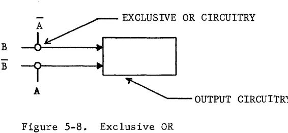
EXCLUSIVE OR
Another logical function is commonly used and plays a very important role in understanding computers. This function is the exclusive OR (symbol ~). The exclusive OR (Figure 5-8) is never implied and must be specifically
indicated by joining the terms with the correct sign.
It should be noted that the exclusive OR differs from the inclusive OR only in so far as it excludes the case 1+1-1, yielding instead 1+1=0
B
B
A
~ EXCLUSIVE OR CIRCUITRY~ ~
I
A
~
OUTPUT CIRCUITRYFigure 5-8. Exclusive OR
The switch analogy for the exclusive OR is illustrated in Figure 5-9.
A B
Battery
o
-A B
Figure 5-9. Switches Depicting the Exclusive OR.
It can be seen that AB or AB would light the lamp but that AB or AB would break both paths between the lamp and !he £attery. The boolean expression for the circuit, therefore, would be AB
+
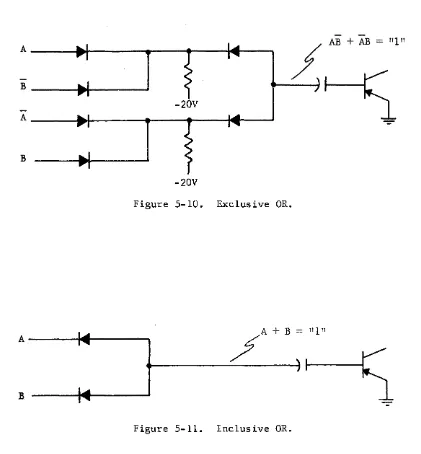
AB. Boolean expressions are always written for a logical one.The actual circuit for the exclusive OR is shown by Figure 5-10. The exclusive OR is a combination network similar to Figure 5-7 whereas the inclusive OR is similar to the circuit illustrated in Figure 5-6.
Compare Figure 5-10 and 5-11.
[image:31.617.224.507.124.255.2]AB
+
AB"1"
AB
-20V A
B
-20V
Figure 5-10. Exclusive OR.
A---~~---~
~A+B
11111
Figure 5-11. Inclusive OR.
[image:32.615.78.499.105.559.2]TABLE 5-1. LOGICAL COMBINATIONS
AND OR Excl. OR
p q p.q p+q P ¥ q
1 1 1 1 0
1 0 0 1 1
0 1 0 1 1
0 0 0 0 0
FUNDAMENTAL RULES OF BOOLEAN ALGEBRA
Boolean Algebra has a set of fundamental rules which allow expressions to be rearranged and simplified. It is frequently necessary to rearrange or
simplify these expressions in order to remove redundancies and make the real relationships easier to understand.
Following is a series of rules which serve as guide lines for the manipulation of Boolean expressions. It is desirable for the student to grasp the
underlying principles in each case rather than to commit the list to memory. Associated problems are included to aid in the application of the
appropriate rule. In Boolean Algebra, as in regular algebra, the key to understanding is practice.
The first 5 statements covered are obvious and serve more as definitions than as rules. These 5, however, are referred to during the discussion of later statements.
STATEMENT 1
A = 0 if A
t
1A = 1 if A
t
0syrmne~ry (balance) between the symbols
"+,,
and and IIAII.II. 1I
,
This could also be stated: If A 1 then A = 0 and if A
o
then A = 1STATEMENT 2
o
r
1 and 1r
0This statement is to clarify the relationship between a logical "1" and a logical 11011 • It is meant to show that the zeros and ones used are
representative of states or conditions (false and true respectively).
STATEMENT 3 0 · 0 0
o
+
0 0This relationship verifies the fact that, regardless of the manner in which a series of zeros are related, the result is zero. This can be
represented by a permanent open (a factor which can never be true) connected in either series or in parallel with another permanent open, resulting in an open. The following diagrams, Figures 5-12 and 5-13, utilize switches to represent these statements.
BATTERY
~O~
_ _-G:O~
Figure 5-12. Switches Representing 0 AND O.
"011
STATEMENT 4 1 • 1 1 1
+
1 1In this case it should be seen that any combination of all ones results in just a single one. In the first case (1 • 1= 1), the analogy can be drawn to a simple straight piece of wire (permanent short) which contains a series of always present logical elements. Assuming that no physical change takes place in the wire, each of its logical components (an infinite number) is equal to a value of 1 (always true or present). Thus a series of lIs ANDed together produces an end result of a single 1 (in this example, the entire wire), as represented by Figure 5-l4A.
To understand the second half of this statement, pieces of wire similar to the one just described (see Figure 5-l4B) with each path being present. either one or the other is all that is necessary redundant and can be removed.
1
+
1 = 1, imagine two connected in parallelIt can be seen that
and that the other path is
BATTERY
r---o~~o----~o~o----~
BATTERYA.
B. Figure 5-14. Switch Equivalence of Statement 4.
STATEMENT 5
o ·
1 0o
+
1 1This statement is actually a combination of statements 3 and 4. The first half can be explained in the same manner as statement 3. Any time one element of a series of elements which are ANDed together is equal to zero, the entire expression must equal zero. The second part can be stated: Any time a group of ORed terms includes a 1, the entire expression is equal to 1 since at
least one of the terms is always present; this fulfills the requirements for satisfying an ORed expression. See Figure 5-15. 0
BATTERY BATTERY
STATEMENT 6
A+A=A
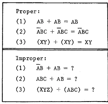
If a Boolean expression exists in this format, statement 6 justifies its reduction to "A". Since, in any given expression, the value A can represent only one condition, it can be seen that ~ore than one A in this case is redundant. Drawing an analogy back to the ball game and equating A with having $10.00, the statement A + A would read "I will go to the ball game if I have $10.00 or if I have $10.00." The redundancy here is obvious. This statement can be used to simplify any expression containing identical ORed terms. As an example, ABC" + ABC
=
ABC. Notice that each ORed term is identical. If they are not completely identical this rule does not apply. The following table shows proper and improper application of this rule.TABLE 5-2. PROPER AND IMPROPER USE OF STATEMENT 6.
Proper:
(1) AB + AB = AB (2) ABC + ABC
=
ABC(3)
(XY)
+
(XY)
=
Xy
Improper:(1) AB
+
AB = ?(2) ABC + AB = ? (3)
(Xyz)
+ (ABC) ? [image:36.615.202.387.373.552.2]BATTERY BATTERY
Figure 5-16. Switch Equivalence of Statement 6.
Work the following problems by indicating if the answer given is true or false. In the area to the right of the problem explain briefly why the rule does not apply to the problems checked false.
T F 1) ABC
+
ABC = ABC T F 2) AC+
AC = ACT F 3) MNS
+
MNS+
MNS = MNST F 4) LPR
+
LPR+
LPR=
LPRThe correct answers to these problems can be found at the end of this chapter. Write, in your own words, a summary of statement 6.
STATEMENT 7 A-A=A
TABLE 4-3_ PROPER AND IMPROPER USE OF STATEMENT 7
Proper
(1) (ABC) • (ABC)
=
ABC (2)(A B C)-(A B C)=A B C
(3 ) (AB ) . (AB ) • (AB ) = ABImproper
( 1 ) (AB)· (ABC) = ? (2)
(A B C) ·
(ABC)=
? (3) (AB)·(A B) .
xy=
?Why are each of the improper statements incorrect?
(1)
(2) (3 )
Using switches, the rule can be demonstrated as in Figure 5-17.
BATTERY
t---o'~o-O ---c'~ ~
- BATTERYFigure 5-17. Switch Equivalence of Statement 7.
T F 5) (XY) (XY) (XY) = XY T F 6)
(AB) (AB) (AB)
=ABT F ... I )
,
(ABC) (CBA) (BCA) = ABCT F 8) A-A ·A=A
Correct answers to the problems may be found at the end of this chapter_ Write, in your own words, an explanation of this rule.
STATEMENT 8 A
+
1=
1This statement is an expansion of statement 4 (second half, 1
+
1 = 1) and can be explained by substituting an A for one of the logical l's instatement 4. Thus statement 4 becomes statement 8.
Statement 4 = 1
+
1 = 1 ;substitute A = A
+
1 = 1 = statement 8.The same reasoning holds true for both statement 4 and 8 since they each involve a term parallel with a permanently closed (non-variable) path. Note that the terms are ORed with each other. This is a prime consideration in both statements. Table 4-4 shows proper and improper use of statement 8.
TABLE 5-4. PROPER AND IMPROPER USE OF STATEMENT 8.
Proper:
(1)
(2)
(3)
ABC
+
1 = 1A
+
1 = 1 A+B+C+1 Improper:ABC • 1
=f
11
(in this case, ABC is one term which is ORed with a logical one).
(1)
(2) ABC • 1 + ABC
=f
1The electrical circuit equivalent to statement 8 is shown in Figure 5-18.
BATTERY BATTERY
A
Figure 5-18. Switch Equivalent, Statement 8.
Work the following problems by checking each answer either true or false. If the answer is' false, explain the reason in the area to the right of the
problem
Answers to these problems can be found at the end of this chapter.
T F 9) A
+
ABC+
DE+
1 1T F 10) B + 1 + C 1
T F 11) ABC
+
DEF+
1+
xyzT F 12) ABCl
+
DEF = 1In your own words write a summary of this rule.
STATEMENT 9
A • 0 = 0
This statement is an expansion of statement 3 (0 • 0 A has replaced one zero.
1
Statement 3
=
0 • 0=
0Substitute A = A • 0 = 0 statement 9
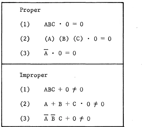
Table 4-5 shows the proper and improper use of statement 9.
TABLE 5-5. PROPER AND IMPROPER USE OF STATEMENT 9.
Proper
(1) ABC· 0 = 0
(2) (A) (B) (C) . 0
=
0(3) A· 0
=
0Improper
(1) ABC
+
0f
0(2) A
+
B+
C • 0f
0(3) ABC
+
0f
0Why
are each of the improper uses incorrect?(1)
(2) (3)
[image:41.613.225.463.221.433.2]BATTERY BATTERY
Figure 5-19. Switch Equivalence of Statement 9.
Work the following problems by indicating if the answer given is true or false. In the area to the right of the problem, explain the reason why each answer checked false is incorrect.
T F 13) wxyz • 0
=
0T F 14) (A) (B)
(6)
(0) = 0 T F 15) (A+
B+
C) • (0)o
T F 16) (A+
A) • (0)=
0You know where to find the answers. In your own words write a summary of this rule.
STATEMENT 10
A
+
0=
AA
BATTERY BATTERY
t----~~
L...-_ _ _ _ --I
o
Figure 5-20. Switch Equivalence of Statement 10.
Note that in the right hand side of the diagram, A can be considered to be ORed with an infinite number of permanent opens (or zeros).
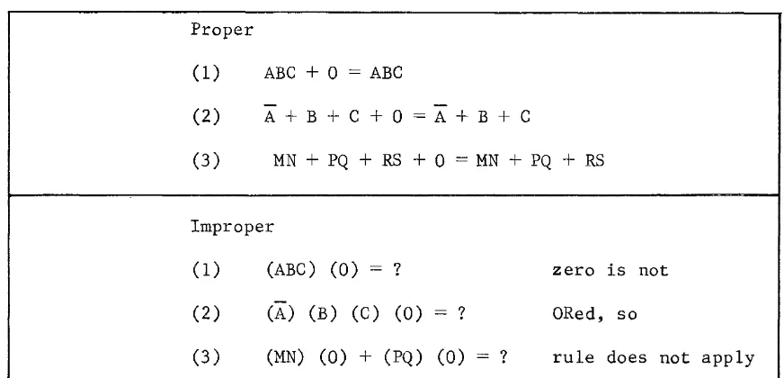
The proper and improper uses of statement 10 are shown in Table 5-6.
TABLE 5-6. PROPER AND IMPROPER USE OF STATEMENT 10.
Proper
(1) ABC
+
a
=
ABC(2) A + B + C +
a
=
A + B + C(3) MN + PQ + RS +
a
= MN + PQ + RSImproper
(1)
(2) (3 )
(ABC) (0) = ?
(A)
(B) (C) (0)
=
?(MN) (0) + (PQ) (0)
zero is not ORed, so
? rule does not apply
[image:43.615.106.542.106.194.2] [image:43.615.93.529.378.588.2]T F 17 ) xyz
+
0 = xyz T F 18) ABCO=
ABCT F 19) AB
+
RS+
xy+
0 = ABT F 20) (zm) (0) (RS)
=
(ZM) (RS)In your own words write an explanation of rule 10.
STATEMENT 11
A • 1 = A
This statement is a variation of statement 7 which states A • A
=
A. In statement 11, the value 1 has been substituted for one of the A's. A common-sense explanation shows that any single A is connected in series with an infinite number of constant logical ones. These would be the segments of the wire that make up the circuitry. This rule justifies the simplification of any expression containi.ng ANDed terms, some of which are equal to 1. TheselIs are redundant terms and can be removed without altering the effect of the resulting expression (or circuitry). The electrical circuit equivalent for statement 11 is shown in Figure 5-21.
BATTERY BATTERY
Figure 5-21. Switch Equivalence of Statement 11.
Why or why not?
The proper and improper application of statement 11 is shown in Table 5-7.
TABLE 5-7. PROPER AND IMPROPER USE OF STATEMENT 11.
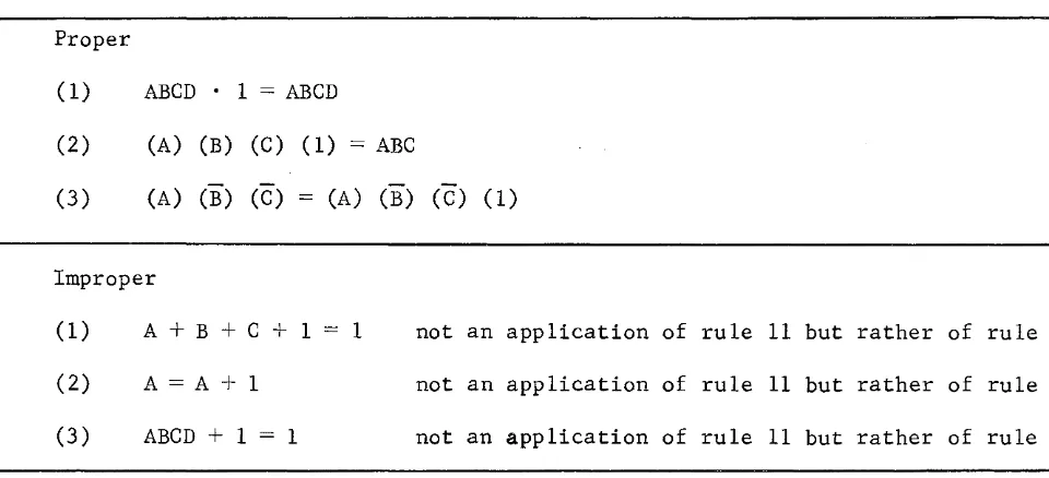
Proper
(1) ABCD· 1 = ABCD
(2) (A) (B) (C) (1) = ABC
(3)
(A)
(~) (~) =(A)
(~) (~)(1)
Improper
(1)
(2) (3 )
A+B+C+1
A = A
+
1 ABCD + 1=
11 not an application of rule 11 but rather of rule fr. not an application of rule 11 but rather of rule 8. not an application of rule 11 but rather of rule 8.
Work the following problems by indicating if the answers given are true or false. In the area to the right of the problem explain why problems marked false are incorrect. If you mark the statement true, list the statement number that validates it (if other than statement 11).
T F
T F
21) 22)
ABC = (A) (1) (B) (C)
[image:45.615.98.578.321.540.2]T F 23) (AB) (CD) (1) = (AB) (CD)
T F 24) (AB) (xy) (CD)
=
(1) (AB) (1) (xy) (1) (CD)In your own words, write a summary of this rule.
STATEMENT 12
A
+
A=
1The main characteristic to recognize when applying this statement is that it deals with a term ORed with its complement (opposite). In addition, statement 12 is a direct result of applying two previously-covered rules. These two are:
Statement 1: if X
=
0 then X=
1 Statement 5:o
+
1=
1By evaluating statement 12 in view_of statement 1 it can be seen that under any set of conditions either A or A must be equal_to a "1". It can also be seen that when A is equal to 1, the condition of A must be equal to zero and vice-verse. If it is assumed that A
=
1, thenA =
0 (written 1+
0); or if it is assumed that A=
0, thenA
=
1 (written 0+
1). Each of these are equal to "1" by statement 5. By substitution, A+
A
=
1, where (A+
A)
bears the relationship of (1+
0) or 0+
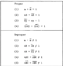
1).TABLE 5-8. PROPER AND IMPROPER APPLICATIONS OF STATEMENT 12.
Proper
(1) m+m= 1
(2) AB+AB= 1
(3) xy + xy = 1
(4) (~d) + (~d) 1
Improper
(1) m -m=f= 1
(2) AB + AB =f= 1
(3) AB + xy =f= 1
(4) ABC + ABC =f= 1
(5) ABC + ABC =f= 1
Why are the improper statements in the table incorrect?
Work the following problems by indicating if the answers given are true or false. In the space to the right of the problem explain why each false answer is incorrect.
T F
T F T F T F
25) 26) 27) 28)
ABC + ABC = 1
(ABC + DEF) + (ABC + DEF) 1
[image:47.615.195.463.118.401.2]In your own words, write a summary of this rule.
STATEMENT 13 A·A=O
This statement can best be explained by referring to two previous1y-covere~ rules, statement 1 and statement 5. Statement 1 states: if X = 0 then X 1. Statement 5 states: 1 • 0 =
o.
Statement 1 shows that comp1ementa!J termscan never be equal to each other. Therefore, the values for (A • A) must assume either of the following formats (1 . 0) or 0 • 1). In either case the problem can be further resolved by invoking statement 5, since these formats fit its characteristics. By referring to statement 5 the entire expression is seen to equal zero. The following is a step-by-step outline of the above process.
Statement 13 A • A
o
Substitution (0.1)
o
or (1 • 0)o
Statement 5 (0) + (0)=
0Statement 3 0=0
Themain characteristic to look for when applying statement 13 is a factor to be ANDed with its complement. The number of factors included is immaterial so
long as factors are complementary and are ANDed together.
TABLE 5-9. PROPER AND IMPROPER USE OF STATEMENT 13.
Proper
(1) A • A = 0 (2) AB • AB = 0 (3) AB • AB = 0
Improper
(1) A+A=j=O
-
-(2) AB • A B =j= 0 (3) ABC • AB =j= 0
Why are the improper statements incorrect?
Solve the following problems by indicating if the answers are true or false. In the area to the right of the problems marked false, explain why they are incorrect.
T F (29) AB
.
AB = 0T F (30) (xAB)
·
(ABx) = 0 T F (31) (x+B)·
(B+x) = 0 [image:49.612.188.375.118.331.2]STATEMENT 14
=
A=A
- This statement is design~d for cases which include double negatives. This statement may read "not A
=
A". An analogy can be drawn to the use of double negatives in English. A person corrected for saying "I don't have no money" would be told that the double negative is the same as no negative at all; it is the same as saying "I do have money". Another example would be to turn a playing card, which is lying on the table, over once for each negation. The result would be the card returning to the same state in which it started.Both of these analogies are true for statement 14. If A is not present then A must be present. Thus
X
=
A.This statement applies to a term of any length and consisting of any internal method of grouping so long as both negation bars cover the entire term.
Table 5-10 exemplifies the proper and improper usage of statement 14.
TABLE 5-10. PROPER AND IMPROPER USE OF STATEMENT 14.
Proper
(1) AB
=
AB(2) MN = MN (notice that the negation over N has not been disturbed).
(3) AB
+
c=
AB+
cImproper
(1) AB =t- AB
(2) A
+
BC =t- A+
BC [image:50.615.61.539.356.662.2]Work the following problems by indicating if the answers given are true or false. In the area to the right of each problem marked false, explain why the given answer is incorrect.
T F 33) ( A + B + C ) = A + B C
T F 34) A+B+C=A+B+C
T F 35) A+B=A+B
=
=
T F 36) A+B=A+B
Check your answers. In your own words, write a summary of this rule.
Before continuing to the remaining statements, work the following problems as a review.
Use only the rules covered thus far and reduce each expression as far as possible. Some problems may require the application of more than one rule to reduce it to its simplest form. Check your answers.
REVIEW QUESTIONS
37)
o ·
0 38) I + 1 39) I · I 40) 1 + 0 41) 0 + 043) A • 0
=
44) 1 • A =
45) 0
+
146)
o
147) A
+
1 =48) 0
+
A=
49) (A
+
B+
CD) • 0=
50) AB + AB =51) A
+
AA=
52) AB
+
BA+
AA =53) AA + A + A + A + 1 =
54) A + B + A + B + B
55) AB + AB + AB + AB + AB =
56) AB
+
CD=
57) (C+L) (C • 1) + (0 · A) (1 + A)
If correct answers were not obtained for all of the review problems, the pages relating to the corresponding type problem should be reread and the problem retried.
STATEMENT 15
A+AB=A
This statement is applied to simplify a type of expression in which the terms are not altogether cornmon. The major important characteristics in this
format are: 1) The expression must contain ORed terms (in this case A ORed with AB) and 2) There must be a factor which is common to all terms involved (in this case the factor A appears in each of the ORed terms). To explain this statement, each condition of A is assumed and a logical
Assume the value of A is 1 (A is true).
Original statement: A+AB=A
Then by substitution 1 + 1
.
B = 1(placing lIs for A IS),
By applying statement 11, 1 + B 1 By applying statement 8, 1 = 1
Thus, when the condition for A is true the equation is true.
Assume the value of A is 0 (A is not true).
Original statement: A+AB=A
By Substitution for A, 0+0 · B
o
Applying statement 9, 0+0
o
Applying statement 3,
o o
Thus, when the condition for A is false the entire equation is false.
Summarizing these two conclusions, it can be seen that the resulting truth of this expression has no dependence on the variable B but is directly dependent on the state of variable A.
The result can be verified by evaluating the electrical equivalence of the expression as shown in Figure 5-22.
A
BATTERY BATTERY
I
~A
~ ~rnI=
L..-_ _ _ _ ---I
A
0-0
--~~o---'
Figure 5-22. Switch Equivalence of A + AB = A
and the term AB is redundant.
In the format of statement 15, a single term may contain more than one variable as long as all the variables in one ORed term appear in the other.
Example
Original Statement: A+AB=A
Substitute xyz for A: xyz
+
xyzB=
xyz. Substitute 1m for B: xyz+
xyzlm = xyz.This final expression, xyz
+
xyzlm for statement 15.xyz, fulfills the format requirements
Table 5-11 shows expressions simplified by statement 15. It also shows formats which are commonly mistaken as being properly reduced entirely with statement 15.
TABLE 5-11. PROPER AND IMPROPER FORMAT FOR STATEMENT 15
Correct format and application of statement 15. (1) C
+
CD = C(2) ABC
+
ABCDEF = ABC (3) (ABC)+
(ABC) (DEF)(4) AB + ABC
+
DEF = AB+
DEFIncorrect format - cannot be ·resolved by statement 15 alone.
(1) AB
+
ACD(2) AB
+
ABD(Both variables in the left hand term do not appear in the right hand term).
[image:54.613.72.546.343.675.2]Solve the following problems by indicating if the answer given is true or false. In the space to the right of the problems marked false explain why these problems are incorrect.
T T T T
STATEMENT 16
A(B
+
C)=
AB+
ACF
F
F
F
(58) (59) (60) (61)
ABDEF
+
DE = DE A B+
ABC=
AB(AB)
+
C+
DE (AB)+
C (AB)+
C F 310 F220+
F400 F3l0 F220 F3l0 F220This statement is most often used to manipulate already existing expressions. It does not actually eliminate any redundancies, but allows an expression to be written into a form for grouping with other terms. Quite often this grouping will allow reduction via another statement.
The electrical equivalence of this rule, Figure 5-23, shows that in order for the bulb to light, switch A must be closed (A present or true) along with either switch B or switch C.
BATTERY
~A
BATTERY
I
.
' - -_ _ _ _ ....J
Figure 5-23. Switch Equivalence of Statement 16.
The switches labeled A in the right-hand diagram are joined since they must be operated together. This is dictated by the fact that in a boolean
expression any given letter can stand for only one variable; thus, all
terms labeled A, for example, must be in the same state (all true or all false) at a given time.
ExamEle 1
Initial expression to be simplified: A(B + C) + AB = ? Apply statement 16 to left-hand term: AB + AC + AB
Apply statement 6: AB + AC
Apply statement 16 in reverse: A(B + C)
The last step in the example could have been omitted, if desired, since either format is acceptable.
This brief, simple example points out the use of statement 16 in that, what was not an apparent application of statement 6 became obvious after
the original expression was expanded. Furthermore, in its original grouping, the variables within the term A(B + C) could not have been used separately to simplify other areas of a longer expression. Consider the following example.
ExamEle 2
Expression to be simplified: A (BC + DE) + B + ADE
Statement 16 : ABC + ADE + B + AD E
Statement lY. ADE + B + ADE
Statement 12: 1
+
BStatement 8: 1
Here the final form of the original expression is 1. In its original format, without expanding the term A(BC + DE), it is not apparent that reduction would result. However, upon expanding this single term, it is obvious that the expression was not in its simplest form.
Work the following problems indicating if the answer given is true or fa lse. To the right of the problems marked as false, explain why each is not a correct statement.
T F (62) A(A + B) =AA+AB T F (63) AB (D + E) = ABD + E T F (64) AB(BC + BD) = ABBe + ABBD
IT'
...
(65) A (13 [
A13C) = A 13 .[
T F 66) ABCD + ADEF = AD (BC + EF)
By circling the number, indicate which of the problems just completed can be further simplified. Check to see if you are correct. For practice, perform these simplifications applying all the rules covered to this point.
STATEMENT 17 A+AB=A+B
This statement allows the removal of a redundant term through use of
statement 1. Investigation of the format should reveal that it consists of a single term (A in this case) ORed with its complement which is ANDed with one or more other variables. This is illustrated below.
A+~
/
f<--_
Second term consisting of the
complement of the first term
(A
in this case) AND one or more other variables (B in this case)Single term
ORed with second term
Other examples of the correct format are: AB + (AB) C = AB + C
A+AB=A+B A C + ACD = AC + D
The student should be sure that the correct format is understood before proceeding. As practice, indicate which of the following problems are in the correct format for applying statement 17. Check your answers.
The explanation of this rule can most easily be seen by reviewing the electrical circuit equivalent given in Figure 5-24.
A
BATTERY BATTERY
Figure 5-24. Switch Equivalence of Statement 17.
From the circuits, it can be seen that closing switch A (making condition A true) lights the lamp in either case. If the top path were open (switch A open or A = 0) then, by statement 1, the presence of (switch
A
closed ORA
= 1) is ensured. Therefore, in absence of the top path, the only variable whose state has to be determined is B. It is unnecessary to restate (include) the switchA
since it has already been established that it closes if switch A is open.This rule, in addition to removing redundant terms, also assists in
making clear a long expression which does not appear as if it can be readily simplified. The following example illustrates this point.
Example
Original expression: A + AB + BCD Applying statement 17: A
+
B + BCD Applying statement 15: A+
BIn the example, eliminating the redundant A (using statement 17) made it obvious that the entire term BCD was redundant by statement 15. Thus, the application of statement 17, in addition to removing a redundant term, has made further reduction more obvious.
Also notice in the example that statement 17 applies even though there is an added term BCD. This can be done as long as any additional terms are ORed.
T F 67) x+Ax=x+A
T F 68) Ax+Axy=Ax+y
T F 69) AB + ABx = AB + x
T F 70) AB + xy + AB CD = AB + CD + xy
STATEMENT 18
A + B = A B; AB = A + B
This statement is made up of two distinct parts. For identification purposes they are referred to as follows:
Part 1: A+B=AB
Part 2: AB = A + B
The need for this rule arises from the desire to break down entirely negated expressions into individual terms. The purpose of this is to facilitate additional simplification by allowing these new terms to be combined with other terms in the entire expression through the use of previous rules. As an illustration refer to the following example.
Exam,ele 1
1) B+D+E + (BCD)
2) B + D + E +B+C+D 3) B + D + E + B + C 4) 1 + D + E + C
5) 1
In example 1, the original expressio~ (1) shows no apparent rearrangements; however, since the terms under the negation bar are similar to those outside the negation, breaking down of this term may be expected to yield additional simplification. The term under the bar is read "not the quantity BCD" and the factors within this term cannot be used individually until the
negation bar is broken. By applying statement 18, part 2, expression (2) is obtained. Here the bar has been broken and the individual factors can be grouped with other terms. Expression (3) is arrived at by applying
stat~ent 6 to eliminate the redundant
D.
In expression (4), the valuesthe result equals 1 by statement 8.
The development of statement 18 was accomplished by a man named De Morgan and in his honor, statement 18 is sometimes called De Morgan's Theorem. This theorem is explained by breaking each part into two sections. The
first includes a logical explanation; the second discusses the mechanical operations necessary to perform the conversions.
Part 1
Inspection of the first part of statement 18 (A
+
B=
A B)
shows that it is read "not the quantity A OR B." If "the quantity" is not present itmeans that both A and B are not present. Ihis is concluded from the definition of OR, which reads "the quantity is true if A OR B is true". Since the quantity is not true, implied by the negation bar over the entire quantity, neither of the variables is true. Thus (A
+
B) =A B.
Notice that the final expression is the AND function of each of the variables and that each of the variables has been negated. It is important to note that (AB) and(A B)
are not equal to each other.To mechanically perform the operation, the following statement is used: To break the negation bar which combines several ORed terms, change each OR sign to the AND sign and negate the individual variables, for example:
(A
+
B+
C) =A· B· C~
l
Negatechange OR's
individual terms
to AND's
Additional Examples of Statement 18, Part 1:
1)
2)
3)
4)
(A
+
B+
C+
D) =A . B . C .
D (A+
B+
C)+
D =(A .
B •C)
+
DNotice that the term D is not affected as it is not included under the negation.
(A
+
B+
C) = A • B • C • = A • B • CIn this case following the rule and negating each factor causes variable A to be negated twice. Statement 14 allows this to be simplified to A.