TITLE
GAIT PATTERN DETECTION FOR AMPUTATED PROSTHETIC USING FUZZY ALGORITHM
AHMAD FAISAL BIN ABDULLAH
A project report submitted in partial fulfillment of the requirement for the award of the
Master of Electrical Engineering
Faculty of Electrical and Electronic Engineering Universiti Tun Hussein Onn Malaysia
ABSTRACT
ABSTRAK
Kaedah rawatan pemulihan konvensional bagi gaya berjalan (gait) tidak memberikan
maklumat secara kuantitatif dan grafik pada kinematik gait yang tidak normal dan
kaedah ini hanya sesuai diamalkan secara klinikal serta bergantung kepada
pengalaman dan kepakaran ahli terapi. Pesakit kudung dengan kaki palsu (prostetik)
mempunyai sisihan (berubah) gaya berjalan disebabkan oleh pelbagai factor
kebiasaanya keselarian prostetik dan masalah ketidaksuaian kaki palsu. Analisis gaya
berjalan menggunakan penderia (sensor) sangat meluas kepenggunaannya dalam
memberikan maklumat yang berguna untuk pelbagai aplikasi yang berkaitan dengan
kesihatan kerana cara ini murah, mudah, dan berkesan. Projek ini memberi tumpuan
kepada membangunkan sistem untuk mengukur sudut sendi manusia bahagian bawah
abdomen khususnya sendi peha (hip), lutut (knee) dan buku lali (ankle) kemudian
menggabungkan algorithma pintar dalam mengesan fasa-fasa gait. Prototaip yang
dibangunkan mempunyai tiga penderia Inertial Measurement Unit( IMU ) untuk
mengukur dan mengenalpasti gaya berjalan yang dipasang pada posisi specifik.
Data-data dari penderia akan dan diproses dalam Arduino dan MATLAB melalui
komunikasi serial untuk mendapatkan paten berjalan (trajektori). IMU menyediakan
orientasi sudut anjakan semasa berjalan kemudian paten berjalan ini dipaparkan
secara grafik melalui GUI MATLAB .Fuzzy Inference System( FIS ) digunapakai
untuk meningkatkan ketepatan pengesanan fasa gaya berjalan dari trajektori gaya
berjalan diperolehi. Keberkesanan prototaip dan sistem FIS yang memuaskan serta
mempunyai potensi untuk dijadikan alat untuk mendiagnosis dan meramalkan kadar
penyakit dan system maklumbalas dalam membantu proses pemulihan pesakit
CONTENTS
TITLE i
DECLARATION ii
DEDICATION iii
ACKNOWLEDGEMENT iv
ABSTRACT v
ABSTRAK vi
CONTENTS vii
LIST OF TABLES x
LIST OF FIGURES xi
LIST OF SYMBOLS AND ABBREVIATIONS xiii
LIST OF APPENDICES xiv
CHAPTER 1 INTRODUCTION 1
1.1 Research Background 1
1.2 Problem Statement 2
1.3 Aim and Objectives 2
1.4 Scope of Project 3
1.5 Outline of the Thesis 3
CHAPTER 2 REVIEW ON GAIT PATTERN REHABILITATION 4
2.1 Introduction 4
2.3 Gait and Biomechanics 5
2.3.1 Gait Cycle and Biomechanics of Walking 5
2.3.2 Joint Angle Trajectory 7
2.4 Gait Analysis for Amputated Prosthetics 8
2.4.1 Principle of Prostheses Examine 9
2.4.2 Prostheses Rehabilitation 10
2.5 Previous Work 10
CHAPTER 3 METHODOLOGY 13
3.1 Introduction 13
3.2 System Architecture 13
3.3 Hardware Implementation 16
3.3.1 Power Supply 16
3.3.2 Arduino Microcontroller 16
3.3.3 IMU sensor (MPU 6050) 17
3.4 Software Implementation 18
3.4.1 Arduino 18
3.4.2 MATLAB Graphical User Interface (GUI) 21
3.4.3 Fuzzy Logic Toolbox 22
3.5 Sensor Placements and Experimental Setup 22
3.6 Angle Measurement using Wearable Sensors 24
CHAPTER 4 RESULTS AND DISCUSSION 27
4.1 Introduction 27
4.2 GUI Performance 28
4.3 Arduino Serial Monitor Output Data 29
4.4 Data Record and Validation 29
4.6.1 Thigh (Hip) Gait Trajectory 33
4.6.2 Shank (Knee) Gait Trajectory 34
4.6.3 Foot (Ankle) Gait Trajectory 36
4.7 Gait Pattern Performance 37
4.8 Fuzzy Gait Phase Detection Algorithm 40
4.8.1 Joint Angle Phase 40
4.8.2 Fuzzy Membership Function and Pre-defined Rules 41
4.8.3 Fuzzification 42
4.8.4 Defuzzification 44
4.9 Future Development on Prosthetic Fitting Abnormal Gait 47
4.10 Discussion 48
CHAPTER 5 CONCLUSION 50
5.1 Conclusion 50
5.2 Recommendation 51
REFERENCES 52
LIST OF TABLES
2.1 Summary of motion positions on hip joint, knee joint and ankle joint 7
4.1 Measurement for angle accuracy 30
4.2 Parameter for Membership Function Inputs 41
4.3 Pre-defined rules set for gait phase 41
LIST OF FIGURES
2.1 A normal gait cycle and its phases 6
2.2 A measurement of angular displacements of the lower extremity 8
3.1 Flowchart of work 14
3.2 A complete system architecture 15
3.3 Arduino Uno Microcontroller 16
3.4 Diagram of MPU6050 type of GY-521 breakout board connection
with Arduino 17
3.5 CD74HC4067 Multiplexer 18
3.6 Flowchart process of angle measurement system in Arduino 20 3.7 The placement of IMU sensors on the lower part of body segment 23
3.8 A pathway lane for recording walking gait 24
3.9 Projection of z-axis acceleration on x-axis tilt 26
4.1 GUI MATLAB visualization 28
4.2 Serial Monitor status for successful calibration 29
4.3 A test setup to set angle using Protractor 30
4.4 Difference between IMU raw signal and signal filtered using Kalman 31 4.5 Sample of ankle angular displacement trajectory in walking condition
for 5 second of recording 32
4.6 Reference thigh trajectory for (a) measurement along x-axis,
(b)measurement along y-axis 33
4.7 Reference shank trajectory for (a) measurement along x-axis,
(b)measurement along y-axis 35
4.8 Reference ankle trajectory for (a) measurement along x-axis,
(b)measurement along y-axis 36
4.9 Comparison gait pattern for two subjects at position (a) thigh,
(b)shank, and (c) foot 39
4.11 Fuzzy model developed to identify the phases 42 4.12 The classifying the various ranges of hip, knee and ankle joint angle 43 4.13 Classifying the various stages of output Gait Phase (Defuzzification) 44
4.14 Rules created for gait phase 44
4.15 Rules viewer of gait phase detection 45
4.16 Simulation of FIS system using Simulink 46
LIST OF SYMBOLS AND ABBREVIATIONS
FIS - Fuzzy Inference System FLC - Fuzzy Logic Control GUI - Graphical User Interface IMU - Inertial Measurement Unit MF - Membership Function LR - Loading Response MSt - Mid Stance
LIST OF APPENDICES
APPENDIX TITLE PAGE
A Data Sampling 55
B Arduino Coding Programming 56
CHAPTER 1
INTRODUCTION
1
1.1 Research Background
Amputation is the surgical removal of all or part of a limb or extremity. There are many reasons for amputation including poor circulation because of damage of the blood arteries called peripheral arterial disease. The other causes for amputation are severe injury (trauma), cancerous tumour in the bone or muscle of the limb, thickening of nerve tissue (neuroma) and frostbite. Amputee need undergoes for long-term recovery and rehabilitation including use of artificial limbs or called prosthesis[1]. Due to the increasing rate of amputations, there is an ever-growing demand for prosthetic limbs [2].
1.2 Problem Statement
Gait analysis is useful method to evaluate amputee condition especially to monitor the rate of rehabilitation and the therapy effectiveness. The gait parameters are interrelated with amputees gait pattern. Somehow prosthetic fitting is a factor that effect on gait of amputees [4].The most common cause of an abnormal gait pattern in amputees is inadequate prosthetic alignment. The angular and translational position of the socket in relation to the pylon and foot is an important determinant of the walking pattern [5].There are conventional method to evaluate gait pattern of amputees by visual observation and quantitative measurement system. Then the result compared with the gait pattern predicted from biomechanical analysis. Somehow visual observation was found to be an unreliable clinical skills because gait parameters such step length and step size difficult to assess visually[6].
In particular, a review studies by Rietman, Postema and Geertzen (2002) reported that instrumented gait analysis in prosthetics provides better insights and knowledge of the different adaptive mechanisms of the body in walking with prosthesis. Importantly, new prosthetic components must test to investigate whether they improve the gait of the amputee wearing the prosthesis. Gait analysis in prosthetics allows determines abnormalities on amputees gait pattern and tried to adapt different strategies to let them walk as normally as possible with prosthesis [7]. There are several problems in existing gait analysers. Firstly, the low mobility problem, current gait analysers such as those using image processing need large equipment. Secondly, the cost of gait analysers are high due to the construction and operation cost.[8]
1.3 Aim and Objectives
The aim of this project is to detect a gait deviation or abnormal gait patterns that arise from fitting of lower extremity amputated prosthetic. Therefore, based on underlined problem statement, the objectives are outlined as follows.
a. To investigate on existing measurement system to acquire gait trajectories. b. To implement gait pattern detection using intelligent algorithm
This project development is focused on patient who suffered for amputation with prosthetic fitting on lower extremity body. A consideration of joint parameters will be implementing in this proposed method to detect their gait patterns. The complete system contains appropriate hardware selection comprising of three inertial sensors that attach on proper identified closed-joint which are thigh (hip), shank (knee) and foot (ankle). Then a data acquisition device is used to acquire hip, knee and ankle joint angular displacement during walking. Pre-processing through microcontroller is to acquire joints angle and post processing via MATLAB selected to visualize gait trajectories and pattern detection. Software application is used to identify the gait detection by mapping to a pre-defined set of fuzzy rules in Fuzzy Logic toolbox that available in MATLAB. The output of the Fuzzy Inference System (FIS) is the gait phase detected for a given instance of time. Experiments will carry out to validate the feasibility of the algorithm with the acquisition of the joint parameters for several gait cycles. A graphical user interface (GUI) will developed for data acquisition to represent angle of interest joints and gait pattern detection.
1.5 Outline of the Thesis
CHAPTER 2
REVIEW ON GAIT PATTERN REHABILITATION
2
2.1 Introduction
Gait analysis is the study of the pattern of human locomotion, which is carried out by visual observation, sensor technology, video/optical cameras or integration of these technologies. Gait analysis is widely applied for gait rehabilitation, sports performance analysis, post injury assessments and sports product design. Recently, researchers are preferable performing a gait analysis using sensor application due to some constraints using others techniques such higher cost and time and space consumption. In order to monitor and analyse the gait of human, it is necessary to identify and understand the movements (kinematics) of humans and the forces and torques (kinetics) that are applied on the human joints. Currently, there are many sensor technologies available in the current industry to acquire accurate detection of gait parameters, which determine gait pattern, such as accelerometers, gyroscopes, foot switches, load cells, electromyography (EMG) sensors and etc[9].
In prostheses discipline, prosthetic staffs must completely understanding a human anatomy terminologies in order to examine any issues arise from body alignment problems that related to wearable prostheses. The major joints of the lower limb are sacro-iliac joint, hip joint, knee joint and ankle joint. These joint are relatively unmoveable.
Hip joint is the junction between the pelvis and the thigh. It should be move in all direction of all planes and can move in circular rotation around the socket axis or called ‘circumduction’ movement. A simple hinge or knee joint is the junction
between thigh bone and the leg. It has one plane movement only which is move from the straight extended position into flexed position. The lowest joint and most complex joint movement that located between the leg and foot is the ankle joint. It has tri-plantar movement.
2.3 Gait and Biomechanics
Normal gait has been described as a series of rhythmical, alternating movements of the limbs and trunk which results in the forward progression of the centre of gravity. Normal human gait should understand comprehensively before evaluating gait in prosthetic rehabilitation. The centre of gravity is the representative point on the body on which the force of gravity acts. This is generally found to be in the midline of the body lying slightly anterior to the second sacral vertebra. Human gait is usually described in terms of the various components of the gait cycle.[10]
2.3.1 Gait Cycle and Biomechanics of Walking
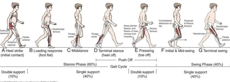
Figure 2.1: A normal gait cycle and its phases.
Analysis of the human walking pattern by phases more directly identifies the functional significance of the different motions generated at the individual joints and segments [11].
i. Initial Contact –is the moment when the foot touches the floor. The joint postures presented at this time determine the limb’s loading response pattern.
ii. Loading Response –is the initial double-stance period. The phase begins with initial floor contact and continues until the other foot is lifted for swing. Using the heel as a rocker, the knee is flexed for shock absorption. Ankle plantar flexion limits the heel rocker through forefoot contact with the floor. iii. Mid-Stance– is the first half of the single-limb support interval. In this phase,
the limb advances over the stationary foot through ankle dorsi-flexion (ankle rocker), while the knee and hip extend. Mid-stance begins when the other foot is lifted and continues until body weight is aligned over the forefoot. iv. Terminal Stance –is completes the single-limb support. The stance begins
with the heel rising and continues until the other foot strikes the ground, in which the heel rises and the limb advances over the forefoot rocker. Throughout this phase, body weight moves ahead of the forefoot.
v. Pre-Swing –is the second double-stance interval in the gait cycle. Pre-swing begins with the initial contact of the opposite limb and ends with the lateral toe-off. The objective of this phase is to position the limb for swing.
forward and the tibia is vertical (i.e., hip and keen flexion postures are equal). The knee is allowed to extend in response to gravity, while the ankle continues dorsi-flexion to neural.
viii. Terminal Swing – is final phase of swing begins with a vertical tibia and ends when the foot strikes the floor. Limb advancement is completed as the leg (shank) moves ahead of the thigh. In this phase, limb advancement is completed through knee extension. The hip maintains its earlier flexion and the ankle remains dorsi-flexed to neural.
[image:18.595.105.533.358.554.2]A position angle of joint motion on hip, knee and ankle joint during normal walking gait phase is highlight in Table 2.1.
Table 2.1: Summary of motion positions on hip joint, knee joint and ankle joint[12].
Position Hip Joint Knee Joint Ankle Joint
Heel Strike 25° flexion 5° flexion 5° plantar-flexion Foot Flat 25° flexion 15° flexion 10° plantar-flexion Mid Stance 10° flexion 10° flexion 5° dorsi-flexion
Heel Off 13° Extension 2° flexion 15° dorsi-flexion Toe Off 10° Extension 40° flexion 20° plantar-flexion Acceleration 10° flexion 40° flexion 20° plantar-flexion
Mid Swing 20° flexion 60° flexion Neutral
Deceleration 25° flexion Flexion - extension Neutral
2.3.2 Joint Angle Trajectory
Figure 2.2: A measurement of angular displacements of the lower extremity [11].
As a basis of gait kinematics, kinematic measurement is the essential principle that can significantly affect the selection of the kinematic analysis method. Two main techniques are employed in the kinematic measurement of the human gait. One earlier developed technique is based on camera systems, which are used in a large number of specialized laboratories. The other technique for kinematic measurement is the use of wearable sensors [11]. Kinematic measurement could obtained through placement of three IMU sensors attached on the foot, calf and thigh separately such illustrated in Figure 2.5
2.4 Gait Analysis for Amputated Prosthetics
plane motions are best seen from the side, and frontal-plane motions are best seen from the front or rear.
ii) Identification of gait deviations.-The gait deviation is defined as any gait characteristic that differs from the normal pattern. A knowledge of normal locomotion will be useful to compare with deviation occurred.
iii) Determination of causes.- In order to decide a prevention treatment to minimize the deviation, the root of cause should be analyse may come obvious from prosthesis fitting or restricted on amputee range of motion at joints, muscular weakness, excessive fear, or old habit patterns
2.4.1 Principle of Prostheses Examine
The observation of gait begins with a general assessment, noting symmetry and smoothness of movements of the various body parts. The cadence (steps/minute), base width, stride length, arm swing, movement of the trunk, and rise of the body is a gait parameters will observe by therapist. Individual segments of the kinetic chain as the subject ambulates, including the head, shoulders, arms, trunk, pelvis, hips, knees, ankles, and feet will follow checking up.
If amputee feels pain during walking in examination process, it should take consideration as effect on position in the gait cycle. Subjects are acquire to wear a simple shirt then proceed to be viewed from the front (anterior), side, and behind (posterior). The front view is helpful in viewing any deviations of the trunk or pelvis. The side view is helpful in examining exaggerations of spinal motions such hip motion. The posterior view is probably best for observing pelvic abduction or adduction in determining whether there is a Trendelenberg gait [15].
2.4.2 Prostheses Rehabilitation
The main purpose of rehabilitation in prosthetic artificial limb is to reduce instability and to facilitate normal, effective and efficient patterns of gait. It is to prevent from falling and to avoid changes of direction while walking. Gait rehabilitation session is conducted by physical therapist. The estimation on gait parameters such step and stride length, weight shift, trunk alignment, pelvic rotation, reciprocity, symmetry are most important events that needs observation. Therapist spotted the dysfunction on gait parameters then determines an appropriate a correction to improve the performance of prosthetic on patient [17].
However, this clinical gait rehabilitation treatment has several weaknesses such:
i) the effect of rehabilitation treatment is dependent on the physical therapist’s knowledge, accuracy of clinical observation and experience
matching the impairments to the appropriate intervention to minimize limitations and disability
ii) effectiveness of the intervention strategy to remediate the impairment is difficult to document objectively, and
iii) The rehabilitation treatment consists of manual, verbal and visual feedback (mirrors and videotapes) while working one on one with a therapist in a health care setting.
2.5 Previous Work
There are six general devices that are currently applied for gait analysis such a footswitch stride analysers, ground reaction force analysers, electrogoniometers, electromyography (EMG), metabolic energy expenditure, and optic sensors. In general these six standard devices are restricted to the confines of a clinical environment [18].
metatarsophalangeal joint, the fourth metatarsophalangeal joint, and the heel. At starter, the author constructs an acceptable range of normal GCF pattern by perform a trial of normal human training to provide fundamental information as reference band in closed loop system. Then, the system provides a normal GCF patterns as visual feedback information for patients to correct their gait by trying to follow the normal GCF pattern. A graphical information GUI provide a data about the degree of gait abnormality based on how far the measured GCFs from the normal GCF bands and change of center of GCF (CoCGF) [17].
A similar method as detection of gait pattern parameters from foot pressure was developed by Pawin (2011) using Force Resistive Sensor (FSR). A continuous improvement has be done by applying a different technique for detecting abnormal gait cycles by estimating the Zero Moment Point (ZMP) locus of each foot that measured from FSRs. ZMP is defined as the point on the ground where the net moment of the inertial and gravity forces has no component along the axes parallel to the ground. The author claimed the reaction at any point under the foot can be represented by a force and moment due to complicated measurement of Ground Reaction Force (GRF) distribution. When plot the ZMP’s position of each step in a gait cycle, the pattern in the plot is called locus of ZMP. The author prefer uses a Multilayer Perceptron (MLP) such Artificial Neural Network were applied to recognition the normal ZMP locus of gait cycle and compare with the walking gait for detect the abnormal gait [19].
tabs which allows user to enter subject information, acquire sensor data, view gait phases detected and view the final report on the subject.
According to Ahn Mai (2011), an alternative approach in gait identification using interface force measured between the socket inner wall and the residual limb at the distal end position. Inside the prosthetic socket of the patient, twelve force sensors were placed at three levels below the knee: proximal third, middle third, and distal-most end. At each level, there were four sensors placed at anterior, posterior, medial, and lateral points. Locations of these force sensors were fixed inside the socket by medical tape. A multi-layer feed-forward neural network was used to classify the extracted features into four different groups corresponding to different gaits [20].
Comparing with conventional gait measurement systems, Hayashi and their group (2013) come out with new approach since conventional way cannot measure long continuous walking motions. They applied a ground reaction forces, joint moments, joint powers and energy consumption variables measurement on trans-femoral amputee to calculate the prosthetic gait motion pattern. The system were using mobile force plate and attitude sensor for the unrestrained gait measurement. At last, the patterns of joint moments and joint powers in the sagittal plane and energy consumption were obtained. However, the system only produced a qualitative evaluation and they does not yet performed quantitative [21].
CHAPTER 3
METHODOLOGY
3
3.1 Introduction
This chapter will describe the method for this subject in order to achieve the desired objective. In this chapter, description of the prototype system with hardware and software sections is mentioned with details. Hardware section is explained with theory behind the sensors, the figures of used components and the assembly of the whole system. In software section is introduced with explanations of both the microcontroller and the MATLAB programming.
3.2 System Architecture
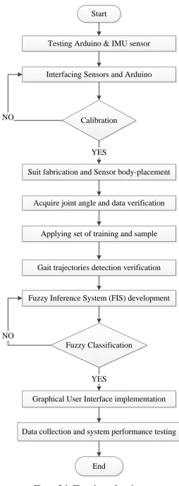
A workflow to achieve the aim was illustrated in Figure 3.1. This flow chart will guide the step of process to implement hardware and software in designing this prototype. A detail process was listed in table of Gantt chart.
Start
Testing Arduino & IMU sensor
Interfacing Sensors and Arduino
Graphical User Interface implementation
End Calibration NO
YES
Acquire joint angle and data verification
Data collection and system performance testing Gait trajectories detection verification Suit fabrication and Sensor body-placement
Applying set of training and sample
Fuzzy Classification
Fuzzy Inference System (FIS) development
NO
[image:25.595.198.453.65.754.2]YES
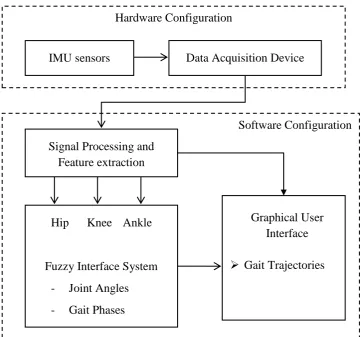
regarding to point of interest (body segment), then the data is send to data acquisition device specifically Arduino microcontroller via serial communication. At the same time, USB connection cable provides a power source to microcontroller and sensors. In personal computer, GUI MATLAB program receives the data from a serial port to process the signal and perform some extraction thus provides visual representation of the data in graphical form. Analysing Fuzzy tools in GUI will differentiate the angular displacement of lower body segment through defined rules thus represent a desired pattern. As a result, the system provides continuous and temporal data to be investigated as a feedback view by therapist to determine the evaluation rehabilitation or maintenance process.
[image:26.595.143.505.388.725.2]Hardware is explained with initial theory behind the sensors, the figures of used components and the assembly of the whole system. In a final section, software is introduced with explanations of both the microcontroller and the MATLAB code.
Figure 3.2: A complete system architecture.
Software Configuration Hardware Configuration
Data Acquisition Device IMU sensors
Signal Processing and Feature extraction
Hip Knee Ankle
Fuzzy Interface System
- Joint Angles - Gait Phases
Graphical User Interface
3.3 Hardware Implementation
3.3.1 Power Supply
USB connection cable provides a power source from computer USB port to microcontroller and sensors. While the Arduino microcontroller has a DC power jack to allow for connection with an external DC sources, thus supplies power to the board as well as all the ports and pins connected to it. The use of external battery to supply enough power for an entire workout will be discuss later if it necessary. By calculating the current draw of each IMU as well as the Arduino, it was determined that provide enough current to satisfy the necessary requirements.
3.3.2 Arduino Microcontroller
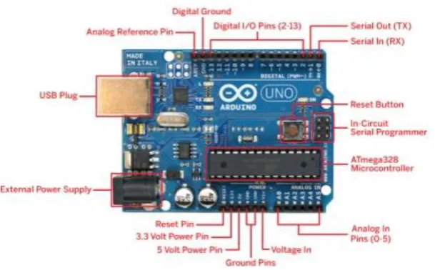
[image:27.595.170.475.468.657.2]A central processing unit for the prototype is Arduino Microcontroller. The Arduino requires a USB connection to a PC in order to receive any software programming to run the Arduino. The Arduino can functions by providing a power sources through a battery or via USB port connection.
Figure 3.3: Arduino Uno Microcontroller
of power port for 5V and 3.3V supply to all the sensors and offers 14 input/output digital pins of which 6 of them are PWM featured. The Arduino also allows for connections with attachments called shields, which can serve purposes such as SD card, wireless, and protoboard capabilities.
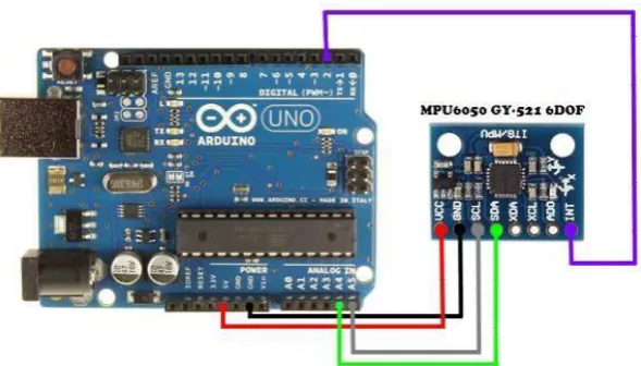
3.3.3 IMU sensor (MPU 6050)
The selection of MPU6050 as main sensing unit due to chip on-board Inertial Measurement Unit (IMU) sensor contains 3-axis gyroscope and 3-axis accelerometer. The accelerometer gives data based on the acceleration felt by the IMU in x, y, and z directions, the gyroscope gives measurements based on the angular acceleration around each of these axes.MPU6050 is a low cost 6 DOF IMU has features include a built in 16-bit analog to digital conversion and a proprietary Digital Motion Processor (DMP) unit.
[image:28.595.172.467.546.714.2]The DMP combines the raw data and performs some complex calculations on-board to minimize the errors while it produces more accurate and robust output. The biggest advantage of the DMP is that it eliminate the need to perform complex calculation on Microprocessor side due to DMP has a built in auto-calibration function where the output of MPU6050 can be converted to Euler angles for user understand and read. The MPU6050 communicates with Arduino through an I2C-bus interface
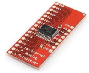
MPU6050 board has own voltage regulator on board but preferred to apply 5V to the VCC pin of the sensor board for good working on I2C communication. At the same time, the board has pull-up resistors on the I2C-bus. Both raw data from gyroscope and accelerometer are processing and feed to Arduino through I2C bus communication via pin SDA and SCL such illustrated as Figure 3.5. The pin AD0 selects between I2C address 0x68 and 0x69. That makes it possible to have two of these sensors in a project. Most breakout boards have a pull-up or pull-down resistor to make AD0 default low or high. Connect AD0 to GND or 3.3V for the other I2C address. When more MPU-6050 sensors are needed in a project, the I2C-bus can be extended with multiplexers.
Figure 3.5: CD74HC4067 Multiplexer
In order to connect multiple sensors on the bodysuit, it is necessary to separate the data lines for each IMU sensor because the data line of the Arduino microcontroller is only one pin on the board. The multiplexer works by connecting pins on the Arduino to the multiplexer, which allows for the Arduino to be programmed to select which sensor to communicate with. The bits that select which sensor to connect to are called the selector bits.
3.4 Software Implementation
3.4.1 Arduino
Arduino platform consists of essential parts that each of them performs a particular duty. Combination of these parts allows reading the data from sensors and eventually inputting them on the serial monitor for further processing in MATLAB which will be investigated in the next section.
#include <Wire.h>
#include “Kalman.h”
In the beginning of the code using Sketch in Arduino language, corresponding libraries need named “Wire” to active the I2C communication with the sensor board and while ‘Kalman’ for applying the Kalman filter on calculated angle at the output data since the gyroscope easy produce a drift if rapid changing on orientation. Arduino support several baud rates, the speed of transferring data, where the higher allows more data to be transmitted in unit of time.
void setup() {
Serial.begin(115200);
Wire.begin( );
The final part of the code includes sending the data on a serial monitor for observation and then the data can be used for MATLAB program.
Serial.print(kalAngleX); Serial.print(":");
Serial.print(kalAngleY);
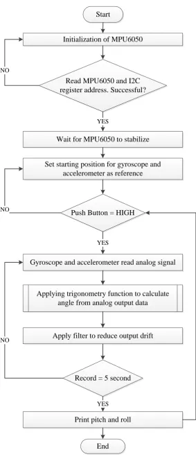
Start
Initialization of MPU6050
Apply filter to reduce output drift
End
Read MPU6050 and I2C register address. Successful?
Wait for MPU6050 to stabilize YES
Set starting position for gyroscope and accelerometer as reference
Gyroscope and accelerometer read analog signal Push Button = HIGH
YES
Applying trigonometry function to calculate angle from analog output data NO
Record = 5 second NO
[image:31.595.181.465.63.727.2]Print pitch and roll YES NO
The MATLAB program is written for the purpose of obtaining the data from the serial port that the Arduino microprocessor sends to post-processor thus plotting a graphical gait pattern. Essential parts of the MATLAB program includes setting communication and configuration, adjusting sample rate, reading and separating sensor data from each other, preparing the graphs and finally plotting the data. The FIS was initially developed utilizing the fuzzy logic toolbox available in MATLAB. A graphical user interface (GUI) developed for instantaneous data acquisition, graphical representation in degree of angle for the thigh angular displacement, shank angular displacement and foot angular displacement and the gait pattern detection.
s = serial ('COM7');
set (s, 'BaudRate', 115200);
fopen (s);
str = fscanf(s);
At first the communication with the computer port is established making the data transfer feasible by let Arduino to send the sensor data to a laptop via communication port specified so it is chosen as the same for obtaining the data and processing in MATLAB. The baud rate is specified as 115200 for same speed declaration in the Arduino code. The serial port is opened for necessary to start the program with these lines for performing initializations.
index1 = find(str == ':');
str1 = str(1:index1-1);
Kx(i) = str2double(str1);
3.4.3 Fuzzy Logic Toolbox
Fuzzy logic defines an output with a degree of membership in contrast to crisp logic which forces to draw a sharp boundary between members and non-members of a class. Crisp logic defines ‘0’ if the input is a non-member and ‘1’ if the input is a
member. Fuzzy logic defines a value between ‘0’ and ‘1’ depending on the degree to which the input belongs to the member [23].
Fuzzy logic is heuristic method to distinguish gait phases with respect to variations of gait parameters from one gait phase to another. The concept of fuzzy logic could applied to implement a gait phase detection algorithm by determine a membership function (MF) that belongs to desired variable of gait parameters. The FIS was designed such that each gait phase will have a membership value of ‘1’ to indicate that the gait phase was fully detected and a membership value of ‘0’ to indicate the gait phase is not detected.
Fuzzy controller system consists of three inputs as defined as hip joint, knee joint and ankle joint. The variability of the joint angles can be used to identify the output part of FIS, a gait phases detected at a time instance. The range of values of hip, knee and ankle joint angles were divided in to several Membership Functions (MFs). The MFs were defined as triangular membership functions for all input variables then FIS applying the defined rule set to map the inputs to the output where defuzzified to obtain crisp output. MATLAB was used in developing a system which facilitates post processing of data acquisition, performing graphical interface for gait detection. End of process, fuzzy control system required to detect gait phase in smooth and continuous detection using data acquired.
3.5 Sensor Placements and Experimental Setup
guard socks.
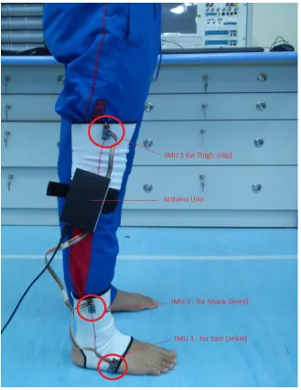
Figure 3.7: The placement of IMU sensors on the lower part of body segment.
Figure 3.8: A pathway lane for recording walking gait.
In order to acquire same length of the gait data, a walking lane was setup such illustrated in Figure 3. 8. It designed to set the walk performed by subjects are strict to at least three gait cycles so that the sensor was command and could acquire the gait data for 5 seconds. During stand, subjects were asked to wear the bodysuit and the sensor alignment was adjusted to make sure gait recording acquires a data aligned in respective axis setting. After the subject confirming the comfort of bodysuit, they will perform several normal gait of walking.
3.6 Angle Measurement using Wearable Sensors
REFERENCES
1. V. Karriem, Norwood, (2014). Limb Amputation: Reasons, Procedure, Recovery. Retrieved on May 26, 2014 from
http://www.webmd.com/a-to-z-guides/definition-amputation
2. E. Strait, Prosthetics in Developing Countries, pp.3-5, 2006.
3. C. Nielsen, R. A. Psonak, T. L. Kalter, "Factors Affecting the Use of Prosthetic Services", Journal of Prosthetics and Orthotics, Volume 1, Number 4, pp.242-249.
4. H. B. Skinner, D. J. Effeney, "Gait Analysis in Amputees", American Journal of Physical Medicine, vol. 64, pp.82-89, 1985.
5. A. Esquenazi, "Gait analysis in lower-limb amputation and prosthetic rehabilitation", Phys. Med. Rehabil. Clin. N. Am., vol. 25, no. 1, pp.153–67, Feb. 2014.
6. M. Saleh, G. Murdoch, "Obervation and Measurement in Gait Assessment", The Journal of Bone and Joint Surgery, vol. 67, no. 2, 1985.
7. J. S. Rietman, K. Postema, and J. H. B. Geertzen, “Gait analysis in prosthetics: opinions, ideas and conclusions.,” Prosthetic. Orthotic. International., vol. 26,
no. 1, pp. 50–7, Apr. 2002.
8. N. Pinkam, I. Nilkhamhang, “Optimization of Networked Smart Shoe for Gait Analysis using Heuristic Algorithms with Automated Thresholding”,
Kasetsart J. (National Science) 47 : 909-924, 2013.
9. C. Senanayake, S. M. N. A. Senanayake, "Human Assisted Tools for Gait Analysis and Intelligent Gait Phase Detection", Conference on Innovative Technologies in Intelligent Systems and Industrial Applications, Monash
University, Malaysia, pp. 230–235, 2009.
11. W. Tao, T. Liu, R. Zheng, and H. Feng, "Gait analysis using wearable sensors", Sensors (Basel)., vol. 12, no. 2, pp. 2255–83, Jan. 2012.
12. R. Seymour, Prosthetics and Orthotics: Lower Limb and Spinal. Lippincott Williams & Wilkins, 2002, p. 485.
13. M. Pushparani, B. Kalaivani, "Identification of Gait Disorders Using Fuzzy Expert System", International Journal of Science and Research, Vol. 3 Issue 10, pp.868-872, 2014.
14. N. Berger, “Analysis of Amputee Gait,” pp. 1–13, 2014.
15. B. S. Patrick, “Clinical Observation of Gait Analysis,” vol. 64, no. 3, p. E577, Mar. 2009.
16. S. J. Hillman, S. C. Donald, J. Herman, E. McCurrach, A. McGarry, A. M. Richardson, and J. E. Robb, “Repeatability of A New Observational Gait
Score For Unilateral Lower Limb Amputees.,” Gait Posture, vol. 32, no. 1, pp. 39–45, May 2010.
17. J. Bae, K. Kong, N. Byl, and M. Tomizuka, “A Mobile Gait Monitoring System For Gait Analysis,” 2009 IEEE Int. Conf. Rehabil. Robot., pp. 73–79, Jun. 2009.
18. R. Lemoyne, T. Mastroianni, and W. Grundfest, “Wireless Accelerometer iPod Application for Quantifying Gait Characteristics,” Engineering in Medicine and Biology Society, EMBC, 2011 Annual International Conference
of the IEEE, DOI:10.1109/IEMBS.2011.6091949, pp. 7904–7907, 2011.
19. J. Pawin, T. Khaorapapong, and S. Chawalit, “Neural-based human’s abnormal gait detection using Force Sensitive Resistors,” Fourth Int. Work.
Adv. Comput. Intell., pp. 224–229, Oct. 2011.
20. A. Mai, S. Member, and S. Commuri, “Gait identification for an intelligent prosthetic foot,” pp. 1341–1346, 2011.
21. Y. Hayashi, N. Tsujiuchi, T. Koizumi, and Y. Makino, “Biomechanical Kinetic Consideration of the Unrestrained Trans-Femoral Prosthetic Gait Using Energy Consumption,” pp. 2278–2283, 2013.
22. T. Seel, J. Raisch, and T. Schauer, “IMU-Based Joint Angle Measurement for Gait Analysis,” Sensors, DOI:10.3390/s140406891, pp. 6891–6909, 2014.
Recognit., pp. 586–591, 2009
24. Omer (2014), Arduino with MPU6050 and Angle Calculation, retrieved on December 30, 2014 from http://hobbylogs.me.pn/?p=47
25. O. A. Enriquez, M. I. C. Murguia, R. S. Roriguez, "Kinematic Analysis of Gait Cycle Using a Fuzzy System for Medical Diagnosis", Fuzzy Information Processing Society (NAFIPS), 2012 Annual Meeting of the North American,
![Table 2.1: Summary of motion positions on hip joint, knee joint and ankle joint[12].](https://thumb-us.123doks.com/thumbv2/123dok_us/8762175.894529/18.595.105.533.358.554/table-summary-motion-positions-joint-joint-ankle-joint.webp)
![Figure 2.2: A measurement of angular displacements of the lower extremity [11].](https://thumb-us.123doks.com/thumbv2/123dok_us/8762175.894529/19.595.118.522.76.364/figure-measurement-angular-displacements-lower-extremity.webp)