International Journal of Emerging Technology and Advanced Engineering
Website: www.ijetae.com (ISSN 2250-2459,Volume 1, Issue 1, November 2011)10
A New software Test Model “Graph Model”
Abdulla Shaik
Department of MCA, RTMNU, Nuva College of Engineering & Technology,
Nagpur. Maharashtra 440015, India
Abstract— Organizations that are developing custom software solution are faced with the difficult choice of picking the right software development life cycle (SDLC). Defining or selecting an SDLC should be undertaken as a project with full time resources that have the appropriate level of expertise. It is an extremely high leverage effort. It also represents a major cultural change for the staff. It must be planned and executed in as professional a manner as possible.
Here we are giving one model which will help in software development in an effective manner. Mostly a SDLC has three primary objectives: ensure that high quality systems are delivered, provide strong management controls over the projects, and maximize the productivity of the system. In order to meet these objectives our SDLC is having same approach like traditional waterfall model. It is being able to support projects and systems of various scopes and types, supporting all of the technical activities, supporting all of the management activities, being highly usable, and it providing guidance on how to it will work.
The major advantage of this SDLC is that in the middle if any changes are require it can be process easily.
Key Words: Design, High-Level, Implementation Integration, Low-Level, Performance, Requirements
I. INTRODUCTION
In order to meet all of the SDLC's objectives and requirements there are certain design approaches that are required. In this the design of the system is classified in two parts low-level and high-level to meet the objective of the life cycle. These designs are implemented separately to improve the code efficiency. And the test of the system is done in two ways which is in low level and integration level finally the environment and system performers is check. After all it sends to maintenance phase.
The main aim or objective of this mode to give idea about a new kind of model in systems development lifecycle (SDLC) is and working style of this model as well as advantage and disadvantages. Next and note least how if will differ with other models and the similarities with other models.
II. SELECTION OF SDLC
A software development life cycle (SDLC) is a software development process, is a methodology an organization developing custom software must use to be successful. Industry experience demonstrates that attempting to engage in the production of software without a well defined, well communicated and relevant SDLC is a recipe for disaster. The industry has defined dozens of possible SDLCs. The SDLC are all defined by process models and tools that must be used to implement the methodology.
Selecting an SDLC is not easy:
Selecting the right SDLC is a process in itself that organization can implement internally or consult for.
There are dozens of available SDLCs, more or less mainstream. It is therefore difficult for organization to filter out the SDLCs that may be relevant to their organizations from the ones that would be terribly wrong.
There is no best SDLC. SDLC have been designed to meet the needs of certain situations, certain verticals, certain type of software, certain type of organizations.
There is no one-size-fit all SDLC.
Some SDLCs are marketed as products and services. Is SDLCs are process, creates and maintains to all
systems?
Is the SDLC appropriate for the size of our team? Is the SDLC appropriate for the geographical
situation?
Is the SDLC appropriate for the size and complexity of our software?
Is the SDLC appropriate for the type of projects we do?
Is the SDLC in line with our business strategy? Is the SDLC appropriate for our Industry?
International Journal of Emerging Technology and Advanced Engineering
Website: www.ijetae.com (ISSN 2250-2459,Volume 1, Issue 1, November 2011)11 These are some questions witch lead to develop the new SDLC. This SDLC is also unable to answer all the quotations and it is also not able to meet all the requirements. But hope it will give better idea than other SDLCs.
Example for selecting solution for problem is shown in below fig:
Fig: 2.1. Typical methodology to develop system Souce: Software Development Life Cycle (SDLC)
Here in this user can select any one like the same way SDLCs are not equal in their properties, advantages and disadvantages. In order to select the right SDLC one must be very familiar and experienced with the candidate SDLC that will be evaluated. In particular, one must not only trust the promises of the marketing brochure that will promote the SDLC. Achieving such knowledge is not straightforward and it is recommended to seek advisory services.
The industry has defined multiple SDLCs known as Waterfall, V-model, RAD, RUP, Spiral, FDD, DSDM, Scrum, to name a few with very different applicability.
Fig: 2.2. Traditional and Simplified view of software
To assess the SDLC, one must truly understand the nature of organization. Software would have completely different requirements in term of software quality, time-to-market or economics. One must study the business context, industry requirements and business strategy to be able to value the candidate SDLC against their selection criteria and SDLC qualitatively.
III. OBJECTIVES OF THIS SDLC
The SDLC is itself a system. When we plan to develop, acquire or revise a system we must be absolutely clear on the objectives of that system. The objectives must be stated in terms of the expected benefits that the business expects from investing in that system. The objectives define the expected return on investment.
Like other SDLCs this also has some primary business objectives:
a) Ensure the delivery of high quality systems; b) Provide strong management controls; c) Maximize productivity.
d) Reduce the Errors.
This SDLC is also ensuring that it can produce more function, with higher quality, in less time, with fewer resources and in a predictable manner.
IV. THE GRAPH SDLC MODEL
International Journal of Emerging Technology and Advanced Engineering
Website: www.ijetae.com (ISSN 2250-2459,Volume 1, Issue 1, November 2011)12
Fig: 4.1. The Graph SDLC Model
4.1 Requirements Gathering
One of the most difficult phases of the project is gathering requirements from stakeholders. Under the best circumstances requirements are often vague, because it is difficult for customers to articulate their needs before they see the end product. In addition, some customers have personal agendas, which make identifying the true needs difficult.
With the requirements gathering phase this model is begin the life cycle just like waterfall model. Before development is started, the entire system requirements plan is created. This plan focused on meeting the functional and business specified requirements. The requirements gathering process takes as its input the goals identified in the high-level requirements section of the project plan. Each goal will be refined into a set of one or more requirements. These requirements define the major functions of the application.
Fig: 4.1(a). Base for requirement gathering
The fig 4.1a is help to understand why requirements gathering are particularly important is when stakeholder
business requirement is a description of the features and functions of a product that satisfies a want or need enabling people to do, know, operate, or have something new or in a new way. This description usually is in the form of text, but could be documented in a graphical model called Requirements Document and the Requirements Traceability Matrix (RTM). The requirements document contains complete descriptions of each requirement, including diagrams and references to external documents as necessary.
The RTM shows that each requirement developed during this stage is formally linked to a specific product goal. In this format, each requirement can be traced to a specific product goal, hence the term requirements traceability. The outputs of the requirements definition stage include the requirements document, the RTM, and an updated project plan.
Finally when the business customers and project team have a relationship built on trust, they can more quickly work together to produce a product of value to the organization.
4.2 Low Level Design
The design stage takes as its initial input the requirements identified in the approved requirements document. Design elements generally include functional hierarchy diagrams, screen layout diagrams, tables of business rules, business process diagrams, pseudo code, and a complete entity-relationship diagram with a full data dictionary.
These design elements are intended to describe the software in sufficient detail that skilled programmers may develop the software with minimal additional input. When the design document is finalized and accepted, the outputs of the design stage are the design document is plan.
International Journal of Emerging Technology and Advanced Engineering
Website: www.ijetae.com (ISSN 2250-2459,Volume 1, Issue 1, November 2011)13
Fig: 4.2 Example for Low level model
Fig: 4.2 is showing that how the work is distributed in modules. After dividing into modules each and every module is going to be solve and finally the entire work is going to be integrated for next level of development.
4.3 High Level Design
Delivering of the project into modules or interfaces is known as high level design. All The Data base Related Designs and Connection designs related to one to other module or interface are design by high qualified people in the organization in this phase. In this usually the team leaders or project manager do this job. Like Pseudo code generation, collaboration diagrams, component and deployment diagrams and other in the design document.
Fig: 4.3 Example for High level model
4.4 Implementation
Commonly this phase is initiated after the system has been tested and accepted by the user. Activities in this phase include notification of implementation to end users, execution of the previously defined training plan, data entry or code conversion, completion of security certification and accreditation and post implementation evaluation. This phase continues until the system is operating in production in accordance with the defined user requirements.
The new system can fall into three categories, replacement of a manual process, replacement of a legacy system, or upgrade to an existing system. Regardless of the type of system, all aspects of the implementation phase should be followed. This will ensure the smoothest possible transition to the organization‟s desired goal.
In this Graph SDLC each person involved having their own responsibilities to implement the design to full fill the user requirements.
Project Manager: The project leader is responsible and accountable for the successful execution of the Implementation Phase. The project leader is responsible for leading the team that accomplishes the tasks in the SDLC design and customer requiems.
Team Lead: The team Lead is responsible for
accomplishing assigned tasks and implementation of high level design according to the documentation as directed by the Project Manager.
Developer: The project team members/developers are
responsible for accomplishing assigned tasks and implementation of low level design according to the documentation as directed by the Project Manager/Team Lead.
Procurement Officer: The Procurement Officer is
responsible and accountable for preparing solicitation documents under the guidance of the project manager in each and every phase of the SDLC.
International Journal of Emerging Technology and Advanced Engineering
Website: www.ijetae.com (ISSN 2250-2459,Volume 1, Issue 1, November 2011)14 4.5 Unit Testing
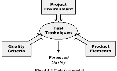
[image:5.612.70.275.223.348.2]Software testing is the process used to assess the quality of the computer software. This is an empirical technical investigation conducted to provide quality of the product and finding the bugs in software product. The general test criteria is given bellow
Fig: 4.5.1 Unit test model
This Graph SDLC is providing the dynamic test methodology to test the software. This describes the Dynamic behavior of the code.
Units are the smallest building blocks of software. The term unit testing refers to the individual testing of separate units of a software system. In object-oriented systems, these units typically are classes and methods. Unit testing is the process of validating such small building blocks of a complex system much before testing an integrated large module or the system as a whole. Some of the major benefits are:
• Be able to test parts of a project with out waiting for the other parts to be available,
• Achieve parallelism in testing by being able to test and fix problems simultaneously by many engineers,
• Be able to detect and remove defects at a much less cost compared to other later stages of testing,
• Be able to take advantage of a number of formal testing techniques available for unit testing,
• Simplify debugging by limiting to a small unit the possible code areas in which to search for bugs,
• Be able to test internal conditions that are not easily reached by external inputs in the larger integrated systems • Be able to achieve a high level of structural coverage of the code
• Avoid lengthy compile-build-debug cycles when debugging difficult problems.
By busing Unit Testing in This Graph Model We can achieve all the properties of the unit test. A number of effective testing techniques are usable in unit testing stage. The testing techniques may be broadly divided into three types:
• Functional Testing • Structural Testing
• Heuristic or Intuitive Testing
[image:5.612.316.546.303.408.2]The defects in software can in general be classified as Omissions, Surprises and Wrong Implementations. Omissions are requirements that are missed in the implementation, Surprises are implementations that are not found in the requirements and wrong implementation is incorrect implementation of a requirement.
Fig 4.5.2 Testing techniques and types of defects Source: White paper on Unit Testing
But Intuitive testing is effective only when complementing the systematic types of Functional and Structural testing techniques.
Functional testing Techniques:
Boundary Value Analysis: Testing the edge conditions of boundaries
Equivalence Partitioning: Grouping test cases into classes in which executing one test cases is equivalent to executing any other test cases in the same group
Cause Effect Graphing: When the behavior of the unit under test is specified as cause and effect. Design test cases that validate this relationship.
Structural test Cases Techniques:
Statement Coverage: Identify Test cases such that every line of code is executed in one test case or other.
International Journal of Emerging Technology and Advanced Engineering
Website: www.ijetae.com (ISSN 2250-2459,Volume 1, Issue 1, November 2011)15
Condition Coverage: Identify Test cases such that
condition in each predicate expression is evaluated in all possible ways.
Modified Condition-Decision Coverage: Identify Test
[image:6.612.56.293.221.402.2]cases such that each Boolean operand can independently affect the outcome of a decision.
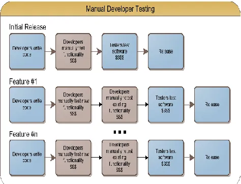
Fig 4.5.3 Simple Model for Manual Testing
Fig 4.5.4 Simple Model for Automated Testing
4.6 Integration Testing
This is the phase of the software testing in which individual software modules are combined and tested as a group. It follows unit testing and proceeds the system testing. It takes as its input modules that have been unit tested, groups them in larger aggregates, applies test defined in an integration test plan to those aggregates, and delivers as its output the integrated system ready for system testing. Once the modules are developed then this phase is going to start. In this developers will link the modules in different approaches with the help of interfaces while linking developers will test the interfaces.
There are four types of integration testing approaches. Any one (or a mixture) of the following approaches can be used to develop the integration test plan. Those approaches are the following:
• Big bang approach • Top-down approach • Bottom-up approach • Mixed-approach
4.6.1 Big-Bang Integration Testing
[image:6.612.58.293.436.635.2]It is the simplest integration testing approach, where all the modules making up a system are integrated in a single step. In simple words, all the modules of the system tested at a time. However, this technique is practicable only for very small systems. The main problem with this approach is that once an error is found during the integration testing, it is very difficult to localize the error as the error may potentially belong to any of the modules being integrated. Therefore, debugging errors reported during big bang integration testing are very expensive to fix.
International Journal of Emerging Technology and Advanced Engineering
Website: www.ijetae.com (ISSN 2250-2459,Volume 1, Issue 1, November 2011)16 4.6.2 Bottom-Up Integration Testing
In bottom-up testing, each subsystem is tested separately and then the full system is tested. A subsystem might consist of many modules which communicate among each other through well-defined interfaces. The primary purpose of testing each subsystem is to test the interfaces among various modules making up the subsystem. Both control and data interfaces are tested. The test cases must be carefully chosen to exercise the interfaces in all possible manners.
Large software systems normally require several levels of subsystem testing; lower-level subsystems are successively combined to form higher-level subsystems. A principal advantage of bottom-up integration testing is that several disjoint subsystems can be tested simultaneously. In a pure bottom-up testing no stubs are required, only test-drivers are required. A disadvantage of bottom-up testing is the complexity that occurs when the system is made up of a large number of small subsystems. The extreme case corresponds to the big-bang approach.
4.6.3 Top-Down Integration Testing
Top-down integration testing starts with main routine and one or more sub routines in the system. After the top-level „skeleton‟ has been tested, the immediately subroutines of the „skeleton‟ are combined with it and tested. Top-down integration testing approach requires the use of program stubs to simulate the effect of lower-level routines that are called by the routines under test. Pure top-down integration does not require any driver routines. A disadvantage of the top-down integration testing approach is that in the absence of lower-level routines, many times it may become difficult to exercise the top level routines in the desired manner since the lower-level routines perform several low-level functions such as I/O.
4.6.4 Mixed Integration Testing
A mixed (also called sandwiched) integration testing follows a combination of top-down and bottom-up testing approaches. The technique for writing a program using top–down methods is to write a main procedure that names all the major functions it will need. Later, the programming team looks at the requirements of each of those functions and the process is repeated. These compartmentalized sub-routines eventually will perform actions so simple they can
be easily and concisely coded. When all the various sub-routines have been coded the program is ready for testing.
In top-down approach, testing can start only after the top-level modules have been coded and unit tested. Similarly, bottom-up testing can start only after the bottom level modules are ready. In a bottom–up approach, the individual base elements of the system are first specified in great detail. These elements are then linked together to form larger subsystems, which then in turn are linked, sometimes in many levels, until a complete top-level system is formed. This strategy often resembles a "seed" model, whereby the beginnings are small, but eventually grow in complexity and completeness.
The mixed approach overcomes this shortcoming of the top-down and bottom-up approaches. In the mixed testing approaches, testing can start as and when modules become available. Therefore, this is one of the most commonly used integration testing approaches.
Fig: 4.6.4 Different software testing approaches
4.7 System Testing
International Journal of Emerging Technology and Advanced Engineering
Website: www.ijetae.com (ISSN 2250-2459,Volume 1, Issue 1, November 2011)17 There are essentially three main kinds of system testing:
• Alpha Testing. Alpha testing refers to the system testing carried out by the test team within the developing organization. The software is used in a natural setting along with the developer. The developer records the errors and usages problems. This is done in controlled environment.
• Beta testing. Beta testing is the system testing performed by a select group of friendly customers. The Beta testing is conducted at one or more customer‟s site by the end users of the software. The developer is not present during these tests. The customer records the errors and reports these to the developers. This is followed by the release of the product.
• Acceptance Testing. Acceptance testing is the system testing performed by the customer to determine whether he should accept the delivery of the system. It generally involves running a suite of test on the completed system.
In each of the above types of tests, various kinds of test cases are designed by referring to the SRS document. Broadly, these tests can be classified into functionality and performance tests. The functionality tests test the functionality of the software to check whether it satisfies the functional requirements as documented in the SRS document. The performance tests test the conformance of the system with the nonfunctional requirements of the system.
4.8 Environment & Load Testing
4.8.1 Environment Testing
A Test Tnvironment is any development environment that is primarily used to perform incremental and iterative system testing on an evolving application. Before delivering the product/software to the customer the developed system is check in different environments. It helps to ensure that the system is fully operational, install the system in a production environment.
The Graph Model is providing this facility to the system before it release to the customer. The Environment is a combination of three different layers.
Presentation layer Business layer Database layer
And the developed software is test in
i. Standalone Environment ii. Client/Server Environment iii. Web Environment
iv. Distributed Environment
Fig:4.8.1(a). Different testing environments
International Journal of Emerging Technology and Advanced Engineering
Website: www.ijetae.com (ISSN 2250-2459,Volume 1, Issue 1, November 2011)18 4.8.2 Load Testing
Load testing is the process of subjecting a computer, peripheral, server, network or application to a work level approaching the limits of its specifications. Load testing can be done under controlled lab conditions to compare the capabilities of different systems or to accurately measure the capabilities of a single system. Load testing can also be done in the field to obtain a qualitative idea of how well a system functions in the "real world." Load testing is a part of a more general process known as performance testing.
When it finally appears that your application has been successfully integrated into the shared environment, it is time to turn up the user load to reflect production traffic. If your application holds up through this test and meets it‟s SLAs, then it give confidence that it was headed in the right direction. If it fails to meet its SLAs in this test, it need to enable deeper performance diagnostics, filter through the application service requests and identify new bottlenecks by using the links in Graph SDLC.
Minimize the risk of deploying systems that don't meet quality and performance requirements
Find the root cause of performance bottlenecks and system failures with ease
Optimize user experience by testing against service levels to ensure that Service Level Agreements are met in production
Reduce the costs of defects by testing remote components early in the development cycle
Minimize hardware and software costs by accurately predicting system capacity
Provides performance and capacity statistics Tests scalability of the site
Allows you to evaluate the bandwidth for the amount of data sent and received
Allows you to verify predicted performance under varying conditions
Verifies the tuning of your system through benchmarking
Fig: 4.8.2. Load testing clients direct volume into the server environment
The following tests will be run:
Capacity Test – Determines the maximum number of
concurrent users that the application server can support under a given configuration while maintaining an acceptable response time and error rate.
Consistent Load Test –Long-running stress test that drives a continuous load on the application server for an extended period of time. The main purpose of this type of test is to ensure the application can sustain acceptable levels of performance over an extended period of time without exhibiting degradation, such as might be caused by a memory leak.
Single Function Stress Test – A test where 100 users perform the same function with no wait times and no ramp up time. This test will help determine how the application reacts to periods of extreme test in a very narrow area of the code.
International Journal of Emerging Technology and Advanced Engineering
Website: www.ijetae.com (ISSN 2250-2459,Volume 1, Issue 1, November 2011)19 4.9 Maintenance
Software will definitely undergo change once it is delivered to the customer. There are many reasons for the change. Change could happen because of some unexpected input values into the system. In addition, the changes in the system could directly affect the software operations. The software should be developed to accommodate changes that could happen during the post implementation period.
At this phase of the SDLC all security activities have been at least initiated or completed. An update must be made to the System Security plan; an update and test of the contingency plan should be completed. Continuous vigilance should be given to virus and intruder detection. The Project Manager must be sure that security operating procedures are kept updated accordingly.
V. CONCLUSION
The selection of an SDLC is critical and cannot be improvised or influenced by industry trends. A SDLC selection and adoption process is needed so that organizations maximize their chances to deliver their software successfully. Selecting and adopting the right SDLC is a management decision with long term implications. Thus this Graph SDLC is providing one of the best approaches to develop software without having any defects and interaction with each other phase in the model. The final and major goal of this model is to achieve error free/defect free software as outcome.
Acknowledgement
I am grateful to My Brothers Dr. Abdul Rahaman and Dr. Nazer Shaik , Dr. Ajay Shenkar Sing and P. Manoj Kumar for giving guideline to me. Finally last but not the least Mr. A. Hasheem Babu, Mr. Murali Mohan and other my friends for their insightful comments.
References
[1] Andrews, D. M., and Benson, J. P. An automated program testing method and its implementation. Fifth International Conference on Software Engineering, San Diego, Calif., March 9-12, 1981. [2] Abe, J., Sakamura, K., and Aiso, H. An analysis of software project
failures. Fourth International Conference on Software Engineering, Munich, Germany, September 17-19, 1979.
[3] Baker, A. L. A comparison of measures of control flow complexity.
IEEE Transactions on Software Engineering6:506-511 (1980).
[4] ANSI/IEEE Standard 729-1983. Glossary of Software Engineering Terminology
[5] ANSI/IEEE Standard 830-1984. Software Requirements Specifications.
[6] ANSI/IEEE Standard 1002-1987. Taxonomy for Software Engineering Standards.
[7] ANSI/IEEE Standard 730-1984. Software Quality Assurance Plans.
[8] Systems Development Lifecycle: Objectives and Requirements, 2003, Bender RBT Inc.
[9] Sorensen, Reed, “A Comparison of Software Development Methodologies,” Crosstalk, January 1995
[10] Guidelines for the Successful Acquisition and Management of Software Intensive Systems (GSAM), Version 3, Chapter 5, USAF Software Technology Support Center, May 2000.
[11] McKenzie, Charlotte A., MIS327 - Systems Analysis and Design, Course Schedule, 1999.
[12] An Overview Of Load Test Tools, Buret Julien, Droze Nicolas, 2003
About Author